WILKINS ZW209 Manual

1
a company
®
®
NOTE: Flushing of all pipe lines is to be performed to remove
all debris prior to installing valve.
NOTE: If installation is subject to very low ow or potentially
static conditions it is recommended a pressure relief valve
(1/2" minimum) be installed downstream of the pressure
reducing valve for additional system protection.
1. For making adjustments and servicing allow for adequate space
around the valve before installing valve.
2. When installing a ZW209 or ZW209BP, gate valves installed on
both inlet and outlet are recommended for maintenance allowing
for isolation of valve.
3.Position the valve in line matching the direction of ow as
indicatedonthevalvemodeltagwiththeproperdirectionofow
in the system. Once attached to line, double check all fasteners/
bolts in the pilot system and on main valve are tight and there is
no damage prior to pressurizing system.
NOTE: Pressure in some applications can be very high so be
thorough in checking and inspecting for proper installation
and makeup.
4. Zurn Wilkins valves are designed to operate in both the vertical
and horizontal positions. However, it is recommended that ZW209
6” and larger, be installation in the horizontal position. The hori-
zontal positioning of the larger valves avoids premature wear due
to the mass of plunger assemblies as well as allows for greater
accessibility during annual inspections, and maintenance.
ZW209 SCHEMATIC
STANDARD COMPONENTS
1 Main Valve
2 850MXL Isolation Valve
3 SXL Wye Type Strainer
4 Pressure Gauge
5 Restriction Tube Fitting
6 NR3XLHRSC PRV (15-150 psi)
Installation Troubleshooting Maintenance Instructions
Model ZW209 & ZW209BP
Pressure Reducing Valve Assembly & with Low Flow By-Pass
2", 2-1/2", 3", 4", 6" & 8"
OPTIONAL FEATURES
C 40XL Hydraulic Check w/
Isolation Valve
L SC1 Closing Speed Control
O SC1 Opening Speed Control
Z ZPI Valve Position Indicator
6 PV-PRD (20-200 psi)
the valve assembly it is also recommended that a ZPI valve
position indicator be installed to aid in verifying proper valve
movement.
3.Asthevalveisllingwithwater,itisnecessarytobleedthe
main valve and pilot system of air. To vent air, partially open or
loosenthehighestplugsorttingsinthesystem.TheZPIvalve
position indicator is a great location, as it has a test cock at the
top to vent air pressure. It may be necessary to bleed system
more than once. After removal of air in the system tighten all
loosettings.
4. Before setting valve, if valve is equipped with SC1 Flow con-
trols (O or L on ZW209 schematic) it is necessary to back out
the set screw a minimum of 3 turns from initial set point.
5. At this point with the upstream shutoff valve partially open,
slowly open the downstream shut off valve. Flow will begin to
occur and pressure should build up in valve and eventually
stabilize.
6.Nextitisadvisabletoowwaterthroughthevalvetoensureall
airhasbeenescapedfromsystem.Withwaterowingthrough
the valve the Zurn Wilkins PRV pilot can be set to the desired
pressure. To adjust the pilot, loosen jam nut on adjustment screw
and either turn adjustment screw in (to increase pressure) or
out (to decrease pressure). Tighten jam nut on pilot when the
desiredsettinghasbeenmade.ForZW209BPthelowowby-
pass control must be set 5 psi greater than main Pilot PRV.
7. To verify proper operation of ZW209 & ZW209BP close and
open downstream shut off valve several times to ensure down-
stream pressure is stable at set pressure. To verify by-pass op-
eration, close isolation valves on main pilot slowly. Then check
the downstream pressure. It should be regulating 5 psi higher
than normal Pilot PRV.
8. After pilot system has been adjusted and the valve is properly
regulating the main valve opening and closing speed controls
(O or L) can be adjusted as needed.
9. When setting speed controls, turning the adjustment screw
intothespeedcontrolwillrestricttheamountofowthroughthe
needle valve. Depending on whether the control is for opening
or closing (refer to ZW209 schematic) the control will either slow
the opening or closing of the main valve when the adjustment
screw is turned into the speed control. Adjust as needed and
tighten jam nut. In general a closing speed control on a ZW209
and ZW209BP should be at least 3 turns in from the furthest
open position to prevent high pressure surges downstream.
START-UP
CAUTION: To prevent personnel injury and damage to equip-
ment check that downstream venting is adequate prior to
start-up and test procedures. All adjustments under pressure
should be made slowly while under owing conditions. If
the main valve closes too fast it may cause surging in upstream
piping.
1. Open isolation valves (2) in the pilot system (see ZW209 or
ZW209BP schematic).
2. Then slowly open the upstream shutoff valve only enough to
llmainvalveassemblyandpilotsystem.Priortopressurizing
WILKINS, a ZURN company
1747 Commerce Way, Paso Robles, CA 93446 Phone:805-238-7100 Fax:805-238-5766
a company
®
®
Troubleshooting
The following troubleshooting information in Tables 1 & 2 deals
strictly with the ZW209 and ZW209BP valve and pilot systems.
It is recommended to verify that the pilot system is properly
functioning before troubleshooting the main valve. All trouble-
shooting can be performed without removing the cover. It is also
recommended to permanently install a model ZPI valve position
indicator and an additional gauge in one of the cover connec-
tions.
Installation / Start-up

PROBLEM POSSIBLE CAUSES CORRECTIVE ACTION
1. Main Valve fails to open 1. No pressure at valve Inlet 1. Check Inlet pressure
2. Main valve diaphragm assembly inoperative 2. Disassemble, clean, and polish stem, replace defective parts
3. Pilot Valve (Pilot PRV) not opening
1) No spring compression 1. Tighten adjusting screw.
2) Damaged spring 2. Disassemble and replace
2. Main Valve fails to close 1. Foreign matter between disc and seat or worn 1. Disassemble the main valve, remove debris, clean parts, and
disc replaced defective parts
2. Scale on stem or diaphragm ruptured 2. Clean parts, and replace defective parts
3. "Wye" Strainer plugged 3. Remove, clean, and/or replace
4. 38-850XL(ball valves) closed 4. Open ball valves
5. Pilot Valve (Pilot PRV) remains open:
1. Spring compressed solid 1. Back off adjusting screw
2. Mechanical obstruction 2. Disassemble and remove obstruction
3. Worn seal ring 3. Replace seal ring
3. Fails to Regulate 1. Air in main valve cover and/or tubing 1.Loosentopcoverplugandttingandbleedairoutofthesystem
DIAGNOSIS CHECKS
CAUTION: Do not service valve while under pressure. When
performing diagnosis checks on the ZW209 & ZW209BP
when the valve is fully open, high ow rates and high down-
stream pressures can occur. In order to prevent harm to
personnel, equipment, and downstream piping be sure that
there are no blocked valves in the system before performing
checks.
DIAPHRAGM CHECK
1. Slowly close upstream shut off valve and relieve all pres-
sure downstream.
Troubleshooting
2WILKINS, a ZURN company
1747 Commerce Way, Paso Robles, CA 93446 Phone:805-238-7100 Fax:805-238-5766
a company
®
®
PILOT SYSTEM FUNCTION CHECK
1. To verify if the Pilot PRV is properly regulating pressure,
rstslowlyclosetheoutletballvalvesinthepilotsystems.Then
allowthecovertollandthemainvalvetoclose.Ifinstalled,
verify the valve position indicator (model ZPI) is closed.
2. When the main valve is closed, close the cover ball valve to
keep the main valve closed.
3. Proceed with venting outlet downstream pressure by open-
ing a source downstream. When opening the downstream
sourceifthereiscontinuousow,themainvalveisnotsealing
properly. It is recommended that the main valve be disassem-
bled and inspected (Refer to “Disassembly” section).
4. When downstream pressure is relieved, proceed with slowly
closing the inlet isolation valve. It may be necessary to reopen
the outlet ball valve to relieve pressure on the downstream
gauge.
5. With the main valve closed and the system pressure re-
lieved slowly re-open the inlet isolation valve and re-pressurize
the pilot system leaving outlet isolation valve open and down-
streamsourceopentoallowow.Monitortheinletandoutlet
pressures and compare to the desired system settings. If the
outlet pressure is the same as the inlet or climbs more than 10
psiabovetheowingsetpoint,thePilotPRVisnotproperly
regulating (refer to the pilot troubleshooting Table 1. Corrective
Action section).
6. If the pressure is regulating to the desired system pressures
proceed with diagnosis checks for the main valve.
PROBLEM POSSIBLE CAUSES CORRECTIVE ACTION
1. Pilot Valve (Pilot PRV) not opening) 1. No spring compression 1. Tighten adjusting screw
2. Damaged spring 2. Disassemble and replace
3. Clogged "Wye" Strainer 3. (see plugged “Wye” strainer remedy)
4. Closed ball valve 4. Open ball valve
2. "Wye" Strainer plugged 1. Clogged with debris or mineral deposits 1. Disassemble and remove obstruction
3. Fails to Regulate 1. Air in main valve cover and/or tubing 1.Loosentopcoverplugandttingandbleedairoutofthesystem
2. Mechanical obstruction 2. Disassemble and remove obstruction, replace parts as necessary
3.Worndisc(regulating>10psiofowsetpoint) 3. Disassemble and replace disc
4. Pressure gauge fails to operate 1. Damage pressure gauge 1. Replace pressure gauge
2. Closed ball valve 2. Open ball valve
TABLE 2. MAIN VALVE TROUBLESHOOTING
When performing troubleshooting and diagnosis checks it is recommended that the following steps be performed in sequential order
for best results.
TABLE 1. PILOT SYSTEM TROUBLESHOOTING
2. With all pressure relieved in the main valve, close both inlet
and outlet isolation valves and remove side plug on cover and
leave off.
3. Then open upstream shut off valve partially, allowing water
toowthroughthevalve.Whileowingwatermonitortheopen-
ingonthecover.Ifuidbeginstoowoutoftheopenholein
the cover, then there is most likely damage to the diaphragm
oruidisleakingpastthediaphragmassemblyduetoloose
assembly. It is recommended that the valve cover be removed
to investigate the leakage (To remove cover see “Maintenance”
sectionforprocedures).Ifnowaterowsoutofcoverthenthe
diaphragm is good and you may proceed to the diaphragm
movement check.

WILKINS, a ZURN company
1747 Commerce Way, Paso Robles, CA 93446 Phone:805-238-7100 Fax:805-238-5766
a company
®
®
3
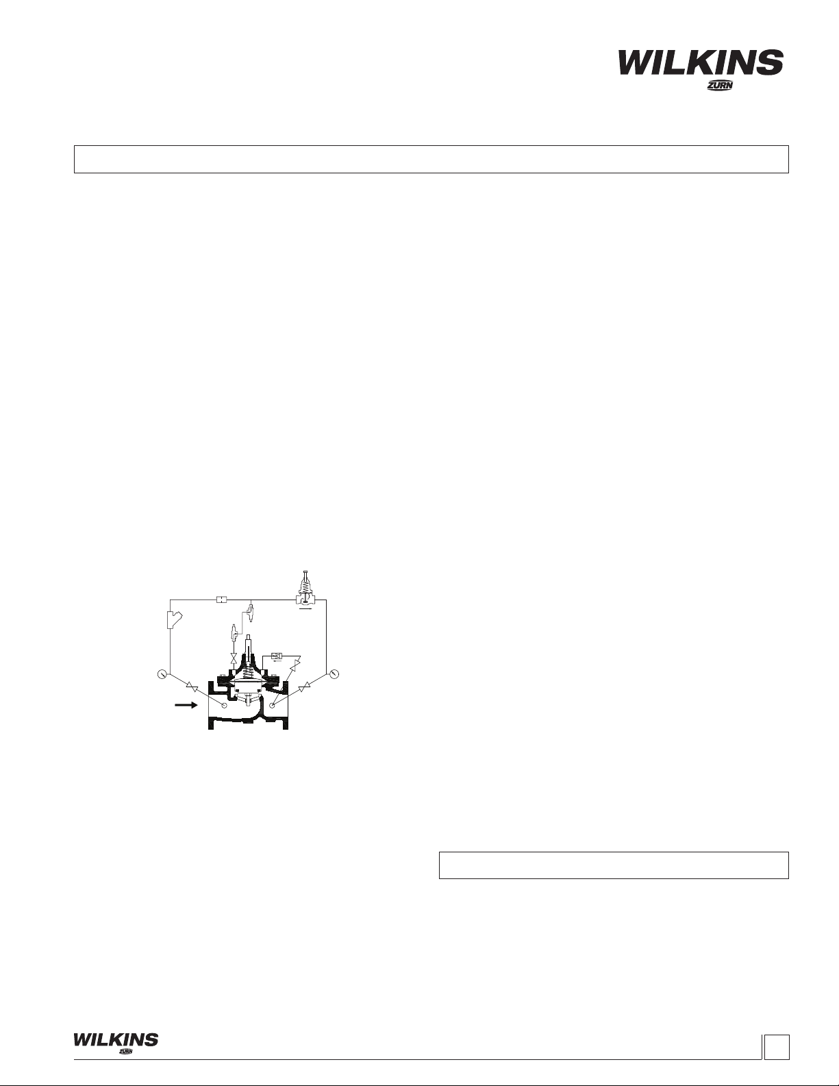
DIAPHRAGM MOVEMENT CHECK
1. The diaphragm movement check can be determined during
the diaphragm check or it can It can also be performed with the
use of a valve position indicator model ZPI.
2. Replace cover plug and open pilot ball valves on inlet and cover.
3.Closingtheoutletisolationballvalveswilldirecttheowto
the cover causing it to close. NOTE: Slow or delayed closing
of main valve is normal and is due to the time requirements
to ll, pressurize cover, and stretch the diaphragm into the
closed position. This normal delay is not mechanical bind-
ing of the valve assembly.
4. Using the valve position indicator, make note of the closed
position on the indicator. Compare distance of the open mark to
the close mark and compare to Table 3.
5. Verify that the main valve is closed, by opening a down-
stream source (not the outlet isolation ball valve on the main
body).Ifwatercontinuouslyows,thenthemainvalveisnot
sealing properly. Double check the valve movement matches
the values in Table 3 and refer to the disassembly procedures
section if it does not. This is an indication that the main valve
is not sealing due to an obstruction between the seat and
thesealoradamagedseal.Ifwaterdoesstopowingand
the measured valve movement does not match Table 3, then
there is possible damage under the cover. Remove cover to
identify obstruction and replace parts as necessary
TABLE 3. VALVE STEM TRAVEL
VALVE SIZE
(in)
VALVE SIZE
(mm)
STEM TRAVEL
(in)
STEM TRAVEL
(mm)
2" 50 0.7 18.0
2-1/2" 65 0.8 21.3
3" 80 0.9 23.4
4" 100 1.1 28.8
6" 150 1.7 43.4
8" 200 2.4 59.7
6. For smaller valves (6” and below) diaphragm checks can
be performed by hand with the use of a valve stem tool. The
valve stem tool can be made using Table 4 to create a “T” bar
handle with the appropriate threads on the opposite end of the
“T” handle.
TABLE 4. VALVE STEM THREAD SIZE
VALVE SIZE
(in)
THREAD SIZE
UNF INTERNAL
2" 10 - 32
2-1/2" 10 - 32
3" 1/4 - 20
4" 1/4 - 20
6" 3/8 - 20
8" 3/8 -16
7. To perform the diaphragm check using the vale stem tool,
rstremoveallpressureinthesystemandventthecover.
Then remove the center plug on the cover and insert tool into
the top of the stem threads. Once the tool is inserted, the
valve can be lifted up and the valve movement can be mea-
sured by creating marks on the tool in the opened and closed
positions. The distance between marks is the valve stem
travel. Replace or repair any parts as necessary.
SEAL CHECK
1. To check the seal of the valve disc, an additional pressure
gauge will be needed downstream of main valve.
2.Withthevalveowing,slowly,closepilotoutletballvalves
to apply pressure to cover and allow to close.
3. Open downstream source and monitor the pressure on the
inlet and installed outlet gauge, for one min. The pressure on
the outlet side should remain zero. If the pressure matches inlet
pressure or increases, the main valve is leaking or the outlet
ball valve on the pilot system is allowing pressure to creep by.
Either way it is recommended that the valve be disassembled
and inspected (refer to “Disassembly” section).
Maintenance Instructions
PREVENTATIVE MAINTENANCE
The Zurn Wilkins ZW200 models require minimal maintenance.
However, it is highly recommended to schedule annual inspec-
tions and to have a repair kit on hand before work begins.
DISASSEMBLY
Warning: Because of the ability to perform inspections and
maintenance without removal from the system, it is very
important that all shut off valves be closed and all pressure
relieved in the valve before beginning disassembly. Failure
to do so can result in personnel injury or equipment damage.
1. Verify that all pressure sources are closed up and down-
stream of valve.
2.Removepressureinpilotsystembylooseningthetubet-
tings to the valve body and cover. When all pressure has been
vented, continue to disassemble the pilot control valve and
cover tubing. NOTE: Taking a picture before tear down can help
with re-assembly of pilot system.
3. Next remove the cover by loosening and removing the
cover bolts. If the cover does not come off easily it may be nec-
essary to loosen the cover using a brass chisel and rubber mal-
let. Apply the chisel under the cover pointing upward away from
valve body and tap bottom of cover with the chisel and mallet to
loosen the cover. Once the cover is loose, pull cover straight up
to avoid damaging the stem and stem bearing in the cover. On
larger valves 8” and up, eye bolts and a hoist are recommended
due to the weight of these larger covers.
4. With the cover removed the diaphragm assembly can be
removed. To avoid damaging the seat bushing, grab the stem
and lift straight up. For larger valves 8” and up it is recommended
that an eye bolt with the proper stem threads be used with a
hoist to lift the assembly out of the valve (see Table 4 for ap-
propriate stem threads).
5. Next it is recommended that the diaphragm assembly be
placed in a vise with the bottom hex nut secured. Once secured
remove the spring and stem nut. While removing the nut inspect
the stem threads. Clean stem with a wire brush if mineral de-
posits or corrosion are present.
6. After inspecting the stem and removing the nut the diaphragm
assembly can be dismantled. If the valve has not been serviced
in awhile it is possible that the assembly will require the use of a
rubber mallet or pry bars to dismantle the assembly. If this is the
case gently tap or pry the components until the components are
free to move. When disassembling be sure to clean, inspect, and
save all components. Replace any damaged components as
necessary.
7. The last component to inspect is the seat which is in the body
of the main valve. During inspection of the seat, clean and polish
asnecessarywithnegritwet/drysandpaper(400gritorhigher).
Typically, if after cleaning there is no visual damage or excessive
wear the seat should not require removal. If damage is present
or the seat is excessively worn the seat should be replaced.

WILKINS, a ZURN company
1747 Commerce Way, Paso Robles, CA 93446 Phone:805-238-7100 Fax:805-238-5766
4
8. To remove the seat, on valves 6” and smaller the seat is
threaded into the body and will require a seat removal tool. Care
should be taken when removing the seat to avoid damaging.
On8”andlargervalves,theseatisheldinplacewithathead
hex screws. For larger valves a seat puller may be required to
remove the seat from the body.
INSPECTION OF COMPONENTS
Cleaning of components is required for proper inspection. Lime
deposits are common in systems that use water. To remove
deposits,negritwet/drysandpaper(400gritorhigher)canbe
used. If deposits cannot be removed, off the shelf lime deposit
remover can be used. Prepare a solution following the lime
deposit remover instructions and soak components (excluding
rubber components) until lime deposits are removed.
CAUTION: When handling chemicals (acids) be sure to use
proper safety equipment (gloves and eye protection) and prac-
tices. After soaking components, be sure to thoroughly rinse
all components before handling and re-assembling valve.
Once all valve components have been cleaned, inspect each
component looking for damage, abnormal wear & corrosion,
and replace all components that look questionable. Replace all
rubber components including the diaphragm, o-rings and disc
each time the vale is serviced or inspected (rubber components
are standard in ZW200 repair kits.
REASSEMBLY
1. First reinstall seat into body. Be sure to use lube around
seat o-ring before tightening. Tighten seat according to torque
values in Table 5 using seat tool.
2. Next place valve stem in a vise clamping on the hex portion
of the stem. Then assemble the diaphragm assembly as
shown in Figure. When assembling be sure that the diaphragm
is centered on the raised step of the disc retainer. It is also
recommended to apply lube to stem threads and o-rings before
tightening. Then tighten the stem nut according to Table 5 for
torque values.
3. Lower diaphragm assembly carefully into the seat bushing
Be careful not to damage the seat or stem while installing as-
sembly. Rotate the assembly as needed until the bolt holes on
the diaphragm line up with the body bolt holes.
4. Place lower spring disc on the diaphragm disc and place
spring on top of the assembly. Then install cover, aligning
the bolt holes and insuring that the cover is not pinching the
diaphragm between the bolt holes. Position cover so plug holes
are in original position.
5. Install cover bolts and tighten in a star pattern to the torque
values in Table 5.
6. Before installing center cover plug manually check that
assembly has full operating travel before installing the pilot
assembly (refer to “Diaphragm Movement” in the diagnosis
checks section).
7.Oncefulloperationrangeofthemainvalveisveried,
begin reinstalling pilot system.
8. After installing pilot system double check that all plugs,
bolts,andttingsaresealedandtightbeforeapplyingpressure.
9. Slowly open upstream isolation valve to pressurize the
system and check for any leaks.
10. Stop leaks as needed and proceed to “Start-Up” and “Di-
agnosis Check” sections for returning valve to proper system
operations.
VALVE
SIZE
(in)
COVER
(ft-lbs)
DIAPHRAGM
ASSEMBLY
(ft-lbs)
THREADED
SEAT
(ft-lbs)
SEAT
BOLTS
(ft-lbs)
2" 15 20-25 30 N/A
2-1/2" 25 25-35 60 N/A
3" 25 35-45 70 N/A
4" 55 40-50 85 N/A
6" 110 50-60 95 N/A
8" 120 60-70 N/A 7.4
TABLE 5. VALVE TORQUE SETTINGS
COVER CENTER PLUG
COVER BOLTS
COVER NUTS (8" AND LARGER)
COVER PLUG
COVER
COVER BEARING (STEM GUIDE)
UPPER SPRING DISC (4" AND LARGER) * †
SPRING †
LOWER SPRING DISC (4" AND LARGER) * †
STEM NUT
STEM WASHER
DIAPHRAGM WASHER
(DIAPHRAGM DISC)
DIAPHRAGM*
UPPER STEM O-RING*
DISC RETAINER
(PLUNGER)
LOWER STEM O-RING*
DISC (SEAL RING)*
DISC GUIDE
(SEAL RING RETAINER)
STEM
SEAT SCREWS (8" AND LARGER) ‡
SEAT ‡
COVER STUDS (8" AND LARGER)
SEAT O-RING ‡
BODY
BODY PLUGS
STEM ASSEMBLY †
* RUBBER REPAIR KIT ITEMS
† COMPLETE REPAIR KIT ITEMS
‡ SEAT REPAIR KIT

PRESSURE REDUCTION LIMIT
0
50
100
150
200
250
300
020 40 60 80 100 120
OUTLET PRESSURE (PSI)
INLET PRESSURE (PSI)
BODY MINIMUM FRICTION LOSS
0.1
1
10
100
10 100 1000 10000
FLOW (GPM)
PRESSURE DROP (PSI)
2 1/2" 3" 4" 6"
Safe
operating zone
Cavitation damage
zone (intermittent
operation allowed)
Noise
zone
Damage Zone Noise Limit
FLOW CHARACTERISTICS
*Notes for Body Minimum Friction Loss Chart:
Minimuminletpressureis10psihigherthansetpointortheadditionalbodyfrictionlossatintendedow,whicheverishigher.(fric-
tionlossmaybeimportantatowsabove20ft/s)
Example:A6”valveintendedtoow2000GPMat150psihasafrictionlossof20psiat2000GPM.Theminimuminletpressure
would be 150 + 20 = 170 psi. When inlet pressure is below set point, the outlet pressure will be the pressure at the inlet minus the
friction loss.
WILKINS, a ZURN company
1747 Commerce Way, Paso Robles, CA 93446 Phone:805-238-7100 Fax:805-238-5766 5
ISZW209 (REV. 6/12)
This manual suits for next models
1
Table of contents
Other WILKINS Laboratory Equipment manuals
Popular Laboratory Equipment manuals by other brands

ThermoFisher Scientific
ThermoFisher Scientific HyPerforma S.U.F. user guide

Terumo BCT
Terumo BCT Spectra Optia Apheresis System Operator's manual

Sigma
Sigma 2-7 operating manual

Izon
Izon AUTOMATIC FRACTION COLLECTOR V2 user manual

Bruker
Bruker 500'54 Ascend ULH user manual

THORLABS
THORLABS KURIOS-WB1 user guide