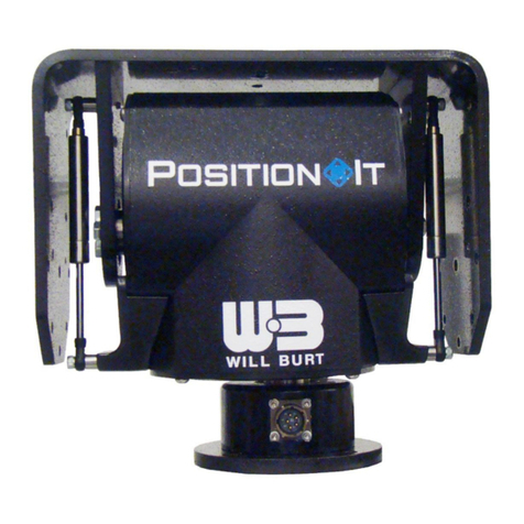
Will Burt PositionIt PI-35 User manual


POSITIONIT PI-35
TP-5406201-B i
July 2017
Warranty
The Company will repair or replace, if in its opinion, any part of the Goods which shall prove faulty
by reason of defect in workmanship or materials relating to the Goods which shall arise within 3
years of delivery to the Customer for mechanical items, (excluding wiper arms and blades), and
2 years forelectrical items, provided that anysuchfault is notified inWriting to theCompanywithin
10 working days of the date on which such fault was, or ought, reasonably to have been
discovered and provided that the Goods or relevant part thereof, if so requested by the Company,
are returned carriage paid by the Customer to the premises of the Company.
All works pursuant to the Guarantee shall be carried out by the Company free of charge to the
Customer except, if the cost of such works shall be increased by reason of any use of the Goods
after any fault ought reasonably to have been discovered, such increase shall be paid by the
customer.
If the work required is a result of misuse of the Goods by the Customer or any use of Goods after
any fault has been discovered, this Guarantee is rendered invalid.

POSITIONIT PI-35
ii TP-5406201-B
July 2017
Document History
Document Numbers
Dates
Remarks
TP-5406201-00
September 8, 2016
Initial Release
TP-5406201-A
November 21, 2016
Updated Figure 1-2. Updated Sections 2.7,
3.3.4.2, 3.4, and 7.
TP-5406201-B
July 19, 2017
Updated Section 1.6.1 and 1.5. Updated
Figures 1-1, 1-2, 1-3, 2-1, 2-2, 2-3, and 2-
14. Removed Top Level Drawing from
Section 7 and unnecessary drift
precaution.

POSITIONIT PI-35
TP-5406201-B iii
July 2017
Table of Contents
Section 1 Introduction.......................................................................................................... 1-1
1.1 Safety Precautions...........................................................................................................................1-1
1.2 How this Manual is Organized .........................................................................................................1-1
1.3 Additional Documentation................................................................................................................1-2
1.4 Definitions of Terms and Symbols ...................................................................................................1-2
1.5 Specifications...................................................................................................................................1-4
1.6 Major Components...........................................................................................................................1-5
1.6.1 Positioner..................................................................................................................................1-5
1.6.2 Controller...................................................................................................................................1-6
1.6.3 Power/Data Cable.....................................................................................................................1-7
1.6.4 Positioner Power Supply...........................................................................................................1-8
1.6.5 Step Up Converter ....................................................................................................................1-8
1.6.6 Step Down Converter................................................................................................................1-9
1.6.7 Barrel Connector (2.1 mm) .......................................................................................................1-9
1.7 Quick Overview..............................................................................................................................1-10
Section 2 Installation............................................................................................................ 2-1
2.1 Pre-Installation Check......................................................................................................................2-1
2.2 Installation Tools ..............................................................................................................................2-2
2.3 Components.....................................................................................................................................2-2
2.4 Unpacking ........................................................................................................................................2-2
2.5 Mounting the Positioner ...................................................................................................................2-3
2.6 Wiring the System............................................................................................................................2-4
2.6.1 Positioner Plugs........................................................................................................................2-4
2.6.2 Connecting Power and Controls...............................................................................................2-8
2.7 Mounting the Payload ....................................................................................................................2-12
2.8 Setting Presets and Electronic Limit Stops....................................................................................2-13
Section 3 Operation.............................................................................................................. 3-1
3.1 Pre-Operation Check .......................................................................................................................3-1
3.2 Operation Tools................................................................................................................................3-2
3.3 General Controls..............................................................................................................................3-2
3.3.1 Keyboard...................................................................................................................................3-3
3.3.2 Joystick .....................................................................................................................................3-3
3.3.3 Menu Functions.........................................................................................................................3-4
3.3.4 Presets......................................................................................................................................3-5
3.3.4.1 Setting Presets with the Keyboard.....................................................................................3-5
3.3.4.2 Recalling Presets with the Keyboard.................................................................................3-5
3.3.5 Electronic Limit Stops ...............................................................................................................3-6
3.3.5.1 Adjust Limit Stops with the Keyboard ................................................................................3-6
3.3.5.2 Restore Limit Stops with the Keyboard..............................................................................3-7
3.4 Unstowing the Positioner .................................................................................................................3-7
3.5 Stowing the Positioner .....................................................................................................................3-8
3.6 Transportation..................................................................................................................................3-8

POSITIONIT PI-35
iv TP-5406201-B
July 2017
Section 4 Maintenance ......................................................................................................... 4-1
4.1 Routine Maintenance .......................................................................................................................4-1
4.2 Replacement Parts...........................................................................................................................4-1
Section 5 Troubleshooting................................................................................................... 5-1
5.1 Troubleshooting Guide.....................................................................................................................5-1
5.2 Restoring Factory Defaults...............................................................................................................5-3
5.2.1 CamID.......................................................................................................................................5-3
5.2.2 MonID........................................................................................................................................5-3
5.2.3 Protocol.....................................................................................................................................5-4
5.2.4 Baud Rate .................................................................................................................................5-5
Section 6 Appendix............................................................................................................... 6-1
6.1 Communications Bridge Board Interface (optional).........................................................................6-1
6.1.1 Electrical Connections ..............................................................................................................6-1
6.1.2 Wire the Bridge Board Interface................................................................................................6-1
6.1.3 Set Stow and Unstow................................................................................................................6-3
6.1.3.1 With a Push Button Controller............................................................................................6-3
6.1.3.2 With a Toggle Switch Controller.........................................................................................6-3
6.2 Panel Mount Controller Assembly (optional)....................................................................................6-4
Section 7 Drawings............................................................................................................... 7-1
Table of Figures
Figure 1-1 Home Position .........................................................................................................................1-2
Figure 1-2 Positioner Directions................................................................................................................1-3
Figure 1-3 Positioner.................................................................................................................................1-5
Figure 1-4 Default Joystick Controller.......................................................................................................1-6
Figure 1-5 Power/Data Cable....................................................................................................................1-7
Figure 1-6 Positioner Power Supply .........................................................................................................1-8
Figure 1-7 Step Up Converter...................................................................................................................1-8
Figure 1-8 Step Down Converter ..............................................................................................................1-9
Figure 1-9 Barrel Connector......................................................................................................................1-9
Figure 2-1 Rear of Positioner....................................................................................................................2-3
Figure 2-2 Positioner Mounting Hole Pattern............................................................................................2-4
Figure 2-3 Positioner Plug Locations........................................................................................................2-4
Figure 2-4 Carefully Pull Out the Removable Plug, Gasket, and Attached Wires....................................2-5
Figure 2-5 Quick Connect.........................................................................................................................2-5
Figure 2-6 Remove the (4) Bolts Securing the Plug Plate........................................................................2-6
Figure 2-7 Remove Plug Plate and Gasket ..............................................................................................2-6
Figure 2-8 Pull the Wires out the Bottom of the Positioner.......................................................................2-7
Figure 2-9 Secure the Gasket and Removable Plug to the Bottom Egress .............................................2-7
Figure 2-10 Secure the Plug Plate and Gasket to the Side Egress..........................................................2-8
Figure 2-11 Powered with 12 VDC ...........................................................................................................2-9
Figure 2-12 Powered with 24 VDC .........................................................................................................2-10
Figure 2-13 Powered with VAC...............................................................................................................2-11

POSITIONIT PI-35
TP-5406201-B v
July 2017
Figure 2-14 Payload Mounting Hole Pattern...........................................................................................2-12
Figure 3-1 Keyboard Keys ........................................................................................................................3-3
Figure 3-2 Menu Screen ...........................................................................................................................3-4
Figure 5-1 Start Up Screen.......................................................................................................................5-3
Figure 5-2 Menu Screen ...........................................................................................................................5-4
Figure 5-3 Protocol Setup Screen.............................................................................................................5-4
Figure 5-4 Dome Screen............................................................................................................................5-4
Figure 5-5 Keyboard Setup Screen ..........................................................................................................5-5
Figure 6-1 Contact Closure.......................................................................................................................6-2
Figure 6-2 Panel Mount Controller (P/N: 4270601) ..................................................................................6-4
Table of Tables
Table 1-1 Positioner Specifications............................................................................................................1-4
Table 1-2 Default Joystick Controller (P/N: 5098901) Specifications.......................................................1-4
Table 1-3 Standard Cables.......................................................................................................................1-7
Table 2-1 Tools and Materials Recommended for Installation .................................................................2-2
Table 3-1 Tools and Materials Recommended for Operation...................................................................3-2
Table 3-2 Limit Stop Adjustment Numbers...............................................................................................3-6
Table 3-3 Default Limit Stop Numbers......................................................................................................3-7
Table 5-1 Troubleshooting the Positioner.................................................................................................5-1
Table 5-2 Troubleshooting the Controller .................................................................................................5-2
Table 5-3 Resetting the Protocol ..............................................................................................................5-4
Table 5-4 Resetting the Baud Rate...........................................................................................................5-5
Table 6-1 Contact Closure Wires..............................................................................................................6-2

POSITIONIT PI-35
vi TP-5406201-B
July 2017
Safety Summary
This section describes safety information for the PositionIt and its default joystick controller.
These are recommended precautions that personnel must understand and apply throughout
installation, operation, maintenance, and troubleshooting. Be sure to read and understand the
entire manual before performing any procedure outlined in this manual.
SIGNAL WORD DEFINITIONS
Warnings highlight an essential operating or maintenance procedure, practice, condition,
statement, etc., which, if not strictly observed, could result in injury to, or death of, personnel or
long-term health hazards.
Cautions highlight an essential operating or maintenance procedure, practice, condition,
statement, etc., which, if not strictly observed, could result in damage to, or destruction of,
equipment or loss of mission effectiveness.
Note: Notes highlight an essential operating or maintenance procedure, condition, or statement.
GENERAL SAFETY INSTRUCTIONS
The following are general safety precautions that are not related to any specific procedures.
These are recommended precautions that personnel must understand and apply throughout
installation, operation, maintenance, and troubleshooting. Additional precautions which apply to
specific procedures and steps may be listed with the procedure or step to which they apply.
Electrocution Hazard! Do not touch live wires. Make sure all power has been disconnected
prior to performing installation or maintenance. Make certain that the area is free of overhead
power lines and other unwanted sources of electricity. Do not operate the system during an
electrical storm. Follow OSHA safety regulations when working near energized power lines. Be
sure to allow sufficient clearance on all sides of the mast to allow for side sway. Death or
serious injury could result if proper precautions are not performed.
Safety Instruction –Lightning! Lightning protection is not part of this system. A proper means
of electrical grounding should be provided. Failure to observe this warning could result in death
or serious injury.
Resuscitation! Personnel working with or near high voltages should be familiar with modern
methods of resuscitation. Such information may be obtained from the Bureau of Medicine and
Surgery, United States Navy.

POSITIONIT PI-35
TP-5406201-B vii
July 2017
Pinch Point Hazard! Keep clear of moving parts. Be sure to stay clear of the positioner during
operation. Moving parts can crush and cut resulting in serious injury.
Crush Hazard! Do not stand directly beneath the positioner or payload. Be certain payload is
properly installed and secured. In locations or areas where the risk of injury occurs, or any part
of the assembly may become detached or fall for any reason, a strong safety chain or wire
hawser should be attached between the equipment and the mounting surface. At all times,
normal safety precautions must be employed. Death or serious injury could result if positioner
fails suddenly.
Safety Equipment! Helmets or hard hats, eye protection, gloves, and safety shoes or combat
boots must be properly worn while working in the deployment area. Death or serious injury
could result if proper safety equipment is not properly worn.
Trained Personnel Only! Installation, operation, and maintenance to be performed by trained
and authorized personnel only. Death or serious injury could result if proper installation,
inspection, operation, and maintenance procedures are not observed.
Lifting Hazard! Manually lifting over 55 lb. (25kg) is prohibited. In the UK, all lifting equipment
must be thoroughly examined annually by a competent person according to the Lifting
Operations and Lift Equipment Regulations 1998. Equivalent regulations exist in other EU
states.
Safety Instruction –Remote Control! The equipment is subject to remote control and may be
operated at any time. Persons working on the equipment should take appropriate precautions to
ensure that any unexpected movement does not occur as this could lead to injury.
Safety Instruction –Impact Loading! Utilize a safety tether to secure the payload in the event
of impact loading. The tether should connect to the positioner mounting pedestal or other rigid
structure. Death or serious injury could result if proper precautions are not performed.
Equipment Damage! All persons installing and maintaining this equipment should be suitably
qualified and work to national and local standards and codes of practice.

POSITIONIT PI-35
viii TP-5406201-B
July 2017
Equipment Damage! Each positioner contains a 1.85 amp self-resetting circuit breaker to
protect the PC board. Do not disassemble the positioner side plates, or separate from the
pedestal. Doing so will break the environmental seal and potentially cause improper stop limit
settings. This will void the warranty.
Safety Instruction –High Pressure Spray! Do not expose the positioner to high pressure
spray. Equipment damage may occur.

POSITIONIT PI-35
TP-5406201-B 1-1
July 2017
Section 1 Introduction
Review this manual in its entirety. Contact the Will-Burt Company with any questions before
performing any procedure outlined in this manual.
The PositionIt™system is a pan and tilt positioner system used as a platform for many different
applications. This system is designed to remotely position a suitable payload and may be
attached on top of a mast.
This manual covers the following PositionIt:
PI-35 (P/N: 5467801)
The PositionIt does not currently support the following:
GPS Control
Infrared Remote Control
RS-232 GUI Interface (customer supplied only)
Mast Up / Down Control
1.1 Safety Precautions
Refer to the Safety Summary for precautions to be observed while installing, operating,
maintaining, or troubleshooting this equipment.
1.2 How this Manual is Organized
This manual is organized into the following sections:
Section 1 Introduction
Section 2 Installation
Section 3 Operation
Section 4 Maintenance
Section 5 Troubleshooting
Section 7 Drawings

POSITIONIT PI-35
1-2 TP-5406201-B
July 2017
1.3 Additional Documentation
In addition to this manual, the controller ships with the controller manual. Reference this manual
for additional information on the function of the controller.
1.4 Definitions of Terms and Symbols
Throughout this manual, the following will be used:
General Terms:
Positioner refers to the PI-35 PositionIt
Controller refers to the default joystick controller (P/N: 5098901).
System refers to the entire positioner and Controller system.
Payload refers to the object or equipment being moved by the positioner.
Positions
Home (Figure 1-1) to refer to the factory set preset position [0] (zero) which is set to
move the positioner to the mid-point of both the pan and tilt. In this position, the tilt
platform will be horizontal, and the pan axis will be in the center position. In this position,
the rear of the positioner is the side facing the side egress on the mounting pedestal.
Note that the offset on the left of the positioner, as you face the side egress, is wider
than the offset to the right. The positioner ships in the home position.
Figure 1-1 Home Position
Side Egress
Note That the Left Offset
is Wider Than the Right

POSITIONIT PI-35
TP-5406201-B 1-3
July 2017
Stowed refers to a customer-set preset position which the positioner moves the payload
to a desired pan and tilt position for travel or safe storage. The customer should set this
as preset [1].
Unstowed refers to a customer-set preset position which the positioner moves the
payload to a desired pan and tilt position from the stowed position. The customer should
be sure the positioner can be safely moved to this position from the stowed position
without causing damage. The customer should set this as preset [2].
Directions
When operating the positioner, directions are given as follows:
Home Position
Top Down View
Figure 1-2 Positioner Directions
When using the default joystick:
oPushing the joystick forward will tilt the positioner towards the rear
oPulling the joystick back will tilt the positioner towards the front
oMoving the joystick to the right will rotate the joystick clockwise
oMoving the joystick to the left will rotate the joystick counterclockwise
Symbols:
Characters inside < > as in <Success!> represent text that appears on the display
screen.
Characters inside [ ] as in [1] represent buttons or keys being used.
Arrows as in “▲, ►, ▼, ◄” represent the direction(s) the positioner is moving in. These
arrows are shown on the display screen of the default joystick controller (P/N: 5098901).
Side Egress
Left
Right
Front
Rear (Side with
Side Egress)
Left
Right
Rotate Clockwise
Towards Right
Rotate
Counterclockwise
Towards Left
Move Up From Front
Move Down to Front

POSITIONIT PI-35
1-4 TP-5406201-B
July 2017
1.5 Specifications
Table 1-1 lists specifications for the positioner. Table 1-2 lists specifications for the default
joystick controller.
Table 1-1 Positioner Specifications
Functional Characteristic
Specification
Payload Capacity
35 ft.-lb. (47.4 Nm)
Overall Height
9.8 Inches (248 mm)
Overall Width
10.8 Inches (273 mm)
Approximate Weight
21 lb. (9.5 kg)
Operating Temperature
-4° to 122°F (-20° to 50°C)
Pan Axis
355° (± 177.5°)
Tilt Axis
180° (±90°)
Pan Speed (Proportional)
1 to 12° / Second
Tilt Speed (Proportional)
1 to 12° / Second
Backlash
<0.15°
Repeatability
<0.3°
Maximum Continuous Power
44 W
Maximum Continuous Current @ 24 VDC
1.85 A
Input Voltage
24 VDC
(Converters available for 12 VDC and AC power sources.)
Protocol
Pelco D used (Pelco P available)
Ingress Protection Rating
IP68 for dust and water intrusion
Baud Rate
2,400 bps
All dimensions and parameters are for reference only and are subject to change without notice.
Table 1-2 Default Joystick Controller (P/N: 5098901) Specifications
Functional Characteristic
Specification
Input Voltage
12 VDC
Rating Power
0.5 watts
Communication Interface
RS485
Communication Frequency
2,400 bps used (4,800; 9,600; 19,200 bps available)
Operating Temperature
32°F to 122°F (0°C to 50°C)
Dimensions (W x H x L)
5.4 x 4.2 x 6.6 in. (136 x 105 x 168 mm)
Weight
0.89 lb. (0.40 kg)
Protocol
Pelco D used
All dimensions and parameters are for reference only and are subject to change without notice.

POSITIONIT PI-35
TP-5406201-B 1-5
July 2017
1.6 Major Components
The major components of the system are:
Positioner
Controller
Power/Data Cable
Positioner Power Supply
Step Up Converter
Step Down Converter
1.6.1 Positioner
The PI-35 pan and tilt positioner:
Is made of die-cast aluminum casing
Uses stainless steel fasteners
Has weather and dust proofing to an IP68 rating
Is designed to minimize backlash
Is configured to run on RS485 data using Pelco D protocol
Contains an internal tether to prevent the pan and tilt head from separating from the
mast in the event of an impact load separating the pan and tilt head from the base
Ships with the PositionIt PI-35 Operator’s Manual (this manual)
Figure 1-3 Positioner
Payload
Platform
Removable Plug
on Side Egress
Mounting Pedestal
Bottom Egress Hidden on
Underside of Mounting Pedestal
Base
Pan and
Tilt Head

POSITIONIT PI-35
1-6 TP-5406201-B
July 2017
1.6.2 Controller
The default joystick controller (P/N: 5098901) (Figure 1-4):
Controls pan and tilt functions
Is Pelco D compatible
Has a joystick, LCD Screen and a keyboard
Has programmable presets
Has programmable electronic limits
Has speed control
Ships with the controller manual
Is not designed to handle inclement weather and should be kept in a protected
environment
Figure 1-4 Default Joystick Controller (Left: With Keyboard Cover On. Right: With Keyboard Cover Off.)
Joystick
LCD Screen
Keyboard
Keyboard
Cover

POSITIONIT PI-35
TP-5406201-B 1-7
July 2017
1.6.3 Power/Data Cable
The power/data cable (Figure 1-5) consists of (2) power wires (16 AWG twisted pair) and (2)
control wires (22 AWG twisted pair). The cable ships with a straight connector (PT06W14-5S)
installed on one end and loose wires on the other end to allow for a Nycoil pull. The end with the
loose wires can be cut if the customer requires a shorter length.
Figure 1-5 Power/Data Cable
Table 1-3 provides the part numbers for the standard cables.
Table 1-3 Standard Cables
Will-Burt
Part Number
Length
5195401
150 ft. (45.72 m)
5195402
100 ft. (30.48 m)
5195403
75 ft. (22.86 m)
5195404
50 ft. (15.24 m)
5195405
25 ft. (7.62 m)
Alternatively, the 90° elbow connector (P/N: 213227; PT08E-14-5S(SR)) may be purchased
separately for use with customer supplied wires.
Power/Data Cable
(P/N: 000018-500-001)
Connector
(P/N: 213261)

POSITIONIT PI-35
1-8 TP-5406201-B
July 2017
1.6.4 Positioner Power Supply
The positioner power supply (P/N: 208016) (Figure 1-6) is used in systems using 120 VAC
(50 or 60 Hz) or 240 VAC (50 or 60 Hz) to convert the AC power to 24 VDC input power for the
positioner. The power supply has short circuit, overcurrent, overvoltage, and over temperature
protections. It is an IP67 design and is suitable for dry, damp, or wet locations.
Figure 1-6 Positioner Power Supply
1.6.5 Step Up Converter
The step up converter (P/N: 208012) (Figure 1-7) is used in systems with 12 VDC input power
to step up the power to 24 VDC for the positioner.
Figure 1-7 Step Up Converter

POSITIONIT PI-35
TP-5406201-B 1-9
July 2017
1.6.6 Step Down Converter
The step down converter (P/N: 208017) (Figure 1-8) is used in systems with 24 VDC input
power to step down the power to 12 VDC to power the default joystick controller if the AC power
supply supplied with the joystick is not used to provide power.
Figure 1-8 Step Down Converter
1.6.7 Barrel Connector (2.1 mm)
The 2.1 mm barrel connector (P/N: 5195601) (Figure 1-9) can be used to connect the controller
to the step down converter or 12 VDC power source.
Figure 1-9 Barrel Connector

POSITIONIT PI-35
1-10 TP-5406201-B
July 2017
1.7 Quick Overview
This section provides a quick overview of the system. Be aware of and follow all associated
precautions when performing these procedures.
To install the positioner (Section 2 ):
1. Mount the positioner with (4) high-strength ⅜ in. or M8 stainless steel bolts and nuts.
See Section 2.5 for additional detail and bolt pattern.
2. Wire the positioner according to the schematic (Section 7). See Section 2.6 for additional
detail.
3. Mount the payload with appropriate hardware. See Section 2.7 for additional detail.
To operate the positioner (Section 3):
1. Attach the controller.
2. Operate the positioner using the controller. See Section 3 for additional detail on the
function of the default joystick controller (P/N: 5098901).
3. If required, see Section 3.3.4 for information on how to use preset positions.
4. If required, see Section 3.3.5 for information on how to adjust the electronic limit stops.
The positioner ships from the factory with electronic limit stops set. There are no hard
stops.
Table of contents
Other Will Burt Valve Positioner manuals