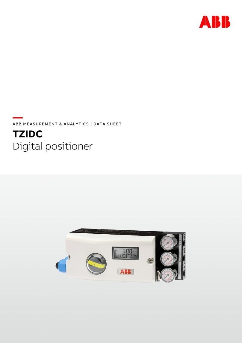
2 TZIDC, TZIDC-200 DIGITAL POSITIONER | COI/TZIDC/TZIDC-200-EN REV. B
Table of contents
1Safety..........................................................................4
General information and instructions..................................4
Warnings....................................................................................4
Intended use .............................................................................4
Improper use.............................................................................4
Cable glands..............................................................................4
Warranty provisions.................................................................4
Cyber security disclaimer .......................................................5
Software downloads ...............................................................5
Manufacturer’s address ..........................................................5
Service address.........................................................................5
2Operation ...................................................................6
Safety instructions...................................................................6
Parameterization of the device .............................................6
Menu navigation..................................................................6
Menu levels ................................................................................ 7
Operating modes ..................................................................... 7
Operating mode 1.0: Control with adaptation .............. 7
Operating mode 1.1: Control without adaptation......... 7
Operating mode 1.2: Manual adjustment in the stroke
range......................................................................................8
Operating mode 1.3: Manual adjustment in the sensor
range......................................................................................8
Locks...........................................................................................9
3Configuration...........................................................10
General information...............................................................10
Example....................................................................................10
Parameter description HART® ............................................. 11
HART parameter overview (graphic) ..................................14
Parametergroup 1: Standard................................................ 15
ACTUATOR – actuator type ............................................. 15
AUTO_ADJ – Automatic adjustment .............................. 15
ADJ_MODE – Automatic adjustment mode..................16
TEST – Test .........................................................................16
FIND_DEV – find device .................................................... 17
EXIT – Back to work level.................................................. 17
Parameter group 2: Set point............................................... 17
MIN_RGE – min. set point range ..................................... 17
MAX_RGE – max. set point range ................................... 17
CHARACT – characteristic curve .....................................18
ACTION – direction of action (setpoint signal)............ 18
SHUT_CLS – Shut-off value 0 % ...................................... 18
SHUT-OPN – Shut-off value 100 % ................................. 18
RAMP UP – set point ramp (up)....................................... 19
RAMP DN – Set point ramp (down) ................................19
EXIT – Back to work level..................................................19
Parameter group 3: Working range.....................................20
MIN_RGE – min. operating range....................................20
MAX_RGE – max. operating range ..................................20
ZERO_POS – zero point position .................................... 21
EXIT – Back to work level.................................................. 21
Parameter group 4: Messages ............................................ 22
TIME_OUT – stroke time monitoring............................. 22
POS_SW1 – switching point SW1 .................................... 22
POS_SW2 – switching point SW2 ................................... 22
SW1_ACTV – Active Direction SW1 ................................. 23
SW2_ACTV – Active Direction SW2................................. 23
EXIT – Back to work level ................................................. 23
Parameter group 5: Alarms .................................................. 24
LEAKAGE – Leakage to actuator .................................... 24
SP_RGE – set point monitoring ...................................... 24
SENS_RGE – operating range up-scaled ....................... 24
CTRLER – controller inactive ........................................... 24
TIME_OUT – stroke time monitoring............................. 25
STRK_CTR – Movement counter..................................... 25
TRAVEL – travel counter................................................... 25
EXIT – Back to work level ................................................. 25
Parameter group 6: Manual adjustment ........................... 26
MIN_VR - min. working range.......................................... 26
MAX_VR – max. operating range .................................... 26
ACTUATOR – actuator type ............................................. 27
SPRNG_Y2 – spring action (Y2)....................................... 27
DANG_DN – Dead Angle Close ........................................ 27
DANG_UP – Dead Angle Open......................................... 27
BOLT_POS - actuator bolt position ............................... 27
EXIT – Back to work level ................................................. 28
Parameter group 7: Controller parameters....................... 28
KP UP – KP value (up)........................................................ 28
KP DN – KP value (down).................................................. 29
TV UP – TV value (up)........................................................ 29
TV DN – TV value (down).................................................. 29
Y-OFS UP – Y offset (up) ..................................................30
Y-OFS DN – Offset (down)...............................................30
TOL_BAND – Tolerance band ...........................................31
DEADBAND – Dead band...................................................31
DB_APPR – Deadband Approach .....................................31
DB_CALC – Deadband Determination............................31
LEAK_SEN – Leak Sensitivity........................................... 32
EXIT – Back to work level ................................................. 32
Parameter group 8: Analog output .................................... 32
MIN_RGE – Current range min. ....................................... 32
MAX_RGE – Current range max. ..................................... 32
ACTION – Direction of action of the characteristic
curve.................................................................................... 32
ALARM – Alarm................................................................... 33
RB_CHAR – Calculate back to characteristic................ 33
TEST – Test......................................................................... 33
ALR_ENAB – Alarm through the analog output ........... 33
CLIPPING – Extending the signal output range........... 33
EXIT – Back to work level ................................................. 34
