manuals.online logo
Brands
  1. Home
  2. •
  3. Brands
  4. •
  5. WILLAMS SOUND
  6. •
  7. Hearing Aid
  8. •
  9. WILLAMS SOUND SoundPlus WIR TX925 User manual

WILLAMS SOUND SoundPlus WIR TX925 User manual

SoundPlus™
Infrared Listening System
Quick Setup Guide
Two-Channel Configuration, WIR TX925, WIR SYS 1, WIR SYS 4
CHA
AUDIO IN
CHB
AUDIO IN
AUDIO
OUTPUT
POWER ON
INDICATOR
MOD 232 MODULATOR (REAR)
BASEBAND
OUTPUT
BASEBAND
OUTPUT
BASEBAND
INPUT
BASEBAND
INDICATOR
TO ADDITIONAL EMITTERS
(IF NECESSARY)
WIR TX9 EMITTER (REAR)
RX22-4 RECEIVERS
(WIRELESS)
A264
Power On Baseband On
Multi-Channel Infrared Transmitter
Made in U.S.A.
24 VACNC
CAUTION
RISK OF ELECTRIC SHOCK
DO NOT OPEN
WARNING: TOREDUCE THE RISK OF FIRE OR
ELECTRIC SHOCK DO NOT EXPOSE THIS
EQUIPMENT TO RAIN OR MOISTURE.
Power In:
24VAC
50-60Hz
35VA
Power Supply Wiring:
Baseband Signal Wiring:
Note: It is normal for this unit to feel warm while it is in operation.
Plug
Use NEC, Class 2 Wiring, 18 ga. minimum,
200 ft. (70m) maximum length (18 ga.)
Use 50 Ohm Coaxial Cable (RG58)
Use RG58 Coax,1000 ft. (350m) max. length
www.williamssound.com
InOut Out
50 Ohms
Baseband
(Modulation)
~
Mounting
Bracket
RoHS
Class 1
LED Product
Williams Sound, Minneapolis, Minnesota, USA
Patent Pending
POWER IN
120 AVC (US): TFP 010
230 VAC (CE): TFP 027
POWER IN
120 AVC (US): TFP 010
230 VAC (CE): TFP 027
Figure 1: Typical 2-channel conguration when
using the MOD 232 Modulator, TX9 Emitter, and
optional RX22-4 Receiver.
Refer to installation manual for detailed descriptions and set-up procedures.
Modulator Set-Up
1. Position the MOD 232 Modulator near the sound system or mixer from which it will receive audio.
2. Connect the power supply to the 3-pin Molex connector located in the back of the MOD 232. A green LED will
illuminate on the front of the MOD 232 when the power switch is in the “On” position.
3. Audio connection: The MOD 232 Modulator will accept a microphone using 3-pin male connector, or a 1/4” phone
plug with a balanced or unbalanced line level signal. Connect the sound system accordingly to the audio inputs in the
back of the MOD 232 labeled “Input CHA” and “Input CHB.”
4. The MOD 232 Modulator has four selectable frequencies to choose from: 2.3, 2.8, 3.3, 3.8 MHz. This system is
preset to 2.3 and 2.8 MHz. Frequency selection can be adjusted by using the “Conguration Switches” located on the
back of the MOD 232.
5. Prepare the MOD 232 to be connected to the TX9 emitter. Determine the length of RG-58 cable needed to reach from
the emitter to the Modulator unit. Install BNC connectors to each end of the cable.
MAN 133D
3
SoundPlus™Infrared Listening System
MAN 133D
TX9 Emitter Set-up
1. Determine the coverage area needed for the seating area. When using the RX22-4 receiver, one TX9 will cover an area of
28,000 sq. ft. (2,600 sq. m.) in single channel mode. In two-channel mode, one TX9 will cover an area of approximately 18,000
sq. ft. (1,700 sq. m.). In four-channel mode, the coverage area is approx. 11,000 sq. ft. (1,000 sq. m.). Coverage area will vary
depending on the sensitivity of the infrared receiver being used. See coverage drawings in the manual (MAN 132). To determine
how many TX9 emitters are required for 100% coverage of the listening area, we recommend performing a site test.
2. Determine placement and location for the TX9. Ideally, the emitter should be located high enough so not to interfere with people
or other obstructions. Mount the emitter at least 2 ft. (.61 m) above the audience. The TX9 may need to be angled slightly
downward to maximize the coverage area. Wall and ceiling mount brackets are available for permanent installation of the TX9.
Emitter stands are available for portable applications.
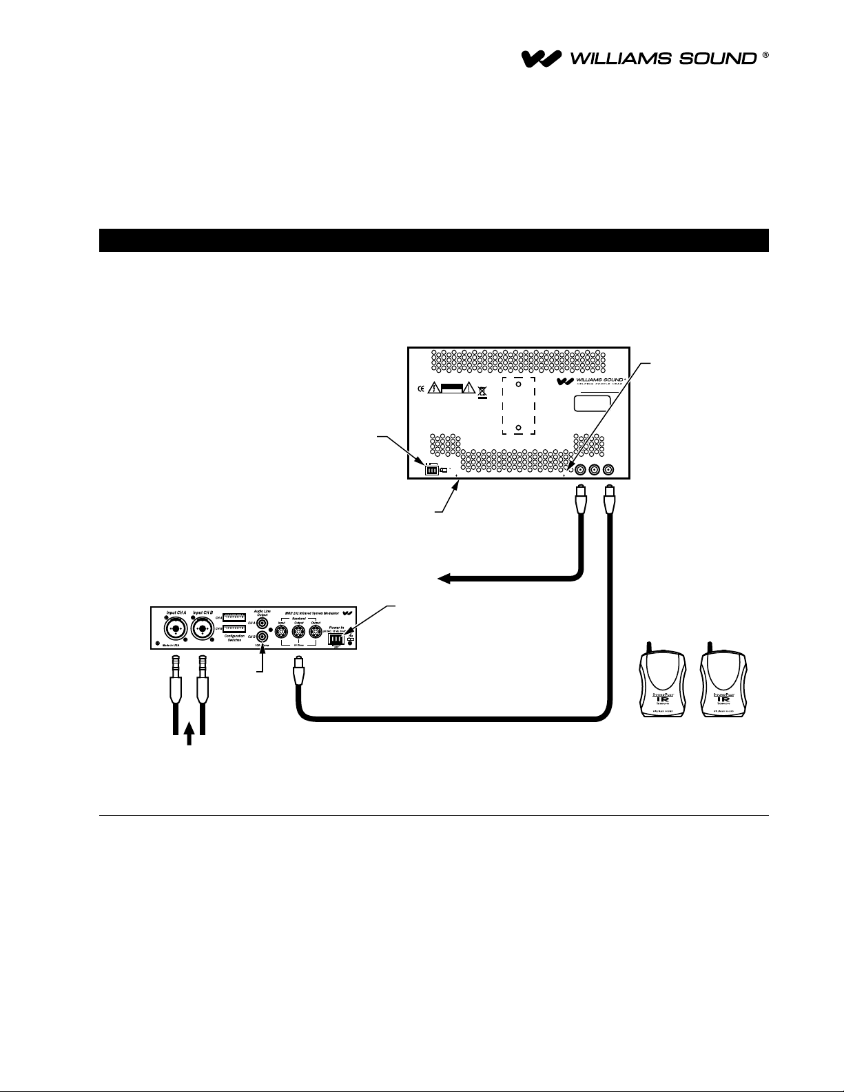
3. Connect the power supply to the 3-pin Molex connector located in the back of the TX9. When power is supplied to the TX9
emitter, a green LED indicator will be visible underneath the unit. When the baseband is activated, a red LED indicator will be
visible underneath the unit.
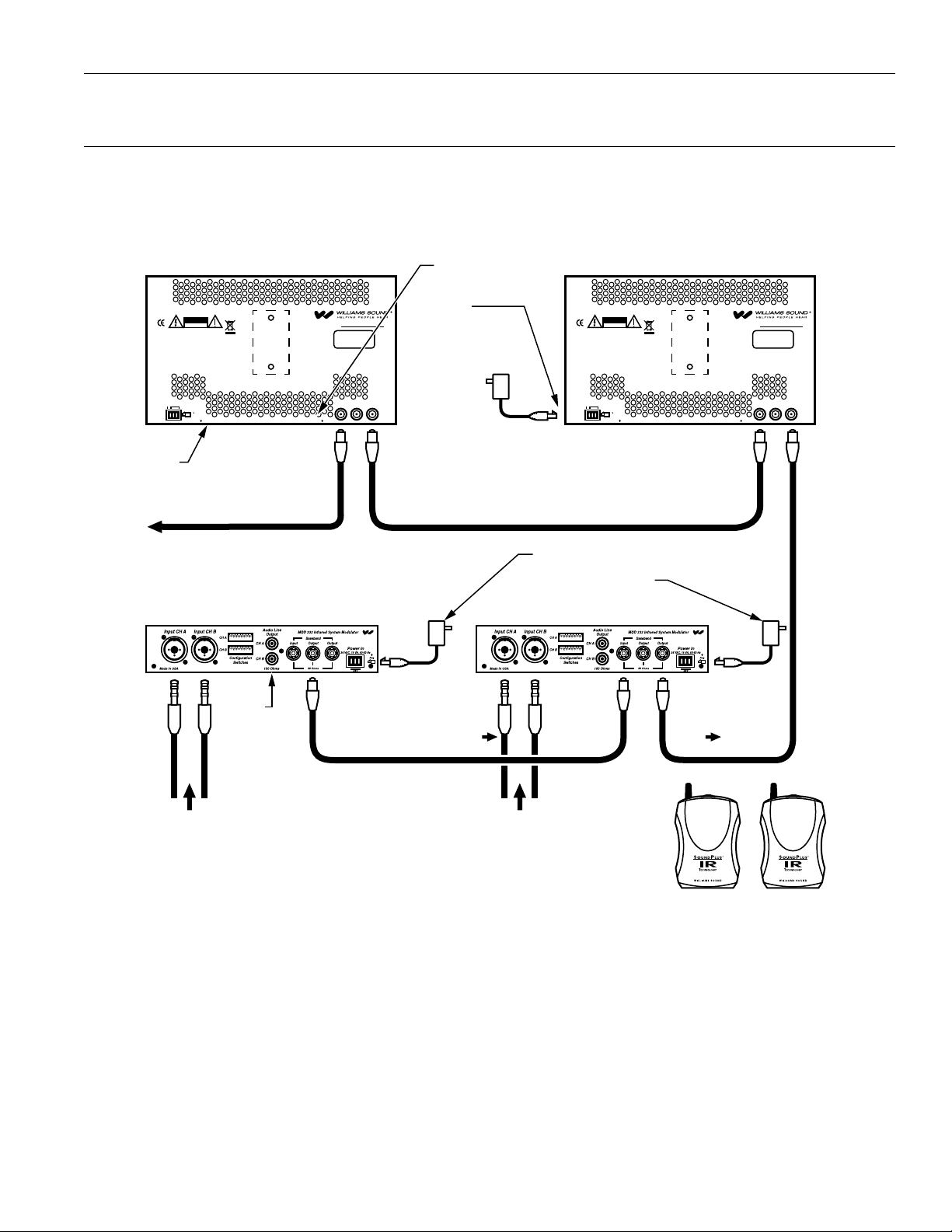
4. Connect the baseband cable to the “Baseband Out” jack in the rear of the MOD 232, then connect the cable to the “Baseband
Input” jack in the rear of the TX9 emitter. Additional TX9 emitters can be linked together as needed for coverage. See Figure 1.
RX22-4 Receiver Set-up
The RX22-4 comes standard with 2 AA alkaline batteries.
1. Plug in an earphone or headphone in the jack on top of the unit.
2. Rotate the receiver on/off/volume switch to turn the receiver on. A red “on” indicator
will illuminate on top of the unit. Adjust the volume control to a comfortable listening
level.
3. Turn the channel selector knob on the top of the unit to select from 2.3 MHz (Ch. 1),
2.8 MHz (Ch. 2), 3.3 MHz (Ch. 3), or 3.8 MHz (Ch. 4).
4. The RX22-4 can be tested by holding it up to the infrared emitter labeled “IR” on the
front of the MOD 232 Modulator.
NOTE: Make sure the “SoundPlus® IR” artwork is facing the TX9 emitter (Figure
2). The front of the RX22-4 should not be covered; do not place the receiver
in pants or shirt pocket. Do not obstruct the light path between the RX22-4
Receiver and the TX9 emitter or the unit will not function properly. See manual
for additional receiver instructions (MAN 132).
Quick Set-up Trouble Shooting
• Is the sound system on and audio source active?
• Are the power cables for the Emitter and Modulator secured and plugged in?
• Are the power switches for the Modulator and Receiver in the “On” position?
• Are the “On” LED indicators visible on the Emitter, Modulator and Receiver?
• Are the baseband cables connected to the correct input/output jack?
• Is the baseband LED “On” indicator illuminated underneath the Emitter?
• Are the correct frequencies selected on the Modulator?
• Are there obstructions between the Emitter signal and the Receiver?
• Are the batteries in the Receiver installed and working?
RX22-4 FRONT
RX22-4 TOP
ON/OFF
VOLUME SWITCH
A137
EARPHONE
JACK
"ON"
INDICATOR
CHANNEL
SELECTOR
OFF
RX22-4 FRONT
RX22-4 TOP
ON/OFF
VOLUME SWITCH
A137
EARPHONE
JACK
"ON"
INDICATOR
CHANNEL
SELECTOR
OFF
Figure 2: RX22-4 Top and Front
4
SoundPlus™Infrared Listening System
MAN 133D
CHA
AUDIO IN
CHB
AUDIO IN
SOUND SYSTEM
MOD 232 MODULATOR (REAR)
BASEBAND SIGNAL
CHA
AUDIO IN
CHB
AUDIO IN
SOUND SYSTEM
MOD 232 MODULATOR (REAR)
TO ADDITIONAL EMITTERS
(IF NECESSARY)
WIR TX9 EMITTER (REAR)
RX22-4 RECEIVERS
(WIRELESS)
A265
Power On Baseband On
Multi-Channel Infrared Transmitter
Made in U.S.A.
24 VACNC
CAUTION
RISK OF ELECTRIC SHOCK
DO NOT OPEN
WARNING: TOREDUCE THE RISK OF FIRE OR
ELECTRIC SHOCK DO NOT EXPOSE THIS
EQUIPMENT TO RAIN OR MOISTURE.
Power In:
24VAC
50-60Hz
35VA
Power Supply Wiring:
Baseband Signal Wiring:
Note: It is normal for this unit to feel warm while it is in operation.
Plug
Use NEC, Class 2 Wiring, 18 ga. minimum,
200 ft. (70m) maximum length (18 ga.)
Use 50 Ohm Coaxial Cable (RG58)
Use RG58 Coax,1000 ft. (350m) max. length
www.williamssound.com
InOut Out
50 Ohms
Baseband
(Modulation)
~
Mounting
Bracket
RoHS
Class 1
LED Product
Williams Sound, Minneapolis, Minnesota, USA
Patent Pending
WIR TX9 EMITTER (REAR)
Power On Baseband On
Multi-Channel Infrared Transmitter
Made in U.S.A.
24 VACNC
CAUTION
RISK OF ELECTRIC SHOCK
DO NOT OPEN
WARNING: TOREDUCE THE RISK OF FIRE OR
ELECTRIC SHOCK DO NOT EXPOSE THIS
EQUIPMENT TO RAIN OR MOISTURE.
Power In:
24VAC
50-60Hz
35VA
Power Supply Wiring:
Baseband Signal Wiring:
Note: It is normal for this unit to feel warm while it is in operation.
Plug
Use NEC, Class 2 Wiring, 18 ga. minimum,
200 ft. (70m) maximum length (18 ga.)
Use 50 Ohm Coaxial Cable (RG58)
Use RG58 Coax,1000 ft. (350m) max. length
www.williamssound.com
InOut Out
50 Ohms
Baseband
(Modulation)
~
Mounting
Bracket
RoHS
Class 1
LED Product
Williams Sound, Minneapolis, Minnesota, USA
Patent Pending
AUDIO
OUTPUT
POWER ON
INDICATOR
BASEBAND
OUTPUT
BASEBAND
INPUT
BASEBAND
OUTPUT
BASEBAND
INPUT
POWER IN
120 AVC (US): TFP 010
230 VAC (CE): TFP 027
POWER IN
120 AVC (US): TFP 010
230 VAC (CE): TFP 027
BASEBAND
INDICATOR
Figure 3: Typical 4-channel conguration when using (2) MOD 232 Modulator, TX9 Emitter, and optional RX22-4 Receivers.
Four-Channel Conguration
WIR TX900, WIR SYS 4
1. Use the WCA 068 short coaxial cable (Figure 3 above) to link the two MOD 232 Modulators.
2. Connect the short coaxial cable to the “Baseband Output” jack of the rst MOD 232 in the chain. Connect the other end of the
short coaxial cable to the “Baseband Input” jack of the second MOD 232 in the chain.
3. Each modulator is set-up to accept two audio inputs. When the modulators are linked, they can accept a total of four audio
inputs. Connect the input signals to the audio inputs in the back of the MOD 232 labeled “Input CHA” and “Input CHB.”
Frequencies are pre-set to 2.3, 2.8, 3.3, 3.8 MHz. Frequency selection can be adjusted by using the “Conguration Switches”
located on the back of the MOD 232 (see page 4).
4. Wiring the Modulator to the TX9 Emitter: Connect a coaxial cable to the “Baseband Output” jack of the second MOD 232 in the
chain. The other end of the coaxial cable will connect to the “Baseband Input” jack of the TX9. Additional TX9 Emitters can be
linked together as needed for coverage see Figure 3.
MAN 133D
SoundPlus™Infrared Listening System
©2012 Williams Sound • All Rights Reserved
10300 Valley View Rd • Eden Prairie, MN 55344
800-328-6190 / 952-943-2252 • FAX: 952-943-2174
www.williamssound.com
Conguration Settings
The diagram below (Figure 4) illustrates how to congure your system using the switch settings (Figure 5) on the back of the MOD
232 Modulator. This diagram is also printed on top of the MOD 232 Modulator for quick reference.
A250
Figure 4: DIP Switch Conguration Chart
CHANNEL A AND B
CONFIGUREATION
SWITCHES
A252
Figure 5: Conguration Switches on Back of MOD 232.

This manual suits for next models

2

Popular Hearing Aid manuals by other brands

LIFEBOX Bluedot B-HA02 user manual

LIFEBOX

LIFEBOX Bluedot B-HA02 user manual

Audina SPARO Fittings guide

Audina

Audina SPARO Fittings guide

Starkey Evolv AI quick start guide

Starkey

Starkey Evolv AI quick start guide

Sona vogue ric 700 user guide

Sona

Sona vogue ric 700 user guide

Siemens SecureEar user guide

Siemens

Siemens SecureEar user guide

Rion HB-M1 quick guide

Rion

Rion HB-M1 quick guide

Starkey Livio R quick start guide

Starkey

Starkey Livio R quick start guide

Siemens ePen user guide

Siemens

Siemens ePen user guide

ReSound f861-drw manual

ReSound

ReSound f861-drw manual

Siemens Life user guide

Siemens

Siemens Life user guide

Amplicom NL 200 operating instructions

Amplicom

Amplicom NL 200 operating instructions

Audifon MULTISTREAMER PRO user manual

Audifon

Audifon MULTISTREAMER PRO user manual

ReSound MATCH BTE Technical manual

ReSound

ReSound MATCH BTE Technical manual

Cochlear Baha BI300 instructions

Cochlear

Cochlear Baha BI300 instructions

Siemens INTUIS Life user guide

Siemens

Siemens INTUIS Life user guide

Rexton Gem user guide

Rexton

Rexton Gem user guide

Siemens IT user guide

Siemens

Siemens IT user guide

Coselgi D-CIC-M TR User instructions

Coselgi

Coselgi D-CIC-M TR User instructions

manuals.online logo
manuals.online logoBrands
  • About & Mission
  • Contact us
  • Privacy Policy
  • Terms and Conditions

Copyright 2025 Manuals.Online. All Rights Reserved.