WilliamsRDM 8155-1 User manual

WilliamsRDM, Inc. 1 | P a g e
8155-1 Solar Tester User Manual
August 27, 2021

WilliamsRDM, Inc. 2 | P a g e
1 Overview
The WilliamsRDM Solar Tester (Figure 1) is built to test the voltage, current and power output of the
WilliamsRDM covert solar devices and other equivalent solar systems. The tester can be used to verify proper
operation and wiring of repaired cables and solar panels. It can also be used to measure the performance of the
solar panels in a deployed location to verify operation and power output. Using the optional paint adapter kit,
the solar tester can be used as a guide to apply WilliamsRDM’s custom formulated paint to the covert solar
devices in the field without the fear of over painting and thus degrading the solar devices.
Figure 1: WilliamsRDM 8155-1 Solar Tester
Key Features
Interfaces with WilliamsRDM Covert Solar Devices and Equivalent Solar Products.
Intuitive User Interface
Measures Standard Solar Panel Parameters
o Open Circuit Voltage
o Short Circuit Current
o Maximum Power Point Voltage, Current and Power
Allows testing of field repaired solar devices
Max Input Voltage: 50V
Max Input Current: 1A
Max Power: 12W
Built in overload protection
Uses standard AA Alkaline Batteries
Easy to read backlit LCD display.
15-minute auto power off

WilliamsRDM, Inc. 3 | P a g e
2 Solar Tester
The Solar Tester is shown in Figure 2. The tester has three buttons for the user interface and a backlit LCD for
easy readability in all lighting conditions. The device has two connectors for testing various solar products, the
“TEST” port and the “AUX” port. The “TEST” port is used to test WilliamsRDM Smart solar devices while the
“AUX” port is used to test WilliamsRDM and equivalent standard solar devices and solar panels. The unit is
powered on by pressing the “SELECT” button and powered off by pressing and holding the “SELECT” button for
about 2 seconds. The Up/Down arrows are used to navigate the menu system and the “SELECT” button is used
to select a test as well as to exit from a test back to the main menu.
Figure 2: Solar Tester
Once powered on the version screen is displayed for several seconds then the tester displays the menu system
as show in Figure 3. The up and down arrows control the cursor and are used to select the desired test. The scroll
indicator tells the user that there are additional tests above or below the displayed menu items. The display will
scroll up or down as needed to allow the user to reach the desired test. Once the cursor is pointing to the desired
test the “SELECT” button is used to start the test. The test port indicator identifies which port the test will be
performed on. The [T] indicates the TEST port will be used while the [A] indicates that the AUX port will be used.
The user will select the test with the connector that mates with the solar product they are trying to test. Once
the test is complete the “SELECT” button is then used to exit from the test back to the main menu to select a
different test.

WilliamsRDM, Inc. 4 | P a g e
Figure 3: Main Menu Screen
3 Display Contrast Adjustment
If the Solar Tester Display is too light or dark the contrast can be adjusted by selecting the “Contrast” option on
the menu screen. Once the Contrast option is selected the contrast adjustment screen is displayed as shown in
Figure 4. The screen contrast can then be adjusted using the up and down arrows. Once the desired display
contrast is reached press the “SELECT” button to exit back to the main menu. The contrast setting will be saved
once it is set.
Figure 4: Contrast Adjustment Screen
Cursor
Test Name Test Port Indicator
TEST/AUX Port
Scroll
Indicator

WilliamsRDM, Inc. 5 | P a g e
4 Battery Indicator
The Battery indicator is shown in the upper right corner of the display on any test screen (see Figure 5). The
battery indicator provides a visual indication of the remaining battery capacity so that the user can replace the
batteries before they are exhausted. The batteries should provide several hours of operation. Additionally, If the
tester is left on it will automatically power off after 15 minutes of inactivity to conserve power.
Figure 5: Battery Indicator
When the batteries are exhausted the low battery screen will be displayed as shown in Figure 6 and the solar
tester will automatically power off. At this time the batteries must be replaced to use the tester again.
Figure 6: Low Battery Screen
Battery
Indicator

WilliamsRDM, Inc. 6 | P a g e
5 Battery Replacement
The solar tester is powered from 4 standard AA alkaline batteries which can be easily replaced by the user.
Always use new AA alkaline batteries of the same brand in the solar tester. When replacing batteries don’t mix
and match batteries of different brands or new and old batteries. To replace the batteries, remove the battery
covert from the back of the solar tester and replace the batteries. Figure 7 shows the orientation of the batteries
within in the battery holder.
Figure 7: Battery Installation
6 Supported Tests
The solar tester is designed to test solar panels in sunlight. The tester will not work indoors with solar panels
illuminated with fluorescent or LED lighting. The following tests are supported by the Solar Tester:
1) Contrast Adjustment
2) Basic Solar Panel [A] (Aux Port)
a. Tests Standard Covert Solar Devices via the AUX port
3) Basic Solar Panel [T] (Test Port)
a. Tests Standard Covert Solar Devices using the AUX port
b. Tests Smart Solar Devices in Basic Mode
4) Smart 12V Solar Panel [T] (Test Port)
a. Tests Smart Solar Devices with integrated 12V solar charger
5) Paint Test [A] (Aux Port) – Requires Paint Test Adapter Kit
a. For Painting WilliamsRDM Standard Solar Devices
6) Paint Test [T] (Test Port) – Requires Paint Test Adapter Kit
a. For Painting WilliamsRDM Smart Solar Devices
7) Reference Panel [A] (Aux Port) – Requires Paint Test Adapter Kit
+
+
+
+
-
-
-
-

WilliamsRDM, Inc. 7 | P a g e
a. Tests the Reference Panel and Aux Port Adapter
8) Reference Panel [T] (Test Port) – Requires Paint Test Adapter Kit
a. Tests the Reference Panel
7 Basic Solar Panel Test
The basic solar panel test is used to test the WilliamsRDM Standard Covert Solar devices as well as other
equivalent solar panels. Additionally, WilliamsRDM Smart solar rocks can be tested in basic solar mode using the
“TEST” port. This is done for applications where the smart solar rock is being used with an external battery
charger and bypassing its internal charger. The basic solar panel test should be performed outside on a sunny
day to measure the maximum output power of the solar device. The tester can also be used to test the output
of a deployed solar device to measure the actual power output in the deployed location with the actual lighting
conditions.
Figure 8 shows an example test screen for the basic solar test on the “AUX” port which is used for the
WilliamsRDM standard solar devices. The solar tester reports several solar panel test parameters to ensure the
solar panel is working properly. Table 1 shows and example of the test parameters provided by the solar tester
for the basic solar test as well as their definitions and a brief description of their meaning.
Figure 8: Basic Solar Test Screen
Test Name Test Port

WilliamsRDM, Inc. 8 | P a g e
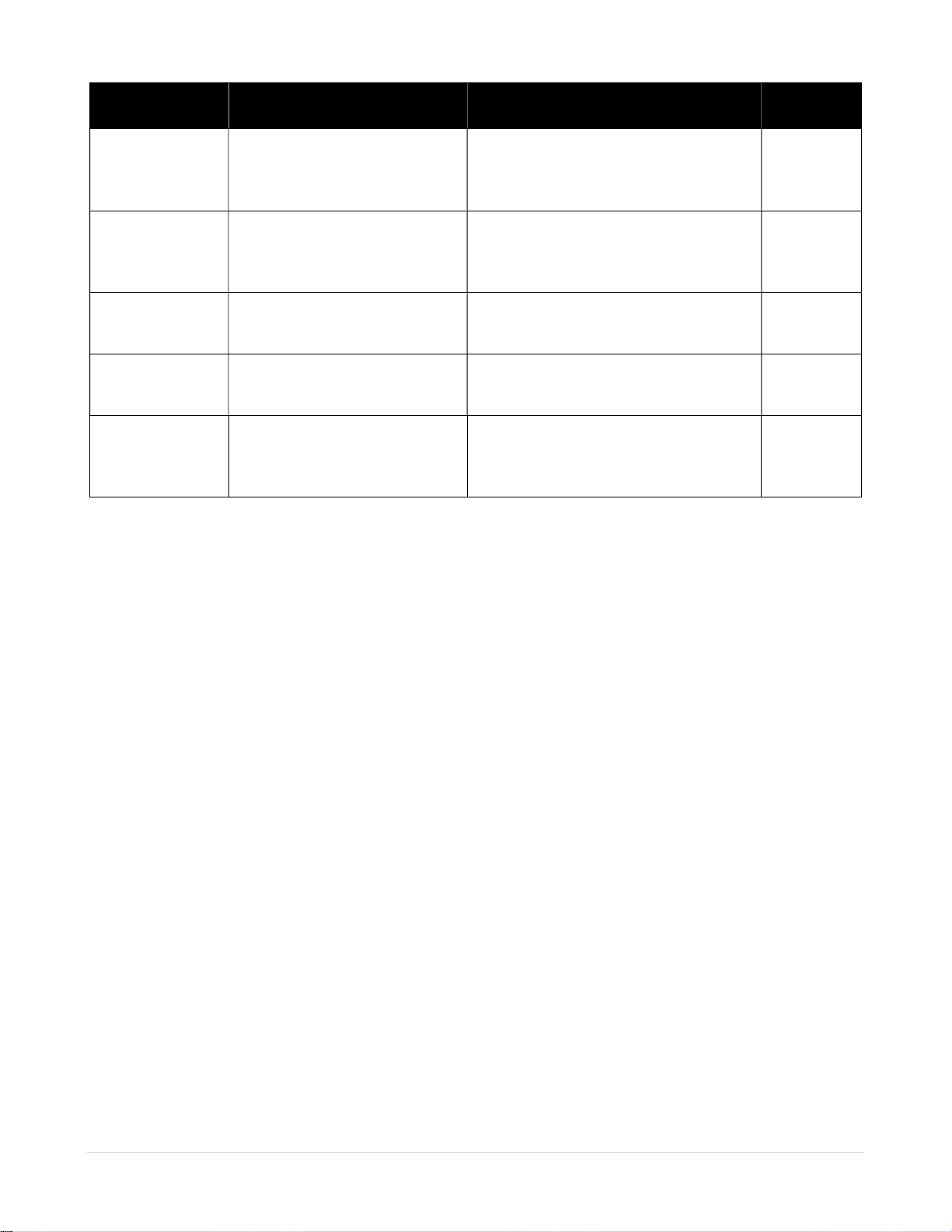
Table 1: Basic Solar Test Parameters
Symbol Definition Description Value
Vo Open Circuit Voltage Open Circuit Voltage that would be
measured from solar panel with a
multimeter
19.4V
Is Short Circuit Current Short Circuit Current that would be
measured from a solar panel with a
multimeter
168mA
Vm Maximum Power Point Voltage The voltage at which the solar panel
produces its maximum output power
17.7V
Im Maximum Power Point Current The current at which the solar panel
produces its maximum output power
139mA
Pm Maximum Power Point power The maximum power the solar panel can
produce if loaded at its maximum power
point voltage and current
2.4W
From a user perspective the most important parameter to consider is the Pm (Maximum Power) parameter
which measures the maximum power that the solar panel can output when properly loaded in a particular
lighting condition. The output power in full sun with the sun directly overhead should be close to the rating of
the solar panel that is being tested otherwise the panel may not be working properly. For example, if a 5W solar
rock is being tested in full sun and only producing 0.2W then the solar panel may not be working properly.
If multiple solar devices are connected in parallel with a Y-Adapter, then the measured output power should be
approximately the sum of each individual solar device.
8 Smart 12V Test
The Smart 12V Test is used to test the WilliamsRDM Covert Smart Solar Devices which incorporate a Maximum
Power Point Tracking (MPPT) Solar Charger, Partial Shading technology and are designed to charge 12V lead acid
batteries. This test should be performed outside on a sunny day to measure the maximum power from the Smart
Solar Device. The Smart 12V Test provides information on the battery charging voltage, current, power as well
as a pass/fail indicator for the smart solar device. Table 2 shows and example of the test parameters provided
by the solar tester for the Smart 12V Test as well as their definitions and a brief description of their meaning.

WilliamsRDM, Inc. 9 | P a g e
Figure 9: Smart 12V Solar Test Screen
Table 2: Smart 12V Solar Test Parameters
Symbol Definition Description Value
V Battery Charge Voltage The is the maximum charging voltage
(float voltage) for the battery.
13.7V
I Battery Charging Current The current that the solar panel is
providing to charge the battery
316mA
P Battery Charging Power The power the solar panel is providing to
charge the battery
3.7W
Test Result Smart Solar Panal Test Result Panel OK – Smart Solar Panel OK
Fail: Low Voltage – Low Charging Voltage
Fail: High Voltage – High Charging Voltage
Increase Sunlight – Test Requires More Light
See
Description
From a user perspective the main things to check for is that the Panel OK message is displayed, and the power
output is in an acceptable range for the given lighting conditions and rated output power. If multiple solar
devices are connected in parallel with either Y-Adapter or daisy chained together then the measured output
power should be approximately the sum of each individual solar device and the status should read Panel OK.
Test Name Test Port
Test Result

WilliamsRDM, Inc. 10 | P a g e
9 Paint Test (Requires Optional Solar Paint Adapter Kit)
To provide the ability for a user to field paint the WilliamsRDM Covert Solar Devices an optional Solar Paint
Adapter Kit is available for the Solar Tester to assist in the painting process. While it is desirable to be able to
custom paint the WilliamsRDM solar devices in the field there is a danger of over painting the solar panels. The
Solar Paint Test of the Solar Tester provides a guide while painting to show the user how much paint to apply to
the solar panel. (NOTE: WilliamsRDM custom formulated paint is required to paint the covert solar devices)
The Solar Paint Adapter Kit shown in Figure 10 includes the Reference Panel and the AUX Port Adapter. The
reference panel is used as a light reference for the paint test. It compensates for different lighting conditions,
time of day, light cloud cover, slight orientation differences etc. to allow for a consistent paint application across
various lighting conditions. The AUX Port Adapter is used to connect the Reference Panel to the AUX port when
painting WilliamsRDM Smart Solar Devices.
Figure 10: Optional Solar Paint Adapter Kit
9.1 Paint Procedure
Specially formulated WilliamsRDM paint is required to paint the Covert Solar Devices. The paint is formulated to
add camouflage while still allowing the wavelengths of light required for solar panel operation. Painting should
be performed outside on a sunny day with no clouds. The reference panel will compensate for changing lighting
conditions and light cloud cover but, for best results painting should be performed on a clear sunny day. The
paint test needs to be done outdoors, the test will not work indoors with fluorescent or LED lighting since these
lights do not emit the correct wavelength of light for solar panel operation. The covert solar devices to be painted
should be connected to the appropriate port on the solar tester and the reference panel connected to the
Reference
Panel
AUX Port
Adapter

WilliamsRDM, Inc. 11 | P a g e
opposite port using the AUX port adapter if needed. Sections 9.2 and 9.3 depict connections for the WilliamsRDM
Standard and Smart Solar devices.
Figure 11 shows the Paint Test AUX port test screen used when painting WilliamsRDM standard solar devices
which connect to the AUX port. The paint test provides a guide as the covert solar device is painted. A simple
bar graph is used to indicate the relative output of the solar panel as it is painted. A new unpainted solar device
starts with the bar graph on the right side of the display in the OK region. As the device is painted the bar graph
slowly moves down toward the left side. The goal is to minimize the applied paint by applying just enough paint
to blend into the environment while maximizing the power output of the solar device. The line between the Low
and OK indicators on the bar graph is the level where the maximum recommended level of paint is applied.
Adding additional paint will result in a lower power output from the solar panel. A low power output may still
work for some applications but, may not provide as much power as desired. The goal is not to paint the solar
device until the low indicator is reached but, to use the tester as a guide and apply as little paint as possible
while keeping the output above the low indicator on the bar graph.
Figure 11: Paint Test Aux Port (Covert Solar Paint Test)
When painting the covert solar device apply light even coats of paint and avoid painting one section too heavily
as this can greatly skew results. Add light coats of paint while watching the bar graph display with the goal of
applying as little paint as needed to blend in with the environment but, keeping the bar graph above the low
indicator. The sides and edges of the solar devices can be painted more heavily since they do not transmit much
light and don’t affect the output much. The Reference Panel and Solar device being painted need to be in the
same lighting conditions for proper paint application. While painting ensure that when reading the bar graph no
shadows fall across the reference panel or device being painted otherwise the bar graph reading will be
incorrect. If needed move the object causing the shadow or move the equipment to a location without shadows.
Additionally, the Reference panel and covert solar device should be placed on a level surface for best results.
While painting ensure the reference panel does not get dirty or painted it needs to stay clean to ensure proper
operation.
In addition to the bar graph indicator, additional information can be displayed during the test as shown in Figure
12. The “Attach Ref Panel message” indicates that either the reference panel is not connected, is too shaded, or
it is not functioning. If it is suspected that the reference panel is not working, then it can be tested as shown in
section 10. The “Increase Sunlight” message indicates that the light level needs to be brighter to perform the
paint test.
Pant Level
Bar Graph

WilliamsRDM, Inc. 12 | P a g e
Figure 12: Paint Test Messages
9.2 Standard Solar Paint Test (Paint Test AUX Port) Connection
When painting a standard WilliamsRDM Solar Device the solar devices is connected to the AUX port while the
reference panel is connected to the TEST port. Figure 13 shows the connection of a standard unpainted
WilliamsRDM solar rock and the reference panel. Note that the AUX Port Adapter is not used for this test.
Figure 13: Standard Solar Device Paint Test Connection

WilliamsRDM, Inc. 13 | P a g e
9.3 Smart Solar Paint Test (Paint Test TEST Port) Connection
When painting a WilliamsRDM Smart Solar Device the solar device is connected to the TEST port while the
reference panel is connected to the AUX port using the AUX Port Adapter. Figure 14 shows the connection of an
unpainted WilliamsRDM Smart Solar Rock and the reference panel. Notice that only one connector of the smart
solar rock is used since there is only one connector that can interface with the solar tester.
Figure 14: Smart Solar Device Paint Test Connection
10 Reference Panel Test
The Reference panel test is used to test the functionality of the reference panel to ensure it is functioning
properly. Figure 15 shows the Reference Panel Test Screen. In this example the reference panel is connected to
the AUX port using the AUX Port Adapter. The test displays the Open circuit voltage and the short circuit current
of the solar panel as well as an indication that the reference panel is OK. If there is not enough sunlight for the
test the “Increase Sunlight” message is displayed.

WilliamsRDM, Inc. 14 | P a g e
Figure 15: Reference Panel Test Screen
There are two Reference Panel Tests. The Reference Panel [T] (TEST Port) Test is used to test the reference panel
when connected to the TEST port. The Reference Panel [A] (AUX Port) Test is used to test the reference panel
and AUX Port Adapter when connected to the AUX port. This test is primarily used to test the functionality of
the Reference Panel and AUX Port Adapter to ensure they aren’t damaged. Figure 16 shows how the reference
panel and AUX port adapter are connected for the two reference panel tests.
Figure 16: Reference Panel Test (TEST Port Left, AUX Port Right)
11 Specifications
Below are the specifications for the solar tester
1) Tester Weight with batteries: 0.94 lbs.
2) Solar Tester Dimensions: 8¾” x 4” x 1¼”
Table of contents