Rev. 12/2018
Installation & Operation Manual
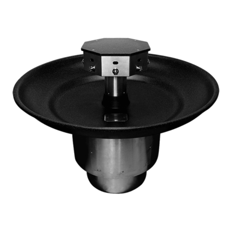
AquaFount-90®Washfountain
WAF-2200 Series
Willoughby Industries, Inc. TOLL FREE (800) 428-4065 ● LOCAL (317) 875-0830 ● FAX (317) 875-0837
Page 3www.willoughby-ind.com
INSTALLATION INSTRUCTIONS
Visit our website at http.//www.willoughby-ind.com
2210 West Morris Street • P.O. Box 21217 • Indianapolis, IN 46221
(317) 638-2381 • Fax: (317) 638-6110 • (800) 428-4065
© Rev. 11/2007 Page 3
Installation notice!
Check Rough-in location and flush lines prior to hook up!
When installing the Willoughby Industries’ WAW, WAF, or WWF series
washfountains or lavatory deck systems:
Before Step 1 of the installation instructions, ensure that rough-ins are in the correct
location.
It is essential that the water supply lines be thoroughly flushed prior to making final
connection to the hot and cold water supply lines. These lines must be flushed
sufficiently to remove the small particles of debris that are inherent with new
construction projects. If this debris is not removed, the valving in these units will be
damaged. Do not attempt to remove aerators to flush debris into the lavatory. The
damage can only be fixed by replacing the valves. Damage to valves caused by debris
will not be covered by the manufacturers warranty.
Installation notice!
Check Rough-in location and flush lines prior to hook up!
© Rev. 5/2010
When installing the Willoughby Industries' WAF-2200 Series washfountain:
Before Step 1 of the installation instructions, ensure that rough-ins are in the correct location�
The valve assembly, including the spray head, MUST NOT BE connected until after
all lines have been ushed to remove the small particles of debris that are inherent
with new construction projects and all chemicals that are used in ushing are purged
from the system�
Chemicals used in ushing plumbing systems can attack the internal components of
the valve and spray head and severely damage them, so any ushing of the system
must be followed by a full ushing with pure water to clear any harsh chemicals
remaining in the system� Debris in the system if allowed to enter the valve assembly
and spray head can cause poor performance or outright failure�
Again DO NOT attempt to connect the valve assembly and spray head until after all
ushing is complete and pure water is the only media that will be passing through the
system� Damage to the valve assembly or spray head caused by harsh chemicals or
debris will not be covered by the manufacturer's warranty�
INSTALLATION INSTRUCTIONS
Visit our website at http.//www.willoughby-ind.com
2210 West Morris Street • P.O. Box 21217 • Indianapolis, IN 46221
(317) 638-2381 • Fax: (317) 638-6110 • (800) 428-4065
© Rev. 11/2007 Page 3
Installation notice!
Check Rough-in location and flush lines prior to hook up!
When installing the Willoughby Industries’ WAW, WAF, or WWF series
washfountains or lavatory deck systems:
Before Step 1 of the installation instructions, ensure that rough-ins are in the correct
location.
It is essential that the water supply lines be thoroughly flushed prior to making final
connection to the hot and cold water supply lines. These lines must be flushed
sufficiently to remove the small particles of debris that are inherent with new
construction projects. If this debris is not removed, the valving in these units will be
damaged. Do not attempt to remove aerators to flush debris into the lavatory. The
damage can only be fixed by replacing the valves. Damage to valves caused by debris
will not be covered by the manufacturers warranty.
Installation notice!
Check Rough-in location and flush lines prior to hook up!
© Rev. 5/2010
Check Rough-In location PRIOR to installation
Flush lines thoroughly PRIOR to hook-up
Check Rough-In location PRIOR to installation
Flush lines thoroughly PRIOR to hook-up
Pre-Installation Information

