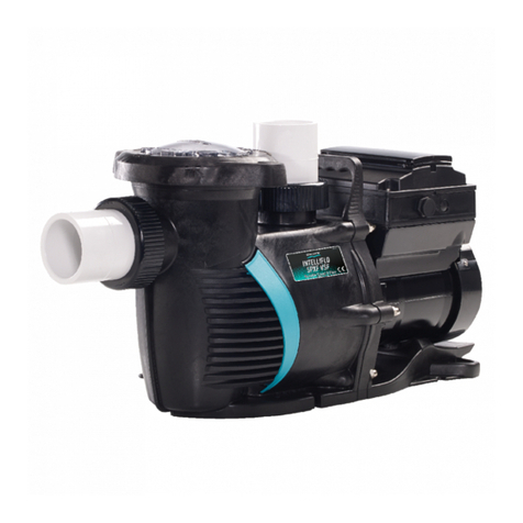
Wilo Wilo-FilTec FBS User manual

Einbau- und Betriebsanleitung
Installation and Operating Instructions
Notice de montage et de mise en service
Onderhouds- en bedieningsvoorschrift
Wilo-FilTec FBS
D
GB
F
NL
2018538/2000.09.DDD

Fig. 1 Fig. 2
Fig. 2a

Fig. 5Fig. 4
Fig. 3

Bei Sicherheit hinwei en, deren Nichtbeachtung
Gefahren für die Ma chine und deren Funktion her-
vorrufen können, i t da Wort
eingefügt.
2.2 Personalqualifikation
Da Per onal für die Montage muß die ent pre-
chende Qualifikation für die e Arbeiten aufwei en.
2.3 Gefahren bei Nichtbeachtung der
Sicherheitshinweise
Die Nichtbeachtung der Sicherheit hinwei e kann
eine Gefährdung für Per onen und Filterpumpe zur
Folge haben. Die Nichtbeachtung der Sicher-
heit hinwei e kann zum Verlu t jeglicher Scha-
dener atzan prüche führen.
Im einzelnen kann Nichtbeachtung bei piel wei e
folgende Gefährdungen nach ich ziehen:
– Ver agen wichtiger Funktionen der Pumpe/
Anlage,
– Gefährdungen von Per onen durch elektri che
und mechani che Einwirkungen.
2.4 Sicherheitshinweise für den Betreiber
Die be tehenden Vor chriften zur Unfallverhütung
ind zu beachten.
Gefährdungen durch elektri che Energie ind au -
zu chließen. Vor chriften de VDE und der ört-
lichen Energiever orgung unternehmen beachten.
2.5 Sicherheitshinweise für Inspektions- und
Montagearbeiten
Der Betreiber hat dafür zu orgen, daß alle
In pektion - und Montagearbeiten von autori ier-
tem und qualifiziertem Fachper onal au geführt
werden, da ich durch eingehende Studium der
Betrieb anleitung au reichend informiert hat.
Grund ätzlich dürfen Arbeiten an der Filterpumpe
nur im Still tand durchgeführt werden.
2.6 Eigenmächtiger Umbau und
Ersatzteilherstellung
Veränderungen der Filterpumpe ind nur nach
Ab prache mit dem Her teller zulä ig. Original-
er atzteile und vom Her teller autori ierte
Zubehör dienen der Sicherheit. Die Verwendung
anderer Teile kann die Haftung für die darau ent-
tehenden Folgen aufheben.
2.7 Unzulässige Betriebsweisen
Die Betrieb icherheit der gelieferten Filterpumpe
i t nur bei be timmung gemäßer Verwendung
ent prechend Ab chnitt 1 der Betrieb anleitung
gewährlei tet. Die im Datenblatt angegebenen
Grenzwerte dürfen auf keinen Fall über chritten
werden.
3 Transport und Zwischenlagerung
Die Filterpumpe i t von außen gegen
Feuchtigkeit zu chützen!
4 Beschreibung des Erzeugnisses
4.1 Beschreibung der Filterpumpe (Bild 1)
Da Pumpengehäu e be teht au einem gla fa er-
ver tärkten Kun t toff für den Ein atz im
Schwimmbad. Die Pumpe i t mit einem Naß-
läufermotor in Wech el- oder Dreh tromau -
führung au gerü tet und i t elb tan augend.
Vor der Pumpe i t ein Grobfilter angeordnet, der
icher tellt, daß die Pumpe nicht durch grobe
Verunreinigungen ver topft wird. Ein erienmäßiger
Wicklung chutzkontakt (WSK) bewahrt die Pum-
pe vor Be chädigung bei Überla tung. Der WSK i t
aber nur in Verbindung mit einem ent prechenden
Schaltgerät/-ka ten wirk am.
Die Pumpe augt da Schwimmbadwa er z.B.
über den Oberflächen-Ab auger (Skimmer) an und
pumpt e über den Filter gereinigt wieder in
Schwimmbecken zurück. Oberflächen-Ab auger
(Skimmer) und Filter ind bau eitig beizu tellen.
4.2 Lieferumfang
– Filterpumpe
– 2 Übergang tücke mit Überwurfmuttern und
Flachdichtungen:
für FBS 10 und 15: l50 x 40 mm,
für FBS 20 und 25: l63 x 74 mm
– vorge chalteter integrierter Vorfilter
– Filterkorb im Vorfilter
– Ring chlü el zum Lö en de Grobfilterdeckel
– Einbau- und Betrieb anleitung
5 Aufstellung/Einbau
– Typen childdaten beachten.
5.1 Montage
– Die Filterpumpe i t waagerecht einzubauen.
– Vor und hinter der Pumpe ollten Ab perr-
armaturen eingebaut werden, um einen evtl.
Pumpenau tau ch zu erleichtern. Dabei i t die
Montage o durchzuführen, daß evtl. Leckwa er
nicht auf die Pumpe tropfen kann.
– Saug- und Druckleitung au PVC mit den Über-
gang tücken der Pumpe verkleben:
für FBS 10 und 15: Rohrleitung wird in da Über-
gang tück ge teckt,
ACHTUNG!
ACHTUNG!
DEUTSCH
4

für FBS 20 und 25: Rohrleitung wird über da
Übergang tück ge choben.
– An chließend die An chlußleitungen mit der
Pumpe ver chrauben (Flachdichtungen einle-
gen).
Die Überwurfmuttern haben ein Son-
dergewinde. Keine anderen Ver-
chraubungen benutzen!
– Die An chlußrohre mü en pannung frei mit
der Pumpe verbunden ein.
5.1.1 Aufstellungshinweise
- Einbaumaße und An chlußgrößen ind der
Tabelle 2 im Ab atz 1.2.1 und Maßzeichnung zu
Tabelle 2 zu entnehmen.
– Die Pumpe kann, vom Saugan chluß geme en,
bi 5 m unter und bi 2 m über dem Wa er-
piegel aufge tellt werden (Bild 2).
– Da zweckmäßig te Auf tellung niveau i t unter-
halb der Wa eroberfläche. Die Pumpe kann
dann im Zulaufbetrieb arbeiten ( ie braucht
keine Saugarbeit zu lei ten).
– Grund ätzlich ind die Saugleitungen o kurz
wie möglich au zuführen.
– Muß die Pumpe oberhalb de Wa er piegel
aufge tellt werden, ollte die Saugleitung (vom
Becken zur Pumpe) möglich t in voller Länge
unterhalb de Wa er piegel verlegt und er t
an der Filterpumpe nach oben geführt werden,
damit die Saugleitung beim Still tand der
Filterpumpe möglich t wenig leerläuft.
– Steht die Filteranlage über dem Wa er piegel,
und die Saugleitung i t außerdem noch lang, i t
e innvoll, die Umwälzpumpe getrennt von der
Filteranlage in Beckennähe und unterhalb de
Wa er piegel aufzu tellen.
– Bei Saugbetrieb ind leichte, aber gut dichtende
Rück chlagklappen im tief ten Punkt der Saug-
leitung einzubauen. Sie helfen, den Wa er tand
im Saugrohr bei abge chalteter Filteranlage zu
halten. Die e Klappen mü en jedoch zugäng-
lich und au baubar ein, damit ie gereinigt wer-
den können.
– Maximal zulä ige Länge der ge amten Ring-
leitung beträgt 30 m.
5.2 Elektrischer Anschlu
5.2.1Sicherheitshinweise
Al wirk amer Schutz gegen Elektro-
unfälle i t der Einbau eine Fehler-
trom chutz chalter (FI-Schalter) für
die ge amte In tallation im Schwimm-
badbereich erforderlich. Au lö e trom
30 mA.
Die Zuleitung i t mit einem allpoligen Haupt chalter
(Kontaktöffnung weite min. 3 mm) zu ver ehen.
Zur Sicherung gegen zu hohe Berührung -
pannung ind alle metalli chen Teile am Boden
oder am Becken mit einer Potentialau gleich -
leitung (LPA) zu verbinden. Die e Leitung, Min-
de tquer chnitt 10 mm2Cu, ollte mit einer eigen
angelegten Potentialau gleich chiene verbunden
und die e wiederum geerdet werden, z. B. mit ei-
nem Banderder, Plattenerder o.a. Separat i t die e
Au gleich chiene mit dem vom Netz kommenden
Schutzleiter zu verbinden.
Der Erdwider tand der Potentialau gleich leitung
muß kleiner ein al 800 Ohm, damit im Fehlerfall
keine höhere Berührung pannung al 24 V auf-
tritt.
Um die Funktion de Wicklung chutzkontakte
(WSK) icherzu tellen, i t bau eit ein Schalt-
gerät/-ka ten beizu tellen (Wilo-Lieferprogramm).
5.2.2 Allgemeine Hinweise
– Der elektri che An chluß i t von einem
beim örtlichen EVU zugela enen
Elektroin tallateur und ent prechend
den geltenden VDE-Vor chriften (VDE
0100, Teil 702) au zuführen.
– Stromart und Spannung de Netzan chlu e
überprüfen
– Typen childdaten de anzu teuernden Pumpen-
motor beachten
– Netz eitige Ab icherung: 10 A, träge
– Bodenplatte (nicht im Lieferumfang enthalten) an
der dafür vorge ehenen Erdung chraube er-
den
– Schutzart IP 54
– Der Pumpenmotor i t mit einem Wicklung -
chutzkontakt (WSK) au gerü tet. Im Schalt-
gerät/-ka ten der Filteranlage muß eine ent pre-
chende An chlußmöglichkeit vorhanden ein.
5.2.3 Klemmenleisten
Elektri chen An chluß ent prechend den
Klemmenan chlußbildern au führen.
Bild 3: Motorklemmenbrett für EM 1 Ù230 V
Bild 4: Motorklemmenbrett für DM 3 Ù230 V (V)
Bild 5: Motorklemmenbrett für DM 3 Ù400V (Y)
6 Inbetriebnahme
– Schwimmbecken und, fall vorhanden, Schwall-
wa erbehälter mü en gefüllt ein.
– Alle Ab perrarmaturen chließen.
ACHTUNG!
DEUTSCH
5
– Überwurfmutter (Bild 1, Po .3) de Grobfilter-
behälter (Bild1, Po .2).mit dem mitgelieferten
Ring chlü el lö en und Filterdeckel (Bild 1,
Po .4) abnehmen.
Bei jeder Inbetriebnahme nach einer
Entleerung de Sy tem Grobfilter-
behälter mit Wa er füllen! Im Falle
der Auf tellung der Filteranlage ober-
halb de Wa er piegel wird damit
die Selb tan augfähigkeit der Pumpe
icherge tellt.
– Deckel mit der dazu vorge ehenen O-Ring-
Dichtung wieder auflegen und Überwurfmutter
mit dem Schlü el handfe t anziehen.
Pumpe nie ohne Grobfilter (Bild 1,
Po .9) in Betrieb nehmen!
– Ab perrarmaturen wieder öffnen.
– Pumpe bzw. Schaltgerät ein chalten
– Drehrichtung kontrolle: nur bei Dreh trommotor
erforderlich. Pumpe kurz ein chalten. Die auf
dem Klemmenka ten (Bild 1, Po .6) de Motor
ichtbare Leuchtanzeige darf nicht brennen.
Leuchtet ie, o läuft der Motor in fal cher
Drehrichtung. Zwei beliebige Pha en de Netz-
an chlu e vertau chen.
– I t im Steuergerät eine elektroni che Ab-
icherung gegen Motorüberla tung eingebaut,
o muß da Gerät auf den Nenn trom de Motor
einge tellt werden.
– Kurzzeitiger Trockenlauf chadet der Pumpe
nicht. Sie ollte aber nicht längere Zeit ohne
Wa er laufen.
– Die weiteren Inbetriebnahme-Schritte ind der
Einbau- und Betrieb anleitung der Filteranlage
zu entnehmen.
7 Wartung / Instandhaltung
– Bei nicht fro t icher aufge tellten Filteranlagen
z.B. für Freibäder muß auch die Filterpumpe im
Winter entleert werden. Dazu ind die
Entleerung chrauben an der Pumpe (Bild 1,
Po .7) mit einem geeigneten Werkzeug zu öff-
nen. Die PVC-Schrauben können leicht be chä-
digt werden. Entleerung chrauben nur hand-
fe t anziehen.
– Der Grobfilter i t von Zeit zu Zeit zu kontrollieren
und zu reinigen. Dabei die O-Ring-Dichtung und
deren Sitzfläche auber halten (Bild 1, Po .5).
Den Grobfilter wieder o ein etzen, daß die vor-
handene Au parung im Ein atzrand in die Na e
der Sitzfläche de Gehäu e greift. (Ab chnitt 6
Inbetriebnahme beachten!)
– Bei einem Pumpendefekt: Pumpe zuer t ab-
chalten, dann kann der Motorblock (Bild1,
Po .1) vom Pumpengehäu e durch Lö en der
acht Schrauben (Bild 1, Po .10) getrennt werden.
Bei der Wiedermontage i t auf korrekten Sitz der
beiden O-Ring-Dichtungen (Bild 1, Po .8) zu
achten. Schrauben über Kreuz gleichmäßig an-
ziehen. Der Motorblock darf nur von qualifizier-
tem Per onal demontiert und montiert werden.
Zur Aufrechterhaltung von Garantie-
an prüchen dürfen Reparaturarbei-
ten nur durch den Kundendien t de
Her teller au geführt werden.
ACHTUNG!
ACHTUNG!
ACHTUNG!
DEUTSCH
6

DEUTSCH
7
8 Störungen, Ursachen und Beseitigung
Störung Ursache Beseitigung
Pumpe füllt ich nicht Lufteintritt am An augrohr Zu tand der An chlü e, Verbindungen und
Dichtungen überprüfen
Grobfilterdeckel Grobfilterdeckel reinigen und Zu tand der O-
chließt nicht dicht Ring-Dichtung prüfen
Fal che Drehrichtung de 2 Pha en de Netzan chlu e vertau chen
Motor (DM-Au führung)
Pumpe fördert zu Lufteintritt am An augrohr Zu tand der An chlü e, Verbindungen und
wenig Wa er Dichtungen überprüfen
Fal che Drehrichtung de 2 Pha en de Netzan chlu e vertau chen
Motor (DM-Au führung)
Druckverlu t beim An augen Elemente, die Druckverlu te verur achen,
vermeiden
Fal che Spannung Prüfen, ob Netz pannung mit der auf dem
Typen child überein timmt.
Grobfilter ver topft Grobfilter reinigen
Hauptfilter ver topft Rück pülvorgang einleiten
Au fall de Motor Pha enau fall Bei Rückkehr der Spannung tellt ich
vorheriger Betrieb zu and wieder ein.
WSK de Pumpenmotor Motor abkühlen la en, Störung am Schalt-
hat au gelö t gerät/-ka ten quittieren, Pumpe läuft wieder
an. Bei wiederholtem Au lö en de WSK muß
die Pumpe elektri ch und mechani ch über-
prüft werden.
Falls die Störung bzw. der Fehler nicht behoben werden kann, wenden Sie sich bitte an den Wilo-
Kundendienst.
Technische Änderungen vorbehalten!

1 General
Installation and service by qualified personnel
only!
1.1 Applications
The pool circulating pump are u ed in conjunc-
tion with highrate and filter plant for private
wimming pool . They are re i tant to chemical
normally u ed for pool maintenance, but not to ea
or alt water.
ENGLISH
8
1.2 Technical data
1.2.1Performance and electrical data (Table 1)
Max. permi ible pre ure 2,3 bar
Main voltage 1 Ù230 V ± 10 % , 50 Hz
3 Ù400 V ± 10 % , 50 Hz
Speed ee rating plate
Capacity and current ee rating plate
Flow rate and -heat ee rating plate
Protective y tem IP 54
Haupt- und An chlußmaße, Tabelle 2
Type dimen ion [mm]
FBS DA DI h l1 l2
10 – 50 366 265 525
15 – 50 366 265 560
20 and 25 63 – 400 300 595
Re i tance to chemical are limited by the follo-
wing limit :
– Max. water temperature: 40°C
– pH-value: min. 6, max. 7,8
– Free chlorine: 0.2 up to max. 2.0 mg/l (or ppm),
Short term limit e.g. for reconditioning of pool
water max. 20 ppm.
– Free chloride : max. 250 mg/l
– The pump i not uitable to handle ea or alt
water
– Pump mu t not be u ed to handle water condi-
tioned by Sodium Hypochlorit (by electroly i ).
– Pump mu t not run dry.
2 Safety Notes
The e in truction contain ba ic reference which
mu t be trictly adhered to. It i therefore impera-
tive for the in taller and the Operator to carefully
read the e in truction prior to in tallation and
commi ioning.
Plea e ob erve, not only the afty direction under
the main heading SAFTY RULES, but al o tho e
added and pecially marked under the en uing he-
ader .
2.1 Safty marks contained in these instructions
Safaty reference contained here in which, if not
complied with, may cau e death or evere per o-
nal injury from electrical cau e are pecially high-
lighted by the following danger ymbol:
Safty refernce which, if not complied with, may re-
ult in damage to the plant or it function are high-
lighted by the word:
ATTENTION!

2.2 Trade qualifications
Only qualified per onnel may work on thi equip-
ment.
2.3 Dangers from non- oberservance of safety
references
Non- ober ervance of afety reference may cau e
bodily harm to per on or damage to the filter
pump. Failure to comply with afety reference
could invalidate warranty and/or damage claim . In
detail, non-compliance may, for example, cau e
the following dangerou po ibilitie :
– failure of vital plant function or damage to plant,
– cau ing per onal injury due to electrical and/or
mechanical cau e .
2.4 Safety refernce for the Operator
It i the Operator´ re pon ibility to en ure that in-
pection and in tallation work are carried out by
authorized and qualified per onnel only, having
them elve made fully conver ant with the e in-
truction .
Work mu t principally be carried out only with the
plant witched off and at complete tand till.
2.5 Safety reference for inspections
and installation work
It i the Operator´ re pon ibility to en ure that in-
pection and in tallation work are carried out by
authorized and qualified per onnel only, having
them elve made fully conver ant with the e in-
truction .
Work mu t principally be carried out only with the
plant witched off and at complete tand till.
2.6 Arbitrary alterations and spare
part procurement
Any alteration to the plant are only permitted in
agreement with the manufacturer . Original pare
part and authorized acce orie erve afety and
reliability. The u e of unauthorized part could in-
validate any claim for con equential damage .
2.7 Abnormal operating conditions
Operational afety of the plant i only en ured if
u ed in accordance with chapter 1 of the e in-
truction . The limit tated there mu t not be ex-
ceeded under any circum tance .
3 Transport and Storage
The filter pump mu t be externally
protected from moi ture.
4 Description of Product and
Accessories
4.1 Description of the pool circulating pump
(Fig. 1)
The pump hou ing i con tructed of gla fibre rein-
forced pla tic for u e in wimming pool . The
pump i of the canned- rotor type, elf-priming and
optionally available with ingle or three pha e mo-
tor . The inlet port i equipped with a lint trainer in
order to prevent coar e impuritie entering and
jamming the pump. Standard thermal overload
contact (WKS) prevent damage to the pump due
to exce current draw. The WSK i , however, only
effective in conjunction with an appropiate witch-
box.
The pump draw water from the pool, e.g. via a
kimmer and pump it back to the pool via the fil-
ter.
4.2 Scope of supply
– Pool circulating pump
– Two (2) connector with union nut , in ert and
wa her
Size FBS 10 and 15: 50 diam.x40 mm,
Size FBS 20 and 25: 63 diam.x74mm
– connected integrated preliminary filter
– filter cartridge in the preliminary filter
– Ring panner for handling the coar e trainer
cover
– In tallation and Operating In truction .
5 Siting/Installation
– ob erve data on the motor rating plate
5.1 Installation
– In tall the pool circulating pump with the haft in
the hotizontal plane
– Glue PVC uction and di harge pipe to pump
union connection
Size FBS 10 and 15:Pipe to be pu hed into the
in ide of the union in ert
Size FBS 20 and 25:Pipe to be pu hed onto the
out ide of the union in ert
– Screw connecting pipe onto the pump after in-
erting the wa her
The union nut have pecial thread .
Do not u e any other kind of union
nut .
– Connection to the pump to be done uch that it
i not tre ed by the pipework.
ATTENTION!
ATTENTION!
ENGLISH
9

5.1.1 Mounting instructions
– Dimen ion for in tallation and conection are
given in table 2 paragragh 1.2.1 and fig. 2a
– The pump can be mounted up to 5 metre below
and up to 2 metre above pool water level, mea-
ured from uction inlet connection (Fig.2).
– The mo t uitable mounting level i below the
pool water level. The pump then operate under
flooded uction (without uction lift).
– On priciple, uction line hould be a hort a
po ible.
– If it i nece ary to mount the pump above pool
water level, the uction pipe (from pool to the
pump) hould preferably be run full-length hori-
zontally below water level and only ri e directly
at the pump. The uction line will then, on hut-
down of filter pump, only lightly be emptied.
– If the and filter i placed above water level and
with an additionally long uction run, the circula-
ting pump hould preferably be mounted epe-
rate from the filter clo e to the pool below water
level.
– When operating with a uction lift, light-weight
but po itively ealing non-return valve hould be
fitted at the lowe t point of the uction line. They
will a i t in maintaining the water level in the
uction line during tand till of the filter plant.
The e checkvalve mu t, for the ea e of clea-
ning, be ea ily acce ible and removable.
– Total length of the circulating pipework mu t not
exceed 30 metre .
5.2 Electrical wiring
5.2.1 Safety information
A an effective protection again t di a -
trou effect of earth fault current it i
required to in tall an earth fault circuit
interruptor (Fl- witch) for the total elec-
trical circutery of the pool y tem. Trip
current 30mA.
An all-pole i olation witch (min.contact gap 3mm)
mu t be in talled in the power upply cable.
A an protection from exce ively high hock vol-
tage it i required to connect all metallic part at
pool bottom and wall with a potential compen a-
tion wiring. Thi copper wire, minimum ize 10 mm2
CU, hould be conncted to a pecially et and ear-
thed potential compen ating bu bar, which i to be
eperately connected to the earth wire of the power
upply.
The earthing re i tance of the potential compen a-
ting wire mu t be le than 800 ohm in order to
re trict the hock voltage to le than 24 V in ca e
of a fault.
A witchbox mu t be provided on ite by other to
en ure the thermall overload contact (WSK) of the
pump motor to be effective.
5.2.2 General information
– Electrical work to be carried out by
qualified and licen ed electrician in
trict conformity to ruling national tan-
dard and local regulation ..
– Check available power upply data
– Ob erve pump name plate data
– Power upply fu e : 10A, inert action
– Ba eplate (on ite by other ) to be earthed
– Degree of protection: IP 54
– The pump motor i internally equipped with ther-
mal overload contact (WSK). En ure that re-
pective terminal are available in the filter witch-
box.
5.2.3 Terminals
Effect on- ite wiring according to the wiring dia-
gram :
Fig. 3: Motor terminal block for ingle pha e-
230/240V
Fig. 4: Motor terminal block for three pha e- 230V
(V)
Fig. 5: Motor terminal block for three pha e-
400/415V (Y)
6 Commissioning (Fig.1)
– Pool and balance tank (if applicable) mu t be fil-
led
– Clo e all in olating valve
– Undo cover nut (Item 3) of the lint trainer (Item
2) with the aid of the ring panner provided and
remove trainer cover (Item 4).
Lint trainer mu t be filled with after
draining the pipe y tem. Thi en-
ure priming ability of the pump in
ca e of filter plant in tallation above
pool water level.
– Repo ition of lint trainer cover and ecure by
tightening with the ring panner.
Pump mu t never be run without the
lint trainer (Item 9)!
– Open i olating valve .
– Switch on pump or witchbox re pectively.
– Direction of rotation check: Only required in the
ca e of three pha e motor . Briefly witch-on
pump. The pilot light on the terminal box (Item 6)
mu t be off. If it i on, the pump rotate in the
ATTENTION!
ATTENTION!
ENGLISH
10

wrong direction. Then, change any two pha e
wire of the power upply.
– If u ing witchgear with integral electronic over-
load control, it mu t be adju ted to the full load
current value of the motor.
– Short- term dry- running doe not damage the
pump; prolonged dry- running mu t, however, be
avoided.
– Further tep on plant commi ioning in accor-
dance with the Operating In truction of the
and filter plant.
7 Maintenance (Fig. 1)
– If not located in a fro t- free location (e.g. open-
air pool ), en ure that circulating pump are
drained during winter together with the filter
plant. Thi i done by undoing the drain plug at
the pump (Item 7) with the aid of a uitable tool.
The PVC crew are prone to damage. Drain
plug to be fa tened hand-tight only.
– The lint trainer mu t be checked and cleaned
from time to time. The O-ring ga ket and it eat
mu t be kept clean (Item 5). The filter ba ket
mu t be repo itioned uch that the groove at the
top ring fit the locating knob in the eating of the
trainer hou ing (ob eve Chapter 6, Commi -
ioning).
– In the ca e of a pump failure, fir t witch-off the
motor; the tator hou ing (Item 1) can then be e-
parated from the pump hou ing by undoing and
removing the eight (8) holding -down crew
(Item 10). When re-a embling, en ure correct
eating of the two (2) O-ring wa her (Item 8).
Screw to be tightened cro - wi e. Removal
and re- a embly of the tator hou ing mu t only
be done by qualified per onnel.
In order to maintain warranty claim ,
repair mu t only be effected by
WILO- authorized ervice.
ATTENTION!
ENGLISH
11

ENGLISH
12
8 Fault finding- Causes and Remedies
If the faults cannot be located and rectified, please contact your nearest Wilo representative.
Technical modifications reserved!
Fault Cause Remedy
Pump doe not fill Air entry in uction pipe Check condition of pipe, connection ,
and eal .
Cover of lint trainer doe Clean trainer cover and check condition
not eal tight of O-ring wa her.
Wrong direction of motor Change any two pha e wire .
rotation (3-pha e motor)
In ufficient pump Air entry in uction pipe Check condition of pipe , connection ,
performance and eal .
Wrong direction of motor Change any two pha e wire .
rotation (3-pha e motor)
Pre ure lo in uction Eliminate any element cau ing exce ive
pipe re i tance.
Wrong voltage Check that available voltage corre pond
with name plate data.
Chocked lint trainer Clean lint trainer
Chocked main and filter Start backwa h cycle.
Motor failure Lo of pha e The original operating condition are
automatically re tored on power re toration.
WSK of pump motor ha Let motor cool down, re et fault at witchbox,
tripped pump will re tart. On repeated tripping of the
WSK it will be nece ary to check pump
electrically and mechanically.
Table of contents
Languages:
Popular Swimming Pool Pump manuals by other brands

mundoclima
mundoclima MUPIR-H9 user manual

Astral Pool
Astral Pool Viron P320 eVo Original instructions

Gardena
Gardena WP 700 S 7851 operating instructions

Intex
Intex ECO15220-1 owner's manual

Espa
Espa TIFON1 instruction manual

Pentair Pool Products
Pentair Pool Products Challenger Installation, operation & service manual