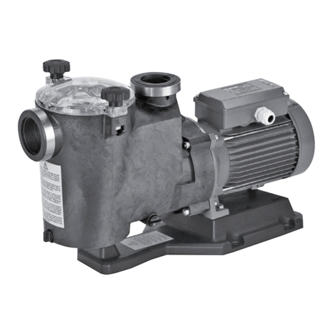
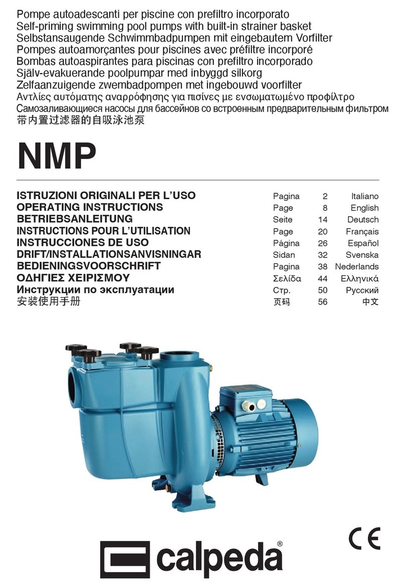
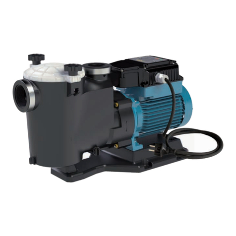
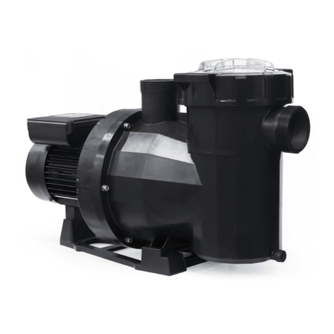
Calpeda MPC Compact Pool User manual

Self-priming swimming pool pumps
with built-in strainer
MPC
Compact Pool
OPERATING INSTRUCTIONS
1. Operating conditions
Standard construction
- For water circulation in swimming pool filtration
systems.
- For clean or slightly dirty water with solids in
suspension, with a maximum temperature of
60 °C.
- Maximum permissible hydrostatic pressure and
pump discharge pressure: 2.5 bar.
- Maximum ambient temperature: 40 °C.
- Maximum starts/hour: 10 at regular intervals.
Sound pressure: < 70 dB (A). MPC7: 72 dB (A).
To isolate the motor from pumped water, the MPC
Compact Pool pumps are made with high quality
plastic materials. Necessary precaution during
installation along with use in accordance with
the limits specified will ensure trouble-free
operation.
2. Installation
The MPC Compact Pool pumps must be
installed in well ventilated locations protected
from the weather, with the rotor axis horizontal
and feet downwards.
Place the pump as close as practicable to the
suction source.
To reduce the risk of electric shock
install the pump at least 3 m from the
inside walls of a swimming pool. For use
as a portable pump in outdoor locations
provide suitable protection and mount the pump
on an insulating base of at least 100 mm height.
Follow section 4.
Provide space around the unit for motor
ventilation, easier inspection, removal of the
strainer basket, filling and draining the pump and
checking (with a screwdriver) for free rotation of the
shaft (fig. 1). With three-phase motors a sight
check of the direction of shaft rotation will be
required.
3. Pipes
Provide a diameter assuring a liquid flow not greater
than 1.5 m/s for suction and 3 m/s for delivery.
The pipe diameters must never be smaller than
the pump connection ports.
ATTENTION: ensure the inside of pipes are
clean and unobstructed before connection.
Aconcentrated sand content with particles
larger than the radial clearance between the
impeller and the stainless steel wear-ring (about
1 mm) can cause early wear damage and a
reduction of the pump performance of about 10%.
For a hydrostatic pressure test of the piping with
a pressure higher than 2.5 bar isolate the pump
from the rest of the system (close inlet and outlet
valves before and after the pump).
3.1. Connecting the pipes
Use pipes or fittings in plastic material.
For connection to the threaded ports of the pump
casing use a plastic pipe thread sealant (for
instance: Loctite 5331).
Teflon tape not recommended. Do not use hemp.
ATTENTION: avoid excessive tightening of
pipes or fittings in threaded ports.
Tighten the pipes or fittings only to the degree
required to ensure a tight seal.
Excessive torque may cause damage to the
pump.
To join metal piping, first connect a transition
union with a plastic tailpiece to the threaded
port of the pump casing. Coupling dissimilar
materials may cause corrosion and cracks
due to non-uniform expansion and contraction
in thermal cycling applications.
Secure all pipes to supports and connect them
so that they do not transmit stress, strain or
vibration to the pump. The pump must not be
subject to the weight or thermal expansion of
the piping.
Strain from the piping may damage or warp
the pump casing and cause leakage.
Fig. 1 Minimum access for servicing (mm)
Removing
strainer Dismantling motor
Checking
shaft
rotation
Draining Motor ventilation
Filling
8

3.2. Suction pipe
The suction pipe must be perfectly airtight.
With a pump located below water level (inflow
under positive suction head) (section 10.,fig. 7),
install inlet and outlet valves to isolate the pump.
With a pump located permanently above the
water level (suction lift operation), with various
suction pipes (for skimmers, main drain, fitting for
vacuum cleaner), connect all the pipes with their
own gate valve to a manifold. As far as possible,
locate the pipes and the manifold below water level
with the pump being reached by a single vertical
pipe (see section 11., figure 8b and section 5.3.).
With a pump located permanently above the water
level of a swimming pool, avoid suction lifts higher
than 3 m with respect to the main drain. With a
suction lift above 1,5 m fit a check valve
(accessible) in the suction line from the main drain.
In operating with flexible hoses, use a reinforced
spiral suction hose in order to avoid hose
narrowing due to suction vacuum.
4. Electrical connection
Electrical connection must be carried
out only by a qualified electrician in
accordance with local regulations.
Follow all safety standards.
The unit must be properly earthed (grounded).
Connect the earthing (grounding) conductor to
the terminal with the marking.
Compare the frequency and mains voltage with
the name-plate data and connect the supply
conductors to the terminals in accordance with the
appropriate diagram inside the terminal box cover.
ATTENTION: never allow washers or other
metal parts to fall into the internal cable
opening between the terminal box and stator.
If this occurs, dismantle the motor to recover
the object which has fallen inside.
If the terminal box is provided with and inlet
gland, use a flexible power supply cord of the
H07 RN-F type. If the terminal box is provided
with an inlet bushing, connect the power supply
cord through a conduit.
For use in swimming pools, garden ponds and
similar places, a residual current device with
IΔN not exceeding 30 mA must be installed in the
supply circuit.
Install a device for disconnection from the
mains (switch) with a contact separation of at
least 3 mm on all poles.
With a three-phase motor install an overload
protection device appropriate for the rated current
of the pump.
Single-phase MPCM Compact Pool pumps are
supplied with a capacitor connected to the
terminals and (for 220-240 V - 50 Hz) with an
incorporated thermal protector.
5.
1.
Starting
5.1. Checking the direction of rotation
ATTENTION: when the pump is started for the
first time, with three-phase motors check the
direction of rotation.
With the three-phase models MPC 5, 6, 7,
check the direction of rotation before filling the
pump (see also section 8.).
First check that the shaft turns by hand.
For this purpose use the screwdriver notch on the
shaft end at the motor fan side. Turn the shaft by
hand only in the direction indicated by the arrows
on the pump casing.
Do not start the motor if the shaft is jammed.
If jammed, the impeller may unscrew should
the motor start rotating backwards. Reverse
rotation can also damage the mechanical seal.
Momentarily start the motor to check rotation of
the pump shaft, which must be as shown by the
arrows on the pump casing: clockwise when
viewing the shaft from the motor end. Otherwise,
disconnect electrical power and reverse the
connections of two phases.
5.2. Filling
ATTENTION: avoid running dry.
When operating with the pump below water
level (inflow under positive suction head), fill the
pump by opening the suction gate valve slowly
and completely, keeping the delivery gate valve
open to release the air.
When the pump is located above the water
level (suction lift operation) fill the pump with
water up to suction port level through the opening
on the strainer after removing the cover (fig. 2).
Fig. 2 Filling
9
After starting, check that the pump works within
its field of performance and that the absorbed
current shown on the name-plate is not exceeded;
otherwise adjust the delivery gate valve.
Avoid long operation with a closed valve.
5.3. Self-priming
(Capability to clear the air in the suction pipe
when starting with the pump located above the
water level and when the suction pipe cannot be
filled manually, as in the case of a missing foot
valve).
Maximum suction lifts and minimum self-priming
times (see the data sheet) are reached with a
standard electric motor (n = 2900 rpm), air-free
water with a temperature below 25 °C and a
single suction pipe with inlet diameter equal to
that of the suction connection of the pump.
Conditions for self-priming:
• Pump casing filled with water up to suction port
level before starting.
Note that with suction lift above 1,5-2 m
(without a foot valve or a check valve into
the suction pipe) the filling operation must
be repeated before each start-up.
•Suction and discharge valves completely
opened and pipes not obstructed.
• Strainer basket not obstructed.
• Suction pipe with connections perfectly airtight,
and properly immersed in the water to be lifted.
• O-ring on the strainer casing and mechanical
seal perfectly airtight (properly seated, clean
and not damaged).
• Hand wheels on strainer cover and thumbscrew
drain plug on strainer casing tightened to
prevent air entering.
•Discharge pipe without check valve, with
minimum 80 cm straight vertical free pipe above
discharge port. With suction lift below 2 m
vertical section on the pump can be 50 cm. With
suction lift lower than 1 m, an elbow can be
mounted directly onto the delivery port without a
vertical section of piping.
On expiry of the foreseen times, make sure
(through the transparent strainer cover) pump
priming has taken place and that water is flowing
regularly.
If the pump does not prime, check all
conditions above and remedy where necessary.
Repeat the priming operation again after the
pump has been completely filled with cold water.
Avoid long operation with an unprimed pump
or with a suction pipe not immersed in the
water i.e. if water level of the pool falls too low.
By lowering the water to a level below the
skimmers and other suction ports (for emptying of
the pool), keep open only the gate valve in the
pipe for suction from the bottom (main drain).
6. Maintenance
The motors with supply current directly
switched by thermally sensitive switches can
start automatically.
Disconnect electrical power before
any servicing operation and make
sure the pump cannot be accidentally
switched on.
Inspect and clean the strainer basket
periodically. The frequency of cleaning depends
on operation time of the pump, pool environment,
wind (for open air swimming pools) and the
number and behaviour of the bathers.
With the pump located below water level,
close the suction and delivery gate valves before
removing the cover.
The strainer can be easily accessed by removing
the strainer cover (fig. 3).
ATTENTION: do not use oil to lubricate the
O-ring seal. Use only water and neutral soap
to clean the transparent strainer cover. Do
not use solvents.
After cleaning, put the strainer basket in its
proper position. Fill with water up to suction port
level (see section 5.2.).
Position the strainer cover properly with the O-
ring seal on the casing and tighten the
handwheels uniformly.
Disinfectant or chemical products for
water treatment must not be poured
directly into the pump.
Risk of reactions and emission of
harmful fumes. Risk of corrosion in stagnant
water conditions (also with an increase in
temperature and decrease of pH value).
If the event of prolonged standstill periods or
if freezing may be expected, drain the pump
completely by removing the two thumbscrew
drain plugs with reusable O-ring gaskets (fig. 4).
Fig. 3 Removing and cleaning the strainer
10

Tighten drain plugs by hand. Do not use
pliers or other tools.
If necessary, use pliers only to unscrew.
Excessive torque may cause damage.
ATTENTION: after a long idle period, before
restarting the unit, fill the pump casing with
water and check with a screwdriver that the
shaft is not jammed.
If the shaft is jammed, dismantle the motor and
remove the cause.
7. Dismantling
Drain the pump casing before dismantling (see
fig. 4 and section 10.). For dismantling and
reassembly see construction in the cross-section
drawing (section 12.).
Remove the motor assembly with the lantern
bracket (32.00) from the pump casing (14.00), after
removing the screws (14.24), the nuts (14.28) and
the washers (14.29), levering them out with two
screwdrivers in diametrically opposed positions.
To remove the impeller (28.00) insert a large
straight-blade screwdriver in the slot on the shaft
(78.00) at the ventilation end.
Grip the impeller with one hand and unscrew it,
turning the shaft counter-clockwise and twisting
with both hands (fig. 5a).
If it is not possible to hold or move the shaft with
the screwdriver, remove the fan cover (90.00)
and motor fan (88.00) and unscrew the impeller
by gripping the shaft with a suitable wrench.
With the impeller the rotating part of the
mechanical seal (36.00) will be removed.
8. Assembling
To replace to mechanical seal (36.00) place the
rotating part of the seal on the impeller hub (28.00)
and push the spring right down as far as the front
shoulder. In this way, correct spring compression
will be ensured in subsequent assembly.
Lubricate the seal with water and align the
impeller on the motor shaft.
ATTENTION: with the three-phase models, to
avoid the unscrewing (and breaking) of the
impeller should the motor start rotating
backwards, clean the threaded shaft end and
apply on the first half of the threaded part
Loctite 243.
If this type of product is not used, check the
direction of rotation before filling the pump (to
avoid unscrewing due to the resistant-force of the
water in the case of a backward rotation).
Grip the impeller with one hand and turn the shaft with
a screwdriver in the clockwise direction until tight.
With this operation the front surfaces of the
mechanical seal come into contact without rubbing
against each other during tightening (fig. 5b). Clean
the O-ring (14.20) and seal surfaces with water.
When replacing the motor assembly with the
impeller be careful to insert the locating lug
inside the pump casing (14.00) into the locating
slot on the diffuser cover (27.00) (fig. 6).
ATTENTION: to avoid leakage or failure due to
misalignment and localized overstressing, the
screws (14.24) with the nuts (14.28) must be
uniformly tightened with alternated crossover
tightening in diametrically opposed positions.
Tightening torque for screws (14.24): 7 Nm.
9. Spare parts
When ordering spare parts, please quote the data
stamped on the name-plate, the part designation
and the position number of each spare part
required (in accordance with the cross-section
drawing on section 12.).
Any pumps that require
inspection/repair must be drained
and carefully cleaned inside and
outside before dispatch/submission.
Changes reserved.
Fig. 4 Draining
Air inlet
Fig. 5 Dismantling (a) and remounting (b) the impeller
4.93.149
MPC
1, 2, 3, 4 MPC
5, 6, 7
14.00 14.20 32.00
27.00
14.00
27.00
Fig. 6 Locating lug/slot for assembling pump casing
(14.00) - diffuser cover (27.00).
11

3.93.235
36
10. Pompa sotto il livello dell’acqua
Pump located below the water level
Pumpe unter dem Wasserspiegel
Pompe installée sous le niveau de l’eau
Bomba por debajo del nivel del agua
Pump under vätskenivån
Pomp onder het waterniveau
Fig. 7

37
Italiano
ATTENZIONE: questa pompa non è som-
mergibile.
Con la pompa sotto il livello dell’acqua,
prima dello smontaggio del coperchio filtro
chiudere le saracinesche in aspirazione e
mandata.
Prima di smontaggi per interventi di manuten-
zione all’impianto abbassare sotto la bocca di
aspirazione della pompa il livello dell’acqua
nella vasca.
Prima di riempire la vasca accertarsi della
chiusura dei tappi di scarico e del coperchio
filtro sulla pompa.
English
ATTENTION: this pump is not submersible.
With the pump located below the water le-
vel, close the suction and delivery gate valves
before removing the strainer cover.
Lower the water level in the swimming pool
below the suction port of the pump before di-
sassembling for servicing operations.
Make sure the thumbscrew drain plugs and
the strainer cover are properly seated and ti-
ghtened before filling the swimming pool.
Deutsch
ACHTUNG! Diese Pumpe ist keine Un-
terwasserpumpe.
Bei Anordnung der Pumpe unterhalb des
Wasserspiegels sind vor Demontage des Fil-
terdeckels die Absperrorgane vor und hinter
dem Aggregat zu schließen.
Der Wasserstand ist auf ein Niveau unterhalb
des Saugstutzens der Pumpe abzusenken
bevor eine evtl. Demontage für Wartungsar-
beiten an der Anlage beginnt.
Vor Wiederbefüllung des Swimmingspools ist
sicherzustellen, daß Entleerungsstopfen und
Filterdeckel korrekt und dicht montiert sind.
Français
ATTENTION: cette pompe n’est pas sub-
mersible.
Avec la pompe installée sous le niveau de
l’eau, avant le démontage du couvercle du
préfiltre, fermer toutes les vannes d’aspiration
et de refoulement.
Avant tout démontage pour les operations
d’entretien dans le local technique, baisser le
niveau de l’eau de la piscine sous l’orifice d’a-
spiration de la pompe.
Avant de remplir la piscine, s’assurer que le
couvercle du préfiltre est bien bloqué ainsi que
le bouchon de vidange du corps de pompe.
Español
ATENCIÒN: Esta bomba no es sumergible.
Con la bomba por debajo del nivel de
agua, antes de desmontar la tapa del filtro,
cerrar las válvulas de compuerta de la aspira-
ción y de la impulsión.
Para realizar el mantenimiento de la instala-
ción, antes de desmontar, bajar el nivel del
agua en el tanque por debajo de la boca de
aspiración de la bomba.
Antes de volver a llenar el tanque, asegurarse
de cerrar los tapones de descarga y la tapa
del filtro.
Svenska
VARNING: Denna pumptypen är ej dränkbar.
När pumpen befinner sig under vätskenivån,
stäng sug- samt tryckledningens ventiler innan
avlägsning av locket till silkorgen sker.
Sänk vatten nivån i badpoolen under sugan-
slutningen till pumpen före isärtagning för ser-
viceingrepp i anläggningen.
Se till att turnskruvarna på dräneringspluggar-
na samt sillkorgens lock är tillräckligt tätade
och åtdragna före uppfyllnad av poolen.
Nederlands
ATTENTIE: Deze pomp is geen dompelpomp.
Wanneer de pomp beneden de waterspiegel
geplaatst is moeten de afsluiters in zowel de
pers- als ook in de zuigleiding gesloten worden
voordat het filterdeksel verwijderd wordt.
Laat het waterniveau in het zwembad dalen
tot onder het niveau van de zuigaansluiting
van de pomp voordat de pomp gedemonteerd
wordt in geval van servicewerkzaamheden
aan de installatie.
Voordat het zwembad weer gevuld wordt die-
nen de aftappluggen en het filterdeksel kor-
rekt en waterdicht gemonteerd te zijn.
:
.
,
.
.
.
,
.

38
Fig. 8b
(1) Collettore Soluzione da preferire
Manifold Preferred solution
Sammelrohr Bevorzugte Lösung
Collecteur Solution préféré
Colector Solucion preferente
Rörkoppel Föredragen installation
Verzamelleiding Aanbevolen oplossing
Fig. 8a
11. Pompa sopra il livello dell’acqua
Pump located above the water level
Pumpe über dem Wasserspiegel
Pompe au dessus du niveau de l’eau
Bomba sobre el nivel del agua
Pump placerad ovanför vätskenivån
Pomp boven het waterniveau

39
Italiano
Con più tubi aspiranti (per skimmers, scarico
di fondo, attacco per pulitore del fondo), per
quanto possibile disporre i tubi ed il collettore
sotto il livello dell’acqua e raggiungere la pom-
pa con un solo tubo verticale (figura 8b).
Riducendo la lunghezza (il volume) di tuba-
zione aspirante da riempire d’acqua con la
pompa si riduce il tempo di autoadescamento
(vedere capitolo 5.3.).
English
With various suction pipes (for skimmers,
main drain, fitting for vacuum cleaner), as far
as possible, locate the pipes and the manifold
below water level with the pump being rea-
ched by a single vertical pipe (figure 8b).
By reducing the length (volume) of the suction
pipe to be filled with water by the pump, you
will reduce the priming time (see section
5.3.).
Deutsch
Mit mehreren Saugrohren (für Skimmer, Bo-
denablauf, Steckkupplung für Bodenabsaug-
gerät), die Saugleitungen und das Sammel-
rohr möglichst unterhalb des Wasserspiegels
zur Pumpe heranführen und die Pumpe nur
durch ein vertikales Saugrohr erreichen
(Abb. 8b).
Wird die Länge (das Volumen) der Sauglei-
tung, die durch die Pumpe gefüllt werden
muß, oberhalb des Wasserspiegels so kurz
wie möglich gehalten, wird die Ansaugezeit
reduziert (Siehe Kapitel 5.3.).
Français
Avec différents tuyaux d’aspiration (pour
skimmers, bonde de fond, raccord pour aspi-
rateur balai) autant que possible, placer les
tuyaux et le collecteur sous le niveau de l’eau,
jusqu’à atteindre la pompe avec un seul
tuyau vertical (figure 8b).
En réduisant la longueur (le volume) de la
conduite d’aspiration qui doit être remplie
d’eau avec la pompe le temps d’autoamorça-
ge se reduit (voir le chapitre 5.3.).
Español
Con más tubos de aspiración (para skimers,
vaciado del fondo, conexión limpia fondos),
para cuando es posible disponer los tubos y
el colector debajo el nivel del agua, añadir a
la bomba un solo tubo vertical (figura 8b).
Reduciendo la longitud (el volumen) de la tu-
bería de aspiración, para el rellenado de agua
con la bomba, se reduce el tiempo de cebado
(ver el capitulo 5.3.).
Svenska
Med varierande sugledningar (för skimmers,
huvud dränering, anslutning för dammsugare)
anslut alla rörledningarna med egna avstän-
gningsventiler till ett rörkoppel så långt borta
som möjligt från huvudledningen samt under
vätskenivån så att endast ett vertikalt rör an-
slutes till pumpen ( se figur 8b).
Genom att reducera sugledningens längd
(volymen) förkortas därmed den självevakue-
rande tiden som pumpen behöver för att fylla
ledningen (se kapitel 5.3.).
Nederlands
Bij meerdere zuigleidingen (voor skimmers,
bodemafvoer, snelkoppeling waterstofzuigers)
installeer voor zover mogelijk alle leidingen,
inclusief de hoofdleidingen beneden het wa-
terniveau en installeer 1 vertikale leiding
naar de pomp (figuur 8b).
Zo hoeft alleen maar het gedeelte van de
leiding dat zich boven het waterniveau be-
vindt door de pomp met water gevuld te wor-
den en wordt de aanzuigtijd verkort (zie para-
graaf 5.3.).
2 (
, ,
)
(. . 8b).
()
,
(. 5.3).

12. Disegni in sezione
Cross section drawings
Schnittzeichnungen
Dessins en coupe
Planos de sección
Sprängskiss
Onderdelentekening
MPC 41
MPC 11, 21, 31, 41
MPC 5, 6, 7
28.12
4.94.011.1
MPC 11
3.93.104
15.00 15.12 27.00 70.00 76.54 76.00 98.00 98.04
15.04 15.16 15.50 14.20 98.08 76.04 94.00
94.02 82.00 90.00
14.00 27.04 14.28 36.00 73.08 78.00 76.16 82.04
14.15 27.08 28.00 14.29 14.24 73.00 92.00 81.00 88.00
90.04
14.14
3.93.102
15.04 15.16 15.50 14.28 70.00 76.04 98.00 94.00 90.04
15.00 15.12 27.00 14.24 98.04 76.54 98.08 76.00 90.00
88.00
14.15 27.08 28.00 73.08 70.20 78.00 82.04 82.08
14.14 14.00 27.04 36.00 14.20 73.00 81.00 76.16 82.0076.20
4.94.022.1
82.08
90.04
40

94.02
94.00
76.54
98.08
98.00
98.04
73.00
78.00
81.00
88.00
27.00
36.00
27.08
36.00
14.00
27.04
28.00
27.00
14.20
70.00 14.24
76.54 90.00 90.04
82.04 82.00 92.00 88.00
4.93.317.1
4.93.317.2
76.04
76.00
76.16
81.00
73.00
78.00
14.1414.15 14.28 14.29
15.16
15.04
15.50
15.00
15.12
98.04
98.00
98.04
90.00
90.04
98.08
98.00
76.54
94.00
14.15 14.14 14.28
15.16
15.12
15.00
15.04
15.50 82.08
82.00
82.04
76.04
76.00 76.16 76.20
14.00 27.08 27.04
28.00
14.24
14.20 70.20 46.00 70.00
MPCM 11-21-31-41 MPC 11-21-31-41
MPCM 5-6 MPC 5-6-7
MPC 11
MPC 41
90.00
90.04
82.00
92.00
90.00
73.08
28.12 MPC 11
41
MPC 11, 21, 31, 41
MPC 5, 6, 7
Patented

42
Italiano
Nr. Denominazione
14.00 Corpo pompa
14.14 Tappo
14.15 O-ring
14.20 O-ring
14.24 Vite
14.28 Dado
14.29 Rosetta
15.00 Coperchio filtro
15.04 O-ring
15.12 Vite a manopola
15.16 Dado quadro
15.50 Filtro a cesto
27.00 Coperchio diffusore
27.04 Imbuto diffusore
27.08 O-ring
28.00 Girante
28.12 Anello di arresto
36.00 Tenuta meccanica
70.00 Lanterna di raccordo
73.00 Cuscinetto
73.08 V-ring lato pompa
76.00 Carcassa con avvolg.
76.16 Appoggio
78.00 Albero-rotore
81.00 Cuscinetto
82.00 Coperchio motore
82.04 Molla di compensaz.
82.08 Vite
88.00 Ventola
90.00 Calotta
90.04 Vite
92.00 Tirante
98.00 Coperchio scat. mors.
Nr. Part designation
14.00 Pump casing
14.14 Plug
14.15 O-ring
14.20 O-ring
14.24 Screw
14.28 Nut
14.29 Washer
15.00 Strainer cover
15.04 O-ring
15.12 Hand wheel
15.16 Square nut
15.50 Strainer basket
27.00 Diffuser cover
27.04 Diffuser funnel
27.08 O-ring
28.00 Impeller
28.12 Retaining ring
36.00 Mechanical seal
70.00 Lantern bracket
73.00 Ball bearing
73.08 V-ring, pump side
76.00 Motor casing with winding
76.16 Support
78.00 Shaft with rotor packet
81.00 Ball bearing
82.00 Motor end shield
82.04 Compensating spring
82.08 Screw
88.00 Motor fan
90.00 Fan cover
90.04 Screw
92.00 Tie-bolt
98.00 Terminal box cover
Nr. Teile-Benennung
14.00 Pumpengehäuse
14.14 Verschlußschraube
14.15 Runddichtring
14.20 Runddichtring
14.24 Schraube
14.28 Mutter
14.29 Scheibe
15.00 Filterdeckel
15.04 Runddichtring
15.12 Flügelschraube
15.16 Vierkantmutter
15.50 Saugsieb
27.00 Diffusor-Deckel
27.04 Diffusor-Trichter
27.08 Runddichtring
28.00 Laufrad
28.12 Haltering
36.00 Gleitringdichtung
70.00 Antriebslaterne
73.00 Wälzlager
73.08
V-Ring-Dichtung, pumpenseitig
76.00 Motorgehäuse mit Wicklung
76.16 Stütze
78.00 Welle mit Rotorpaket
81.00 Wälzlager
82.00 Motorlagergehäuse
82.04 Federscheibe
82.08 Schraube
88.00 Lüfterrad
90.00 Lüfter-Haube
90.04 Schraube
92.00 Verbindungsschraube
98.00 Klemmenkastendeckel
Nr. Description des pièces
14.00 Corps de pompe
14.14 Bouchon
14.15 Joint torique
14.20 Joint torique
14.24 Vis
14.28 Ecrou
14.29 Rondelle
15.00 Couvercle du filtre
15.04 Joint torique
15.12 Vis papillon
15.16 Ecrou carré
15.50 Panier filtre
27.00 Couvercle-diffuseur
27.04 Entonnoir-diffuseur
27.08 Joint torique
28.00 Roue
28.12 Anneau de blocage
36.00 Garniture mécanique
70.00 Lanterne de raccordement
73.00 Roulement à billes
73.08 Joint V-ring côté pompe
76.00 Carcasse avec bobinage
76.16 Appui
78.00 Arbre-rotor
81.00 Roulement à billes
82.00 Couvercle de moteur
82.04 Rondelle de compensation
82.08 Vis
88.00 Ventilateur
90.00 Capot
90.04 Vis
92.00 Tirant d’assemblage
98.00 Couvercle de boîte à bornes
Nr. Denominación
14.00 Cuerpo bomba
14.14 Tapón
14.15 Junta tórica
14.20 Junta tórica
14.24 Tornillo
14.28 Tuerca
14.29 Arandela fijación
15.00 Tapa filtro
15.04 Junta tórica
15.12 Pomo
15.16 Tuerca cuadrada
15.50 Filtro
27.00 Tapa difusor
27.04 Embudo difusor
27.08 Junta tórica
28.00 Rodete
28.12 Anillo de bloqueo
36.00 Sello mecánico
70.00 Acoplamiento motor bomba
73.00 Cojinete
73.08 Junta lado bomba
76.00 Carcasa motor bobinada
76.16 Apoyo
78.00 Eje con rotor
81.00 Cojinete
82.00 Tapa motor
82.04 Muelle de compensación
82.08 Tornillo
88.00 Ventílador
90.00 Protector ventílador
90.04 Tornillo
92.00 Espárrago tirante
98.00 Tapa caja bornes
Nr. Benaming
14.00 Pomphuis
14.14 Plug
14.15 O-ring
14.20 O-ring
14.24 Bout
14.28 Moer
14.29 Borgring
15.00 Filterdeksel
15.04 O-ring
15.12 Vleugelmoer
15.16 Vierkante moer
15.50 Filterkorf
27.00 Diffuserdeksel
27.04 Diffusertrechter
27.08 O-ring
28.00 Waaier
28.12 Circlip
36.00 Mechanische asafdichting
70.00 Lantaarnstuk
73.00 Lager
73.08 V-ring
76.00 Motorhuis met wikkeling
76.16 Steun
78.00 As met rotor
81.00 Lager
82.00 Motordeksel
82.04 Compensatieveer
82.08 Bout
88.00 Koelwaaier
90.00 Koelwaaierkap
90.04 Bout
92.00 Draadeind
98.00 Deksel aansluitdoos
Nr. Beskrivning
14.00 Pumphus
14.14 Propp
14.15 O-ring
14.20 Pumphuspackning (O-ring)
14.24 Skruv
14.28 Fyrkantsmutter
14.29 Bricka
15.00 Filterlock
15.04 Filterlockspackning (O-ring)
15.12 Tumskruv (vingmutter)
15.16 Fyrkantsmutter
15.50 Sil (silkorg)
27.00 Diffusorlock
27.04 Diffusorkon
27.08 O-ring till diffusorkon
28.00 Pumphjul
28.12 Låsring
36.00 Axeltätning
70.00 Pumphusgavel
73.00 Kullager, pumpsida
73.08 V-ring
76.00 Stator med lindning
76.16 Stöd
78.00 Axel med rotor
81.00 Kullager, fläktsida
82.00 Motorsköld, fläktsida
82.04 Distansbricka
82.08 Skruv
88.00 Fläkt
90.00 Fläktkåpa
90.04 Skruv
92.00 Statorskruv
98.00 Lock till kopplingslåda
English Deutsch Français
Español Svenska
Nr.
14.00
14.14
14.15
14.20
14.24
14.28
14.29
15.00
15.04
15.12
15.16
15.50
27.00
27.04
27.08
28.00
28.12
36.00 .
70.00
73.00
73.08 V-ring
76.00
76.16
78.00 -
81.00
82.00
82.04
82.08
88.00
90.00
90.04
92.00
98.00
Nederlands

ÄÄÇÇËËÙÙÓÓÇÇÓÓÕÕÌÌÖÖÙÙÍÍÉÉÁÁÓÓ
CONFORMITEITSVERKLARING
CALPEDA S.p.A. intygar att pumpar MPC, MPCM, pumptyp och serienummer, visade på namnplåten är konstruerade
enligt direktiv 2004/108/EC, 2006/42/EC, 2006/95/EC. Calpeda åtar sig fullt ansvar för överensstämmelse med standard
som fastställts i dessa avtal.
DECLARAÇÃO DE CONFORMIDADE
Nós, CALPEDA S.p.A., declaramos que as nossas Bombas MPC, MPCM, modelo e número de série indicado na placa
identificadora são construìdas de acordo com as Directivas 82004/108/CE, 2006/42/CE, 2006/95/CE e somos inteira-
mente responsáveis pela conformidade das respectivas normas.
Wij CALPEDA S.p.A. verklaren hiermede dat onze pompen MPC, MPCM, pomptype en serienummer zoals vermeld
op de typeplaat aan de EG-voorschriften 2004/108/EU, 2006/42/EU, 2006/95/EU voldoen.
DICHIARAZIONE DI CONFORMITÀ
Noi CALPEDA S.p.A. dichiariamo sotto la nostra esclusiva responsabilità che le Pompe MPC, MPCM, tipo e numero di
serie riportati in targa, sono conformi a quanto prescritto dalle Direttive 2004/108/CE, 2006/42/CE, 2006/95/CE e dalle
relative norme armonizzate.
We CALPEDA S.p.A. declare that our Pumps MPC, MPCM, with pump type and serial number as shown on the name
plate, are constructed in accordance with Directives 2004/108/EC, 2006/42/EC, 2006/95/EC and assume full respon-
sability for conformity with the standards laid down therein.
Wir, das Unternehmen CALPEDA S.p.A., erklären hiermit verbindlich, daß die Pumpen MPC, MPCM, Typbezeichnung
und Fabrik-Nr. nach Leistungsschild den EG-Vorschriften 2004/108/EG, 2006/42/EG, 2006/95/EG entsprechen.
DECLARATION OF CONFORMITY
KONFORMITÄTSERKLÄRUNG
DECLARATION DE CONFORMITE
Nous, CALPEDA S.p.A., déclarons que les Pompes MPC, MPCM, modèle et numero de série marqués sur la plaque
signalétique sont conformes aux Directives 2004/108/CE, 2006/42/CE, 2006/95/CE.
DECLARACION DE CONFORMIDAD
En CALPEDA S.p.A. declaramos bajo nuestra exclusiva responsabilidad que las Bombas MPC, MPCM, modelo y
numero de serie marcados en la placa de caracteristicas son conformes a las disposiciones de las Directivas
2004/108/CE, 2006/42/CE, 2006/95/CE.
OVERENSSTEMMELSESERKLÆRING
Vi CALPEDA S.p.A. erklærer hermed at vore pumper MPC, MPCM, pumpe type og serie nummer vist på typeskiltet er
fremstillet i overensstemmelse med bestemmelserne i Direktiv 2004/108/EC, 2006/42/EC, 2006/95/EC og er i ove-
rensstemmelse med de heri indeholdte standarder.
VAKUUTUS
Me CALPEDA S.p.A. vakuutamme että pumppumme MPC, MPCM, malli ja valmistusnumero tyyppikilvcstä, ovat
valmistettu
2004/108/EU, 2006/42/EU, 2006/95/EU
direktiivien mukaisesti ja CALPEDA ottaa täyden vastuun siitä, että
tuotteet vastaavat näitä standardeja.
EU NORM CERTIFIKAT
Åìåßò ùò CALPEDA S.p.A. äçëþíïõìå üôé ïé áíôëßåò ìáò áõôÝò
MPC, MPCM
,ìå ôýðï êáé áñéèìü óåéñÜò êáôáóêåõÞò üðïõ
áíáãñÜöåôå óôçí ðéíáêßäá ôçò áíôëßáò, êáôáóêåõÜæïíôáé óýìöùíá ìå ôéò ïäçãßåò 2004/108/EOK, 2006/42/EOK, 2006/95/EOK,
êáé áíáëáìâÜíïõìå ðëÞñç õðåõèõíüôçôá ãéá óõìöùíßá (óõììüñöùóç), ìå ôá óôÜíôáñò ôùí ðñïäéáãñáöþí áõôþí.
I
D
GB
F
E
P
SF
S
GR
DK
Bizler CALPEDA S.p.A. firması olarak MPC, MPCM, Pompalarımızın, 2004/108/EC, 2006/42/EC, 2006/95/EC, direkti-
flerine uygun olarak imal edildiklerini beyan eder ve bu standartlara uygunlug˘una dair tüm sorumlulug˘u üstleniriz.
UYGUNLUK BEYANI
TR
Montorso Vicentino, 01.2010
43
NL
RU
“Calpeda S.p.A.” , MPC, MPCM,
2004/108/CE,
2006/42/CE, 2006/95/CE.
Il Presidente
Licia Mettifogo
Table of contents
Other Calpeda Swimming Pool Pump manuals
Popular Swimming Pool Pump manuals by other brands

Hayward
Hayward TriStar SP3007EEAZ owner's manual

Hayward
Hayward MaxFlo XL-SP2300 Series Installation and operating instruction manual

Rainbow Pool Products
Rainbow Pool Products CHEMIGEM DM52 manual

Theralux
Theralux Theratherm User and service manual

Hayward
Hayward RS750 owner's manual

Hayward
Hayward TriStar owner's manual

Insnrg
Insnrg Qi 1100 Installation & operating manual

Pentair
Pentair maytronics ecoclear 800-VS Installation & operation manual

Speck
Speck Swimming pool and SPA Pump owner's manual

Utilitech
Utilitech UT1100IGPP manual

Doughboy
Doughboy 0-1063-020 owner's guide

Little Giant
Little Giant APCP-1700 owner's manual