Zodiac FLOPRO SS User manual

Installation and
Operation Manual

2 3
ZODIAC FloPro ssPump installation & Operation Manual
WARNING
• FOR YOUR SAFETY - This product must be installed and serviced by a
contractor who is licensed and qualified in pool equipment by the jurisdiction
in which the product will be installed where such state or local requirements
exist. In the event no such state or local requirement exists, the installer
must be a professional with sufficient experience in pool equipment
installation and maintenance so that all of the instructions in this manual
can be followed exactly. Improper installation and/or operation can create
dangerous electrical hazards, which can cause high voltages to run through
the electrical system. Before installing this product, read and follow all
warning notices and instructions that accompany this product. Failure to
follow warning notices and instructions may result in property damage,
personal injury, or death. Improper installation and/or operation will void the
warranty.
• ATTENTION INSTALLER: This manual contains important information about
the installation, operation and safe use of this product. This information
should be given to the owner/operator of this equipment.
Contents
Section 1: Important Safety Instructions
1.1. Safety Instructions
1.2. Pool Pump Suction Entrapment - Prevention Guidelines
Section 2: General Description
2.1. Introduction
2.2. Description
Section 3: Installation
3.1. Plumbing
3.1.1. Preparation
3.1.2. Pump Location
3.1.3 . Pipe Sizing
Section 4: Operation
4.1. Start-up
Section 5: Service and Maintenance
5.1. Routine Maintenance
Section 6: Troubleshooting and Repair
6.1. Troubleshooting
6.2. Service Technician Maintenance
6.2.1. Blocked Impeller
6.2.2. Impeller Removal
6.2.3. Impeller Replacement
6.2.4. Mechanical Seal Replacement
6.2.5. Motor Replacement
Section 7. Product Specifications and Technical Data
7.1. Exploded View
7.2. Pump Curves
7.3. Physical and Operational Specifications
5
5
6
6
6
6
6
6
6
6
7
8
8
9
9
9
10
11
11
11
13
15
16
17
17
18
19

4 5
ZODIAC FloPro ssPump installation & Operation Manual
EQUIPMENT INFORMATION RECORD
DATE OF INSTALLATION ....................................................................................................................................
INSTALLER INFORMATION ................................................................................................................................
......................................................................................................................................................................................................
INITIAL PRESSURE GAUGE READING (WITH CLEAN FILTER) .........................................
(IF APPLICABLE)
PUMP MODEL......................................................................... KILOWATT............................................................
NOTES ....................................................................................................................................................................................
......................................................................................................................................................................................................
......................................................................................................................................................................................................
Section 1. Important Safety Instructions
READ AND FOLLOW ALL INSTRUCTIONS
1.1 Safety Instructions
All electrical work must be performed by a licensed electrician and conform to all national,
state, and local codes. When installing and using this electrical equipment, basic safety
precautions should always be followed, including the following:
RISK OF SUCTION ENTRAPMENT HAZARD, WHICH, IF NOT AVOIDED, CAN
RESULT IN SERIOUS INJURY AND/OR DEATH.
Do not block pump suction, as this can cause severe injury and/or death.
To reduce the risk of injury, do not permit children to use this product.
To reduce the risk of property damage and/or injury, do not attempt to change
the backwash multiport valve position with the pump running.
The Pump is for fixed installations only and to be used in conjunction with
swimming pool equipment. (E.g. filters). The pump is to be installed in accordance
with the relevant requirements of the South African wiring rules. Occupational
Health and Safety Act, 1993 (Act no. 85 of 1993) schedule electrical installation
regulations
Also refer to the installation instructions relating to the swimming pool equipment
of which the pump will be an integral part.
The pump is to be supplied through a circuit breaker with a related residual
operating current of 30mA.
Chemical spills and fumes can weaken pool/spa equipment. Corrosion can cause
filters and other equipment to fail, resulting in severe personal injury or property
damage. Do not store pool chemicals near your equipment.
CAUTION: Do not start pump dry! Running the pump dry will cause severe damage and
will void the warranty.
CAUTION: This pump is for use with permanently installed pools and may also be used
with spas. Do not use with storable pools. A permanently installed pool is constructed in
or on the ground or in a building such that it cannot be readily disassembled for storage.
A storable pool is constructed so that it may be readily disassembled for storage and
reassembled to its original integrity.
SAVE THESE INSTRUCTIONS

6 7
ZODIAC FloPro ssPump installation & Operation Manual
1.2 Pool Pump Suction Entrapment Prevention Guidelines
SUCTION HAZARD. C a n c a u s e s e r i o u s i n j u r y o r d e a t h . D o n o t
use this pump for shallow pools, or spas containing bottom drains, unless
the pump is connected to at least two (2) functioning suction outlets.
Pump suction is hazardous and can trap and drown or disembowel bathers. Do
not use or operate swimming pools or spas if a suction outlet cover is missing,
broken, or loose.
The Pump is not intended for use by young children or infirm persons unless they
have been adequately supervised by a responsible person to ensure that they
can use the pump safely.
Young Children should be supervised to ensure that they do not play with the pump.
Section 2. General Description
2.1 Introduction
This manual contains information for the proper installation, operation, and maintenance
of the Zodiac FloPro series pumps. Procedures in this manual must be followed exactly.
To obtain additional copies of this manual, contact Zodiac Customer Service at 0860 887 665.
2.2 Description
Zodiac FloPro Pumps are designed to meet the needs of today’s more hydraulically
demanding pool equipment. The `pump housing, backplate, diffuser, impeller, and hair-
and-lint pot (pump debris filter basket) are all made from high quality thermoplastic
materials. These materials were chosen for their strength and corrosion resistance.
The pump is driven by an electrical motor directly attached to the pump impeller. As the
electric motor turns, it causes the impeller to turn, which forces water to flow through the
pump. The water flows through the pump inlet port and then into the pump filter basket.
The basket assembly pre-strains/traps large particles. The water then enters the center
of the pump housing, flows through the impeller into the diffuser, and then flows out the
pump discharge port.
Section 3. Installation
3.1 Plumbing
3.1.1 Preparation
Upon receipt of the pump, check the carton for damage. Open the carton and check the
pump for concealed damage, such as cracks, dents, or a bent base. If you find damage,
contact the shipper or the distributor where the pump was purchased.
3.1.2 Pump Location
1. Zodiac Pool Care SA (Pty) Ltd recommends installing the pump within 300mm above
water level. The pump should not be elevated more than a metre above the water level
of the pool. A non-return valve is recommended on the suction line to the pump.
NOTE: Better self-priming will be achieved if the pump is installed as close as possible
to the water level of the pool.
2. Zodiac Pool Care SA (Pty) Ltd recommends that the pump and other circulation
equipment be located more than 1.5 metres from the water. Choose a location that will
minimize turns in the piping.
3. The pump must be placed on a solid foundation that will not vibrate. To further reduce
the possibility of vibration noise, bolt the pump to the foundation, or place it on a
rubber mat.
NOTE: Zodiac Pool Care SA (Pty) Ltd. recommends bolting the pump directly to the foundation.
4. The pump foundation must have adequate drainage to prevent the motor from getting
wet. Protect the pump from the sun and rain.
5. Proper ventilation is important to get rid of the heat that is generated by the motor, this
is crucial for normal pump operation.
6. Provide access for future service by leaving a clear area around the pump. Allow plenty
of space above the pump to remove the lid and basket for cleaning.
7. If the equipment is under cover, provide adequate lighting.
3.1.3. Pipe Sizing
3.1.3.1. Suction and Discharge Pipes
When the pump is located up to 15 metres from the pool, the recommended minimum pipe
size for the suction and discharge side of the pump is 50mm for pumps up to 1.1kW.
Note: Smaller pipe sizes may be able to withstand the pressures the pump will deliver,
but not necessarily the flow. If the pipe is too small for the pump or if the pump is
elevated above the water level, the maximum litres per minute (LPM) may not be
delivered. If this happens, the life of the pump may be shortened, optimum filtration will
not be achieved and/or same flow dependent devices may not function as they should.
3.1.3.2. Installation Recommendations
1. If the pump is located below water level, isolation valves
must
be installed on both sides
of the pump to prevent the back flow of pool water during any routine or required
servicing.
2. FloPro pumps come equipped with unions on both the suction and discharge ports.
This feature simplifies installation and service.
3. The piping must be well supported and not forced together in places where constant
stress will be experienced.
4. Always use properly sized valves.
5. Use the fewest fittings possible. Every additional fitting has the effect of moving the
equipment further away from the pool.
6. We recommend that armoured Norse cable is used to connect the motor to the DB Box.
NB. Cable supplied on the unit purchased is only for testing purposes.
NOTE: If more than 10 suction fittings are needed, the pipe size must be increased.
7. Zodiac Pool Care SA (Pty) Ltd recommends that 50mm (outer diameter) pipe is used for
suction and discharge.

8 9
ZODIAC FloPro ssPump installation & Operation Manual
Section 5. Service and Maintenance
5.1 Routine Maintenance
To avoid the risk of property damage, severe personal injury, and/or death,
turn off the pump and switch off the circuit breaker to the pump motor before
servicing the pump.
Inspect the pump basket for debris by looking through the clear pump lid. Remove any
debris, because as debris accumulates, it will begin to block the flow of water through the
pump. Keep the basket clean to improve the performance of the pump.
1. Turn off the power to the pump. If the pump is located below the water level, close the
isolation valves on the suction and discharge sides of the pump to prevent backflow of water.
2. Turn the lid’s locking ring counter-clockwise until ‘START’ aligns with the ports. Carefully
remove the lid.
3. Lift the basket out of the pump. Dispose of all debris and thoroughly clean the basket,
making sure all the holes are open. Using a garden hose, spray the basket from the
outside to help clear the holes. Remove any remaining debris by hand.
4. Replace the basket in the pump by aligning the open section of the basket with the inlet
pipe. If aligned properly, the basket will drop easily into place. Do not force it into place.
5. Remove the lid o-ring and remove debris around the lid o-ring seat, as this will cause air
leaks into the system. Clean the lid o-ring and replace it.
6. Replace the lid with locking ring on the pump housing. Align ‘START’ with the ports and
turn the lid’s locking ring clockwise until ‘LOCKED’ aligns with the ports.
Hand-tighten
the lid to make an air tight seal.
Do not use any tools to tighten the lid.
CAUTION: A misaligned basket will cause the lid to be improperly seated, allowing an
air leak, which could result in pump damage.
7. Verify that all valves have been returned to the proper position for normal operation.
8. Check for any leakages
Section 6. Troubleshooting and Repair
Zodiac Pool Care SA (Pty) Ltd strongly recommends that you call a qualified service
technician to perform any repairs on the filter/pump system. To locate a qualified
technician, contact our Customer Care department on 0860 887 665 or visit
www.zodiac.co.za.
Section 4. Operation
4.1 Start-up
CAUTION: Never run the pump without water. Running the pump “dry” for any length of
time will cause severe damage to both the pump and motor and will void the warranty.
If this is a new pool installation, make sure all piping is clear of construction debris. Check
the filter for proper installation, verifying that all connections and clamps are secure
according to the manufacturer’s recommendations.
To avoid risk of property damage, severe personal injury, or death, verify that all
power is turned off before starting this procedure.
1. Take one of the following actions to prime the pump:
• If the pump is located below the water level of the pool ensure that the multiport
valve is set to filter. Ensure all isolation valves before and after the pump is opened.
Open the pump lid to prime the pump with water.
• If the pump is located above the water level, remove the pump lid and fill the basket
with water before starting the pump.
2. Prior to replacing the lid, check for debris around the lid o-ring seat. Debris around the lid
o-ring seat will cause air to leak into the system, and make it difficult to prime the pump.
3.
Hand-tighten
the lid to make an air tight seal.
Do not use any tools to tighten the lid:
hand-tighten only.
Ensure that the lid is secure. Make sure all valves are open and the
unions are tight.
4. Restore power to the pump and then turn it on.
5. Once all the air has left the filter, close the filter pressure release valve (If applicable).
6. The pump should prime the pipe system. The time it takes to prime will depend on the
elevation and length of pipe used on the suction supply pipe. See
Section 3.3.2,
Installation Recommendations
for proper elevation and pipe size.
7. If the pump does not prime and all the instructions to this point have been followed,
check for a suction leak. If there is no leak from the weir to the pump, repeat Steps 2
through 7.
8. For technical assistance, call Zodiac Technical Support at 0860 887 665.
Trapped air in the system can cause the filter lid to be blown off, which can result
in death, serious personal injury, or property damage. Be sure all air is properly
let out of the system before operating. DO NOT USE COMPRESSED AIR TO
PRESSURE TEST OR CHECK FOR LEAKS.
Do not pressure test above 240kPa. Pressure testing must be done by a trained
pool professional. Circulation equipment that is not tested properly may fail. This
could result in severe personal injury or property damage.
When pressure testing the system with water, it is very important to make sure
that the pump basket lid is completely secure.

10 11
ZODIAC FloPro ssPump installation & Operation Manual
The pump is
leaking water
between the motor
and pump body.
This is caused by a damaged or failed mechanical seal. Replace
the seal. See
Section 6.2, Service Technician Maintenance, 6.2.4,
Mechanical Seal Replacement.
The pump gets
hot and shuts off
periodically.
Ensure that there is adequate ventilation and room around the
motor to circulate air and keep the motor cool. Have a qualified
electrician check for loose connections and check the voltage at
the pump motor while it is in operation. The voltage must be within
10% of the motor’s data plate rating. If the voltage is not within
10%, contact a qualified electrician and/or the local power service
provider.
6.2 Service Technician Maintenance
This pump must be serviced by a professional service technician, qualified
in pool/spa installation. The following procedures must be followed exactly.
Improper installation and/or operation can create dangerous electrical hazards,
which can cause high voltages to run through the electrical system. This can
cause property damage, serious injury, and/or death. Improper installation
and/or operation will void the warranty.
6.2.1 Blocked Impeller
Before servicing the pump, turn off the pump and switch off the circuit breaker
to the pump motor. Severe personal injury, death, or property damage may
occur if the pump starts while your hand is inside the pump.
1. Turn off the pump. Switch off the circuit breaker to the pump motor.
2. Remove the lid and basket.
3. Look inside the pump for any debris. Remove any debris found inside.
4. Replace the basket and lid.
5. Switch on the circuit breaker to the pump motor.
6. Turn on the pump, and see if the problem is solved.
7. If the impeller is still blocked with debris and it is not possible to remove the debris
using Steps 2 through 4, the pump will need to be disassembled in order to access
the inlet and outlet of the impeller.
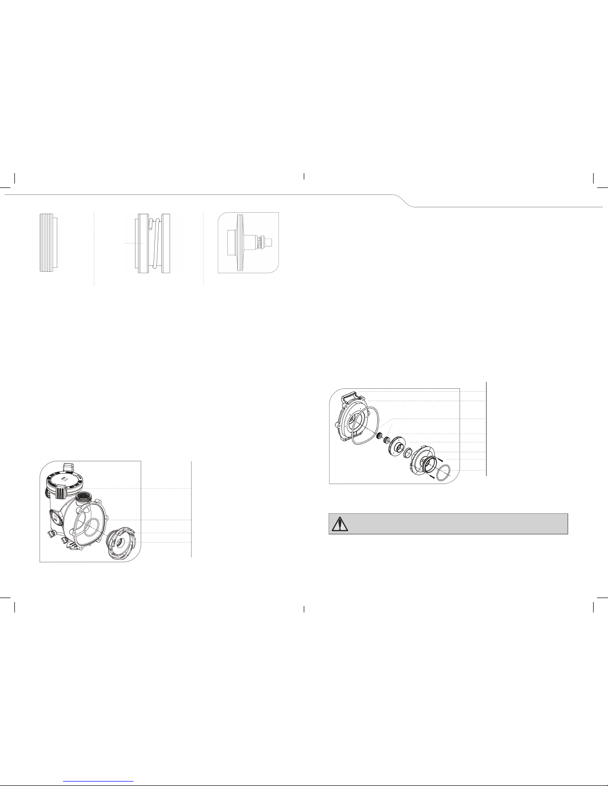
6.2.2 Impeller Removal
Before servicing the pump, turn off the pump and switch off the circuit breaker
to the pump motor. Severe personal injury, death, or property damage may
occur if the pump starts while your hand is inside the pump.
1. Turn off the pump. Switch off the circuit breaker to the pump motor. If you are not
replacing the motor, do not disconnect the electrical wiring.
NOTE: If you are replacing the motor, Zodiac strongly recommends that a qualified service
technician or electrician properly disconnect the electrical wiring at the pump motor.
6.1 Troubleshooting
SYMPTOM POSSIBLE PROBLEM/SOLUTION
The cleaning/
circulating system
is not operating
correctly.
Verify that skimmer baskets, pump basket and other screens are
clean. Clean as necessary. Check filter and clean as necessary.
Check valve positions. Adjust as necessary. NOTE: Multiple pieces
of equipment operating at one time (for example, waterfalls, spa
jets, and surface returns) may affect the cleaning system and
prevent it from working properly. Check the cleaning system
manual to ensure that the system is adjusted according to the
manufacturer's recommendations.
Bubbles/air
present in the
pump basket.
(Suction Leak)
Air in system. Check the pool or spa water level to ensure that it is
at the proper level and that air is not being drawn into the suction
piping. If the water is at the normal level, turn off the pump. Turn
the lid’s locking ring counter-clockwise until ‘START’ aligns with
the ports. Carefully remove the lid and check for debris around
the lid o-ring seat, as debris will cause air to leak into the system.
Clean the lid o-ring and place on the lid. Replace the lid with locking
ring on the pump housing. Align ‘START’ with the ports and turn
the lid’s locking ring clockwise until ‘LOCKED’ aligns with the ports.
Hand-tighten
the lid to make an air tight seal.
Do not use any
tools to tighten the lid.
Turn the pump back on.
Air leaks are still
present.
Check the suction side piping union. While the pump is running,
try to tighten the union. If this does not stop the air leak, turn
off the pump. Loosen both unions and slide the pump out of the
way. Remove, clean and re-install both union o-rings. Reposition
the pump next to the piping and secure the union nuts to the pump.
With clean union o-rings, hand-tightening of the unions should
create a seal. If the unions still do not seal, gently tighten with a
large pair of tongue-and-groove pliers.
Do not over-tighten.
There is no air in
the system, but
the pressure is still
low.
It is possible that debris is caught in the pump impeller. The pump
impeller moves the water, and the vanes in the impeller can
become blocked with debris. See
Section 6.2, Service Technician
Maintenance, 6.2.1, Blocked Impeller,
for more information.
There is no debris
blocking the
impeller and the
pressure is still
low.
The pump impeller and diffuser are showing signs of normal wear.
Have a qualified service technician check the impeller and diffuser
and replace as necessary. The pump seal might be leaking air. Have
a qualified service technician replace the seal. If the pump is part
of a relatively new installation, it could be an electrical problem.
Contact a qualified service technician. Have the technician check
for loose electrical connections and check the voltage at the
pump motor while it is in operation. The voltage must be within
10% of the motor’s data plate rating. If the voltage is not within
10%, contact a qualified electrician and/or the local power service
provider.

12 13
ZODIAC FloPro ssPump installation & Operation Manual
Figure 3. Remove the Impeller
8. Hold the motor shaft with a flat screwdriver while unscrewing the impeller from
the motor shaft with your hand. Turn the right-hand-threaded impeller counter-
clockwise to unscrew it.
9. Inspect the impeller and diffuser for signs of wearing/grinding damage.
Figure 4. Diffuser and Impeller Exploded View
6.2.3 Impeller Replacement
To avoid the risk of property damage, severe personal injury, or death, turn
off the pump and switch off the circuit breaker to the pump motor before
beginning this procedure.
To replace the mechanical seal onto the impeller sleeve press the carbon face seal half
(see Figure 5.)
using a twisting motion. Make sure the carbon surface is facing toward the
ceramic ring in the backplate.
2. Turn off any valves to prevent pool water from reaching the pump. Drain the water
from the pump by loosening the unions or removing the drain plugs.
3. Using a 14mm wrench, loosen the bolts connecting the pump body to the motor
backplate. (
See Figure 1.)
Figure 1. Remove the Pump body
4. Pull the motor and backplate out of the pump body. Remove the pump body o-ring. The
impeller is connected to the motor shaft.
5. Using a No. 1 Phillips star screwdriver, remove the two (2) screws holding the diffuser.
(The diffuser is the cover over the impeller). Then remove the diffuser.
(See Figure 2.)
Figure 2. Remove the Diffuser
6. If necessary, remove any debris in the inlet and outlet of the impeller.
7. Remove the motor fan cover on the back of the motor by removing the 4 screws holding
it in place.
(See Figure 1.)
The motor shaft with fan will be exposed.
Pump Body
Motor
Motor Backplate
Impeller Sleeve
Backplate
Bolts (6)
Screws (2)
Fan Cover
Diffuser O-ring
Diffuser
Mechanical Seal
Mechanical Seal
Impeller Sleeve
Impeller
Backplate
Diffuser O-ring
Screws (2)
Diffuser
Impeller
Backplate
Backplate O-ring

14 15
ZODIAC FloPro ssPump installation & Operation Manual
7. Slide the diffuser into the mating hole in the pump body to connect the pump body to
the backplate. While supporting the motor, start two (2) screws on opposite sides. (This
will hold the motor in position while you start the other screws.) Start the other four (4)
screws.
8. Tighten all six (6) screws lightly in a crossing “X” pattern using a 14mm wrench. Start
with the inner (middle) two (2), then tighten the outer (top and bottom) four (4) to draw
the backplate to the body in a even manner. Once all the screws are snug, torque in the
same order to 10 foot-pounds.
9. If the pump is located above the water level of the pool, remove the lid and fill the
basket with water before starting the pump.
10. Prior to replacing the lid, remove any debris around the lid o-ring seat, as debris will
allow air to leak into the system.
11. Place the lid with locking ring on the pump housing. Align ‘START’ with the ports and
turn the lid’s locking ring clockwise until ‘LOCKED’ aligns with the ports. Hand-tighten
the lid to make an air tight seal. Do not use any tools to tighten the lid.
12. Switch on the circuit breaker to the pump motor.
13. Turn on the pump and check the system for normal operation.
14. Check for any leakages.
6.2.4 Mechanical Seal Replacement
NOTE: Refer to
Figure 7
for an illustration of the location of the mechanical seal and
impeller.
Figure 7. Backplate, Impeller, Diffuser, and Mechanical Seal Exploded View
NOTE This is a two-part replacement process. The mechanical seal must be replaced
as a set.
Do not damage the ceramic or carbon surfaces of the seals. If surfaces are
damaged, leaks will occur.
1. To access the mechanical seal, comply with the warning and follow steps 1 through 8
of
Section 6.2.2, Impeller Removal.
2. Remove the carbon face seal half from the impeller sleeve.
(See Figure 5.)
This is a
spring-loaded seal. Grasp the portion of the seal closest to the impeller body and pull
the seal off using a twisting motion.
• Ceramic Face Seal
• Backplate Seal
Figure 5a. Mechanical Seal
CAUTION VERY IMPORTANT! Grasp the lower portion of the seal (opposite the carbon
face) when installing the seal or it will be damaged.
NOTE: To assist assembly, only use water or a soap solution as a lubricant. Any other
lubricant will destroy the seal after a short period of time.
NOTE: Exercise great care to keep the seal and mating parts clean.
1. While holding the motor shaft with a flat screwdriver from behind, thread the impeller
onto the motor shaft. Hand-tighten the impeller until it is secure.
2. Replace the motor fan cover and secure it with its 4 screws.
3. Replace the white impeller sleeve over the front (entry port) of the impeller.
4. Replace the diffuser over the impeller, using care to insert alignment pins into the
correct holes. The alignment pins in the diffuser allow the diffuser to be inserted only
one (1) way. Align the arrow onto the backplate with the arrows on the diffuser.
5. Replace the two (2) small Phillips-head screws. Tighten the screws to draw the diffuser
against the motor backplate.
6. Make sure the diffuser o-ring, o-ring groove, and o-ring seal area are clean and free of
debris, which could cause a leak. If you removed the diffuser o-ring during disassembly,
re-install it on the diffuser, as shown in
Figure 6.
If grease is used to retain the diffuser
o-ring, it
must be silicone based. Do not use petroleum-based grease.
It will destroy
the o-ring.
Figure 6. Pump Body and Diffuser Exploded View
Carbon Seal
Surface
• Carbon Face/Spring Side of Seal
• Impeller Side of the Mechanical Seal
Diffuser O-ring
Diffuser
Pump Body
O-ring Mounting Location
Mechanical Seal
Impeller Sleeve
Impeller
Backplate O-ring
Backplate
Screws (2)
Diffuser O-ring
Diffuser
Figure 5b. Mechanical
Seal fitted to Impeller

16 17
ZODIAC FloPro ssPump installation & Operation Manual
See Figure 8. Backplate Assembly
Section 7. Product Specifications and Technical Data
7.1 Exploded View
Zodiac
Part no. Description Qty Number on
Drawing
W77124 FLOPRO SS 0.6kW POOL PUMP 1
W70911 WET END IMPELLER ASSY 0.6KW 1 7
W77125 FLOPRO SS 0.75kW POOL PUMP 1
W70912 WET END IMPELLER ASSY 0.75KW 1 7
W77126 FLOPRO SS 1.1kW POOL PUMP 1
3. Remove the motor from the backplate following steps 1 through 3 in
Section 6.2.5,
Motor Replacement.
4. Place the backplate o-ring side down and force the ceramic seal out using a screwdriver
or drift.
5. Turn the backplate o-ring side up and insert the new ceramic seal side into the
backplate. Use great care to press the seal in squarely with your fingers. The ceramic is
easily damaged and must be pressed in using only your fingers or soft tools. Do not use
any lubricant other than water and soap solution.
6. Install the backplate to the motor following the steps in
Section 6.2.5, Motor Replacement.
7. Install the motor to the pump body following the steps in
Section 6.2.3, Impeller Replacement.
6.2.5 Motor Replacement
CAUTION: To ensure continued safety and reliable operation, Zodiac requires that
you replace the motor with a motor that has the identical kW rating and service
factor.
To avoid the risk of property damage, severe personal injury, or death, turn
off the pump and switch off the circuit breaker to the pump motor before
beginning this procedure.
1. To disassemble the pump housing from the motor, follow steps 1 through 8 in
Section
6.2.2, Impeller Removal.
2. Remove the four (4) screws connecting the backplate to the motor.
(see figure 8.)
3. Place the backplate motor assembly o-ring side down and unscrew the four (4) 14mm
screws and remove the motor.
NOTE: Before removing the backplate, note the alignment of the backplate to the motor.
See
Figure 8.
4. If installing a new motor, remove the protective plastic cap from the motor shaft.
Place the motor on the backplate the handle on the backplate is in line with the terminal
box on the motor. The terminal housing on the motor should be at the 12 o’clock position.
5. Replace the four (4) bolts and washers holding the backplate to the motor.
6. To reassemble the pump after replacing the motor, follow steps 1 through 14 of
Section 6.2.3, Impeller Replacement.
NOTE: Zodiac recommends replacing the mechanical seal at the same time that you
replace the motor. See
Section 6.2.4, Mechanical Seal Replacement,
for details.
Bolts and Washers (4)
Starting Capacitor
Backplate
Handle
Motor

18 19
ZODIAC FloPro ssPump installation & Operation Manual
W70913 WET END IMPELLER ASSY 1.1KW 1 7
W70914 DIFFUSER, PUMP, WFHPM 1 8
W70915 PUMP BACKPLATE 1 2
W70916 PUMP FOOT MOTOR 1 3
W70917 PUMP SLEEVE 1 28
W70918 PUMP ASSY. BODY FLOPRO 1 4
W70919 WET END BACKPLATE O'RING 1 24
W70920 WET END DIFFUSER O'RING 1 23
W70921A PUMP SEAL MECHANICAL (SPRING LOADED DRIVE BAND ASSY) 1 5
W70921B PUMP SEAL MECHANICAL (SEAT/MATTING RING) 1 6
W70922 WET END SCREW, MOTOR TO BACKPLATE 4 14
W70923 WET END SCREW, BACKPLATE TO PUMP 6 16
W70924 PUMP WASHER, 3/8, SS SERIES N, TYPE B, ANSI B18.2.1 10 15
W70925 WET END DIFFUSER SCREW 1 17
W70926 WET END UNION ASSEMBLY 2 1, 21, 22
W041321 REDUCING BUSH-GREY 2
7.2 Performance curves
Zodiac FloPro ssPump - Head vs Flow Rate
7.3. Physical and Operational Specifications
Figure 9. FloPro ssPump Dimensions (without Base or Spacers)
Zodiac FLOPRO Single Speed
Pump Specs 0.6kW 0.75kW 1.1kW
Model FLOPRO 0.6kW FLOPRO 0.75kW FLOPRO 1.1kW
Motor -Type Single Phase Single Phase Single Phase
Pump -kW 0.6kW / 0.75HP 0.75kW / 1.0HP 1.1kW / 1.5HP
Motor -kW 0.8kW 1.0kW 1.4kW
Motor -Voltage (Alternating Current)
and Frequency (Hertz)
V 2 3 0 A C
Hz50
V 2 3 0 A C
Hz50
V 2 3 0 A C
Hz50
Motor -Amps Maximum Amax 3.6A 4.6A 6.2A
Motor -Revolutions Per Minute RPM 2820 2820 2820
Motor -Capacitor 16µF (450V) 20µF (450V) 30µF (450V)
Insulation Class F F F
International Protection Marking IP44 IP44 IP44
Motor -Frame Size 80 80 80
Overload Protection 130°C -
Autoreset
130°C -
Autoreset
130°C -
Autoreset
Motor -Bearing Drive end 6204 DDU 6204 DDU 6204 DDU
Motor -Bearing Non Drive end 6204 DDU 6204 DDU 6204 DDU
Water Temperature Max. 35°C 35°C 35°C
Flow -Litre per minute Q(L/min) 285-205 L/min 340-240 L/min 390-260 L/min
Flow -Litre per minute Maximum Qmax 290 L/min 350 L/min 400 L/min
Head -Metres H(m) 1-12m 1-14m 1-16m
Head -Maximum Hmax 15m 17m 20m
Flow Rate Q (L/m)
Head H(m)
Zodiac
FloPro 1.1kW
Zodiac
FloPro 0,75kW
Zodiac
FloPro 0.6kW

ZODIAC CUSTOMER CARE CENTRE
Zodiac Group South Africa
Customer care line: 0860 887 665
Email: customer.care@zodiac.com
www.zodiac.co.za
Table of contents
Other Zodiac Swimming Pool Pump manuals
Popular Swimming Pool Pump manuals by other brands

Polaris
Polaris PB4-60 installation instructions

CPI
CPI Olympic 2P1815 owner's manual

STA-RITE
STA-RITE Supermax Installation and user guide

Intex
Intex Krystal Clear SF90110-1 owner's manual

Steinbach
Steinbach Speedpump FLAT TPX 3200 owner's manual

Oasis Aquatics
Oasis Aquatics M Series Installation and operation manual

Pentair Pool Products
Pentair Pool Products SuperFlo Installation and user guide

Rheem
Rheem Raypak RCAGP100 Installation and operation manual

Davey
Davey ProMaster PM200BT Installation and operating instructions

WilTec
WilTec 50253 manual

Xtreme Power
Xtreme Power 75131 Owner's manual and safety instructions

HydroPro
HydroPro Swimming Pool Heat Pump User and service manual