Bayrol Flockmatic Vario User manual
Flockmatic Vario
Version 2.1
GB
Operating manual
Flocculant dosing pump


3
Index
1GENERAL SAFETY INSTRUCTIONS.......................................................................................................4
2OVERVIEW ................................................................................................................................................ 5
3OPERATION .............................................................................................................................................. 5
3.1 Button functions.................................................................................................................................... 5
3.2 Operating states ....................................................................................................................................5
3.3 Menu structure.......................................................................................................................................6
3.4 Menu items............................................................................................................................................. 6
4INSTALLATION AND MAINTENANCE..................................................................................................... 7
4.1 Safety instructions for installation and mintenance tasks................................................................ 7
4.2 Mounting................................................................................................................................................. 7
4.3 Electrical connection............................................................................................................................. 7
4.4 Replacing the device fuse ....................................................................................................................7
4.5 Installation in the circulation system .................................................................................................. 8
4.6 Maintenance...........................................................................................................................................8
4.6.1 14-day maintenance............................................................................................................................8
4.6.2 Yearly maintenance.............................................................................................................................8
4.6.3 Cleaning ..............................................................................................................................................8
4.6.4 Hose replacement Flockmatic Vario ...................................................................................................8
4.7 Winter care ............................................................................................................................................. 9
4.8 Decommissioning..................................................................................................................................9
5TECHNICAL DATA.................................................................................................................................... 9
6SPARE PARTS..........................................................................................................................................9
4
1General safety instructions
This operating manual contains basic instructions that must be
complied with for installation, commissioning, operation, and
maintenance. Consequently this operating manual must always
be read by the fitter as well as the responsible owner prior to
installation and commissioning, and must be accessible to
every user of the device. In addition, all other safety
instructions in this document must be strictly complied with.
Read and comply with all instructions.
To reduce the danger of injury, do not allow children to use this
product.
Dangers due to failure to comply with the safety
instructions
Failure to comply with the safety instructions can result in
hazards for personnel as well as for the environment and the
device.
Failure to comply with the safety instructions can result in loss
of all claims for damage compensation.
DANGER!
Inadequate qualification of personnel
Dangers due to inadequate qualification of
personnel!
Possible consequence: Death or severe injury,
significant damage to material assets.
The system owner must ensure compliance
with the required qualifications.
All activities must only be carried out by
personnel who are qualified to perform such
activities.
Access to the system must be prevented for
inadequately qualified personnel..
IMPORTANT NOTE!
Compliance with the applicable accident
prevention regulations and the other statutory
regulations and the generally acknowledged
safety regulations must be ensured by the system
owner!
IMPORTANT NOTE!
Only liquid flocculants from the company
BAYROL may be dosed with the Flockmatic
Vario. The use of flocculants or other products
from other manufacturers results in loss of all
damage compensation claims!
DANGER!
Compliance with the protection rating
After tasks on the Flockmatic Vario, if the housing
or individual cable glands are not properly closed,
so that a reliable seal is ensured, moisture can
penetrate into the device.
Possible consequences: Damage or
destruction of the Flockmatic Vario,
malfunctions.
After all tasks performed on the device,
ensure a safe seal..

5
2Overview
The Flockmatic Vario is a high quality peristaltic pump for
dosing of liquid flocculants in the circulation circuit of a
swimming pool.
The swimming pool must be equipped with an adequately
dimensioned sand filter system.
3Operation
The Flockmatic Vario is operated via the two-row display with 2
x 16 characters and the membrane pushbuttons.
3.1 Button functions
Button
Function
Switches from the basic view to the menu
structure.
-Switches from the menu structure back
to basic view.
-Switches from one menu item to the
next higher menu item.
-When exiting an input menu the
selected settings are not applied.
-Opens the input menu of a menu item.
-Confirms the changed settings in an
input menu.
and
-Navigates between the individual menu
items.
-Changes the setting values in the input
menu.
3.2 Operating states
Status
Description
Off
The display is switched off, the pump does
not display, the filling level of the canister
for flocculent is not evaluated, and no
input can be made. The green LED
flashes at intervals of approx. 2 sec.
Activate the button for approximately
1 second to switch on the device; the
device is in operating status Off.
On
The green LED flashes briefly at
intervals of approx. 2 sec, the display is
switched on and inputs can be made.
Briefly activate the button to switch
the device to automatic mode.
Dosing
The green LED is illuminated
continuously. The display is switched on
and inputs can be made.
If the filling level of the canister for
flocculent is low, an alarm will be
triggered.
Fast vacuum function:
With this function the air can be quickly
removed from the suction and pressure
hose. For this, the dosing pump is
switched on manually with the
button for approximately one minute with
full capacity. Subsequent pushing of the
button switches off the pump as
needed before one minute elapses.
6
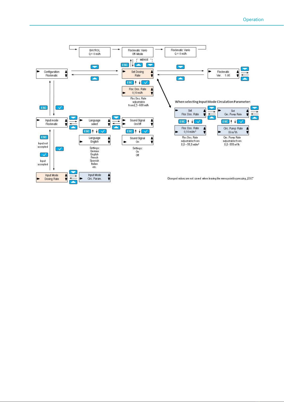
3.3 Menu structure
3.4 Menu items
Basic view:
In the basic view the momentary delivery capacity is displayed,
and in operating status Off, the current mode is displayed.
Flockmatic configuration:
Input mode - delivery capacity
There are 2 possibilities for entering the delivery capacity:
1. Input mode dosing capacity
If this input mode is selected the delivery capacity is
entered directly in ml/h (from 2.5 - 600 ml/h)
2. Input mode - circulation parameters
If this input mode is selected the delivery capacity is
calculated based on the two parameters "dosing
quantity" and "circulation" that must be input.
The necessary dosing quantity of flocculent per m3of
circulation capacity depends on the concentration of
the flocculent used.
The circulation capacity is set in accordance with the
circulation pump used.
Available languages
The device can be configured for multiple languages.
Acoustic signal
The acoustic signal that is triggered when the filling level
of the canister for flocculent is low, can be activated or
deactivated. The visual alarm signal will always be output
regardless of this setting.
Output of the alarm via the PoolManager®/Analyt
(only devices with colour display):
If an alarm should not be output via the Flockmatic Vario,
but rather should be output via one of the devices cited,
then the BNC connector of the suction lance is connected
directly to the control device. In this case the input on the
Flockmatic Vario must be bypassed with a BNC
terminating connector.
In this case the Flockmatic Vario must be connected via
the module in the PoolManager®/Analyt that is provided for
this purpose.
See the PoolManager®/Analyt manual for more
information on connection and configuration.

7
4Installation and maintenance
4.1 Safety instructions for installation
and mintenance tasks
DANGER!
Danger due to electric shock
The Flockmatic Vario is energised as soon as
voltage is applied on the mains input. Contact
with energised parts can result in electric shock.
Possible consequence: Serious or fatal
health impairment, damage to material
assets
Installation and maintenance tasks on the
device must always be executed in de-
energised status.
When performing tasks safeguard the
device from being switched on!
Only connect cables in de-energized status.
A safety device that is independent of the
pump should always be present .
The valid country-specific safety regulations
must be complied with.
Directly after completing the tasks, all safety
devices and protective devices must be
reattached, i.e. must be rendered functional.
Failure to comply with the safety instructions
can result in defects of the device and life-
threatening danger, with the consequence
of loss of warranty.
4.2 Mounting
Level, vertical surface.
The free area surrounding the device must be large enough
to ensure that trouble-free operation and maintenance are
possible. The cover must always be removable.
Pump housing vertical, hose connections downwards.
The display of the regulator should be approximately at eye
level.
Below the device, at least 20 cm of free space is required
for installation of the hoses.
There must be no parts that are sensitive to moisture below
the device.
A wet room earth contact electrical outlet with continuous
current at a maximum distance of 1.5 m.
All hoses and cables must be laid out in such a manner that
they are kink-free and free of abrasion.
No hose line should be longer than 5 m
The hoses must not be routed directly over heat-conducting
pipes or systems.
Direct sunlight, thermal radiation, the effects of frost and
moisture must be avoided.
Ensure adequate aeration.
Ensure that measures are in place in the event of a leak in
the pump or the dosing hoses (e.g. defined discharge,
collecting container).
The base plate can be used as a drilling template by
holding it at the intended location and marking the location
of the bores on the wall..
4.3 Electrical connection
The Flockmatic Vario has been designed and built in
accordance with the applicable guidelines. Prior to leaving the
plant the product was carefully tested and it left the plant in
faultless condition.
Safe operation is only possible if all instructions contained in
this manual and the generally applicable guidelines are
complied with.
The supply voltage for the device must not exceed 240 V/50
Hz. The permitted operating temperature is 5 to 45ºC, the
permitted humidity is 0-90%.
As is customary for all electrical connections, ensure that all
plug connections are protected against water.
IMPORTANT NOTE
Ensure that the Flockmatic Vario is only
supplied with power when the circulation pump
is running!
4.4 Replacing the device fuse
If the device is subjected to an unusual operating state, this can
cause a fuse to trip; in this case the fuse must be replaced.
IMPORTANT NOTE
Always identify what caused the fuse to trip.
Always ensure that the cause is completely
eliminated before placing the Flockmatic Vario
is service again.
Replacing a fuse:
Disconnect the Flockmatic Vario from the power supply.
Remove the pressure and suction hose.
Take the cover off of the rotor.
Pull off the blue housing frame from the front.
Open the housing by unscrewing the 4 Phillips head
screws.
Pull off the upper part of the housing from the front.
Turn the cover of the black fuse holder a quarter turn to the
left and pull the fuse up and out.
Insert a new (1 A/250 V MT) fuse.
Assembly is executed in the reverse sequence.

8
4.5 Installation in the circulation system
Install the Flockmatic Vario in the circulation system as follows.
1 Flockmatic Vario
2 Quickflock fluid
3 Heat exchanger
4 Filter
5 Injection after the circulation pump
6 Filter pump
7 Injection before circulation pump
(recommended if counter pressure is higher than 0.8 bar)
Connect the suction hose (connection to the canister) on the
left connection of the pump, connect the pressure hose
(connection to the injection nozzle) on the right connection of
the pump.
IMPORTANT NOTE
For all hose and mounting connections, ensure
that these connections do not leak.
Liability is excluded if there are leaks!
4.6 Maintenance
Some parts of the Flockmatic Vario are subject to wear due to
chemical and mechanical stress. Thus regular inspection is
required for safe, long-term operation. Regular preventive
maintenance of the system protects against unscheduled
interruptions of operation.
4.6.1 14-day maintenance
Visual inspection of all dosing lines and the dosing hose
for leaks, replace if necessary
4.6.2 Yearly maintenance
Visual inspection of all dosing lines, replace if necessary
Replacement of the hose of the dosing pump
4.6.3 Cleaning
Clean the surfaces of the device with a soft lint-free cloth as
needed. To do this only use a little water, if necessary
IMPORTANT NOTE
Do not use aggressive cleaners
4.6.4 Hose replacement Flockmatic Vario
NOTE
Never grease the hose!
NOTE
Only use original spare pump hoses!
DANGER!
Danger due to chemicals
When pulling off the pump hose, corrosive
product residues can escape.
Possible consequence: Serious health
impairment (acid burns) and damage to
material assets
Always empty the pump hose and supply
lines first.
If necessary wear protective goggles and
protective gloves and protect the
surroundings against escaping product
residues with a cloth.
DANGER!
Danger due to rotating parts
The rotor of the dosing pump can start-up
abruptly.
Possible consequence: Danger of crushing
for fingers!
Ensure that the dosing pump remains
disconnected from the operating voltage while
replacing the hose (unplug the mains plug)!
The hose of the dosing pump is replaced without dismounting
the rotor.
Remove the emptied suction and pressure hoses from the
hose holder. To do this open the blue clamping screws.
Take the transparent cover 1 off of the pump.
Take off the blue cover 2 of the rotor.
Turn rotor 3 in such a manner that the flat side points to
the left and is vertical.
Pull the hose holder 4 out of its holder and lift it on the left
side.
Now turn the rotor 3 clockwise and follow with the hose
lifted until it is completely free.
Proceed in the reverse sequence for mounting.
The hose only, or the hose together with the hose holder can
be replaced.

9
We recommend replacing the hose together with the hose
holder. (Replacement hose set)
Art.-no.
Description
127402
Replacement hose Flockmatic / Vario S
127403
Replacement hose set Flockmatic / Vario S
NOTE
If only the hose is replaced, you must strictly
ensure the following when mounting the hose
Firm seat of the hose on the nozzles.
The hose must not be fitted on twisted under
any circumstances.
You must ensure that the hose connectors
are firmly seated..
4.7 Winter care
For brief interruption of use (e.g. several days) no special
measures are required.
For longer interruptions of operation that extend over several
weeks, as in the case of winter care the following tasks must be
executed:
Remove the suction lance from the canister and rinse it with
water.
Seal the delivery container, store it in a cool and dry
location and protect against UV radiation.
Rinse the hose pump with water.
Take the dosing hose out of the pump.
Flush all hoses with water and empty them completely.
After the winter season, all components must be examined to
determine that they are functional. All dismounted parts must
be remounted at their intended position. Check the settings of
the Flockmatic Vario.
4.8 Decommissioning
If the device will be disposed of after its service life, it must be
flushed out and the water drained. The device has been
manufactured in accordance with the provisions of the ROHS
Directive and the Waste Electrical and Electronic Equipment
Directive. It does not belong in domestic waste.
Take the device to a suitable and appropriate collection point.
5Technical data
Parameter
Value
Supply voltage
230VAC
Power consumption
max. 20VA
Ambient temperature
min.5 - max. 45°C
Delivery capacity
2,5 –600ml/h
Counterpressure
max. 3 bar
Protection class -
housing
P65
Dimensions
(without mounting plate):
approx. 93 x 150 x 130 mm
(WxHxD)
6Spare parts
Art.-No.
Picture
Description
127 450
Flockmatic Vario
172 130
Suction fitting, rigid PR
127403
Replacement hose set
Flockmatic / Vario S
127402
Pump hose Flockmatic /
Vario S
100 509
PE dosing hose 6x4X1
(10 m)
171 207
Injection nozzle, 0.5 bar
Table of contents
Popular Swimming Pool Pump manuals by other brands


Polygroup
Polygroup SUMMER WAVES ST1100 owner's manual

NOVARDEN
NOVARDEN NSH35s Installation and user manual

Dankoff Solar Products
Dankoff Solar Products SunCentric P instruction manual

Badu Tec
Badu Tec Eco Touch Series Original installation and operating manual

Pentair
Pentair SWIMMEY Series installation guide

Hayward
Hayward TriStar Waterfall owner's manual


