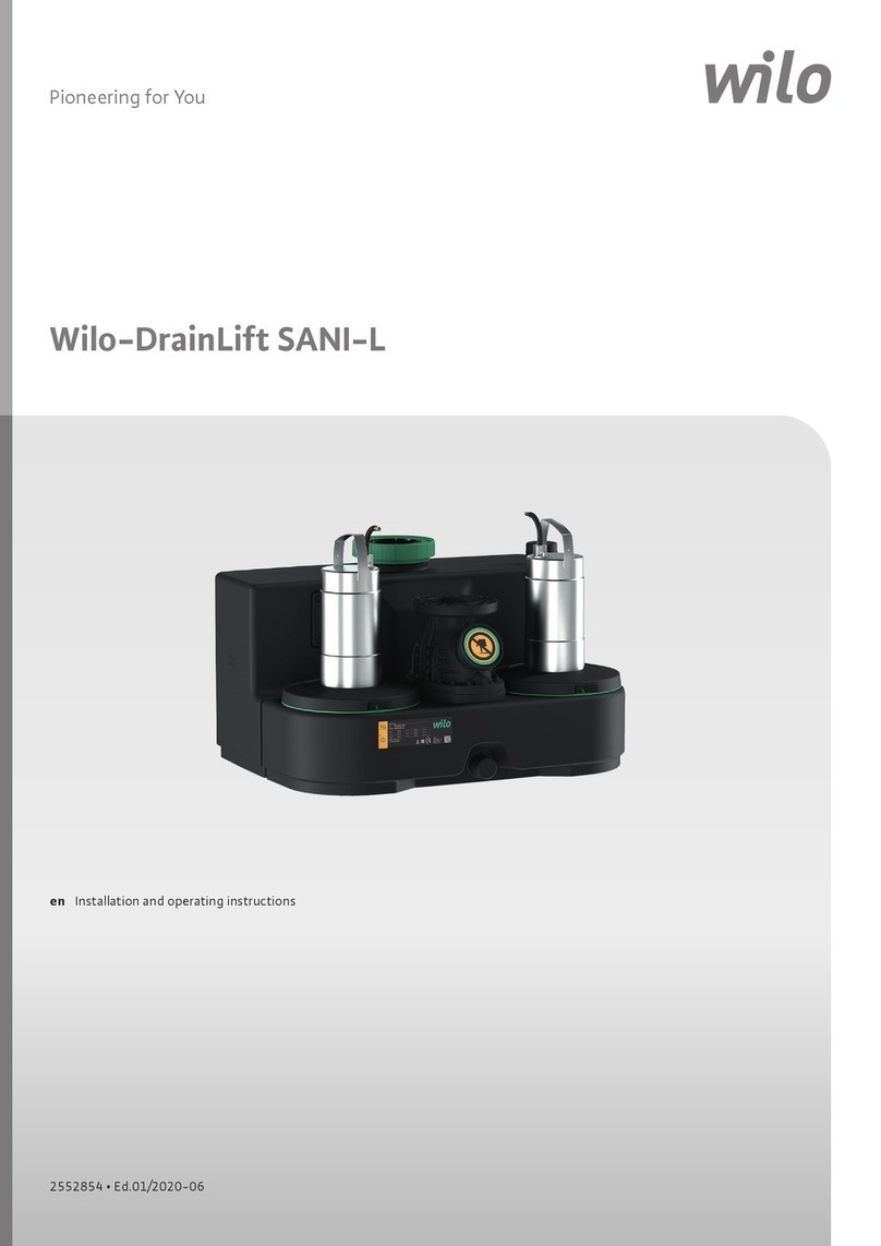
Installation and operating instructions Wilo-DrainLift S 29
PRODUCT DESCRIPTION English
The lifting unit must not be used for pumping
• Debris, ash, garbage, glass, sand, plaster, cement,
lime,mortar,brousmaterials,textiles,paper
towels,wet‑wipes(e.g.eececloths,moisttoilet
paper wipes), nappies, cardboard, coarse paper,
synthetic resins, tar, kitchen waste, grease, oil
• Slaughterhouse waste, disposal of slaughtered
animals and animal waste (liquid manure, etc.)
• Toxic, aggressive and corrosive substances, such
as heavy metals, biocides, pesticides, acids, bases,
salts, swimming-pool water
• Cleaning agents, disinfectants, dishwashing or
laundry detergents in excess amounts, and such
which have a high degree of foam formation
• Sewage from drainage objects which lie above the
backowlevelandcanbedrainedbymeansof
gravity(acc.toEN12056‑1)
• Explosive media
• Drinking water
be used.
The system must be installed in accordance with
thegeneralrulesasdetailedinEN12056and
DIN1986‑100.
Intended use includes compliance with this man-
ual. Any other use is regarded as non-compliant
with the intended use.
3.1.1. Application limits
DANGER due to overpressure
Exceeding the application limits can result in
excessive pressure in the collection reservoir
if the unit malfunctions. This can cause the
collection reservoir to burst! There is a health
risk due to contact with sewage polluted by
bacteria (faeces). Always comply with the
application limits and ensure that the inlet is
blocked if the unit malfunctions.
The following application limits must be observed
strictly:
• Max.intake/h:600l
The maximum inow must always be less than
the volume ow of the pump at the respective
duty point.
• Max.suctionhead:5m
• Max.permittedpressureinpressurepipe:1.5bar
• Max.uidtemperature:40°C,60°Cformax.
3min
• Max.ambienttemperature:40°C
• Operatingmode:S315%,120s
The unit is not designed for continuous duty!
The maximum volume ow applies to intermit-
tent periodic duty according to EN60034-1!
• Also comply with further information in the
“Technical data” section!
3.2. Set-up
The Wilo-DrainLift S is a submersible, fully
automatic sewage lifting unit that is ready for
connection as a single-pump system.
Fig. 1: Description
1 Collection reservoir 6 Inlet DN 40
2 Inspection opening 7 Ventilation connection
3 Level control 8 Pressure connection
4 Motor 9 Fastening straps
5 Free choice of inlet surface areas
3.2.1. Collection reservoir
Gas and water-tight collection reservoir made
from PE plastic with tapering collection chamber
for reliable operation without any build-up of
deposits.
TheinletconnectionsDN100canbeselectedas
required on both sides and on the longitudinal
side.ThepressureconnectionDN80iscongured
vertically above the reservoir. Furthermore, the
liftingunithastwoinletconnectionsDN40and
oneventilationconnectionDN70.
For simple maintenance of the unit, the collection
reservoir is equipped with an inspection opening.
Furthermore, the reservoir also has two fastening
straps. This allows the lifting unit to be anchored
in an anti-buoyant way to the ground with the
suppliedxationmaterial.Thefasteningstraps
also function as transport carrying handles.
3.2.2. Motor
The motor that is mounted is a watertight,
encapsulated dry motor with a stainless steel
housing. The cooling is done by the ambient air.
The waste heat is given off via the motor housing.
The motor is equipped with a thermal winding
monitorwithbimetallicstrips:
• The winding monitoring for the three phase
motor is displayed and reset via the connected
switchgear.
• The winding monitoring for the AC motor is au-
tomatically switching. This means that the motor
is switched off if it overheats and is automatically
switched on again when it has cooled down.
3.2.3. Level control
Thelevelcontrolisttedinthecollection
reservoir.Rodoatswitchesareusedassignal
transmitters. The switching points for “Pump ON”
and “High water alarm” are pre-set. The switch-
ingpointfor“PumpOFF”isdenedbytheset
follow-up time of the pump.
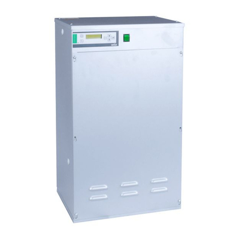
3.2.4. Switchgear
Thesystemiscontrolledviathettedswitchgear.
The switchgear can also be used to implement
a collective fault signal (SSM). The cable length
from the motor to the switchgear is 4 m and from
switchgear to plug 1.5 m. Detailed information
about the switchgear can be found in the en-
closed installation and operating instructions.
For exact details on connection, see the con-
nection diagram in this operating and mainte-
nance manual.
