manuals.online logo
Brands
  1. Home
  2. •
  3. Brands
  4. •
  5. Wilo
  6. •
  7. Water Pump
  8. •
  9. Wilo Scot Pump MOTORPUMP 230 Owner's manual

Wilo Scot Pump MOTORPUMP 230 Owner's manual

MOTORPUMP™
zINSTALLATION zOPERATION zMAINTENANCE
INCLUDES MECHANICAL SEAL REPLACEMENT
Check pump for shortage and damage immediately upon
arrival. Note damage or shortage on freight bill (bill of
lading); immediately file claim with carrier.
EXTERIOR — Pay particular attention to conduit box,
external hardware and accessories. Touch up abrasions
or scratches with approved paint.
INTERNAL — If extensive or serious external damage
is noted, if impeller is damaged (look in ports), or if shaft
binds or sticks, disassemble as required to permit
internal inspection.
Handle with care. Dropping or jarring can seriously dam-
age motor bearings or break pump parts. Lift with device
having capacity for pump weight, and use lifting hooks or
eye bolts (if provided) or rig double sling around motor
frame and pump casing. Do not use sling through pump
motor adapter nor around suction and discharge flanges.
Location — Pump location should provide the following:
1. Install as close to suction supply as possible.
2. Shortest and most direct suction pipe practical.
Suction lift must not exceed limit for pump. NPSH
available must equal or exceed pump requirement.
3. Suction port below pumping level to provide priming.
4. Use caution when mounting pumps with mounting
base affixed to case. When the motor base and
mounting feet of the case are not on the same plane,
install a riser or shim under the motor mounting feet.
Ensure the pump case feet are flush with the moun-
gin platform, Do not over-tighten to pull case down
to meet platform.
5. Room for inspection and maintenance.
6. Correct power supply to motor; all wiring should
meet National Electrical and Local Codes and
Regulations.
7. If outdoors, protection from the elements, freezing
and water damage due to flooding.
Piping — Suction and discharge gauges are useful to
check pump operation and are excellent trouble indica-
tors. Install gauges in the lines if pump ports do not have
gauge taps. Observe these precautions when installing
piping:
1. Support close to, but independently of pump.
2. Use the next larger pump size for suction and dis-
charge.
3. Keep as straight as possible. Avoid bends and fit-
tings.
4. Remove burrs, sharp edges, ream pipe cuts, and
make joints air-tight.
5. Don’t spring pipe to make connections. Strain must
not be transmitted to pump.
6. Allow for pipe expansion with hot fluids; expansion
joints are not recommended.
Suction — Size and install suction piping to keep pres-
sure loss at minimum and to provide correct NPSH by
observing the following:
1. The suction pipe should be equal in size or preferably
one size larger than the suction connection of the
pump. If pipe is larger than the pump suction, an
eccentric pipe reducer should be used at the pump.
2. Pipe should slope upward to pump, even for horizon-
tal run.
3. Use 45-degree or long-sweep 90-degree elbows.
4. A valve in the suction is necessary only on positive
suction head installation and must not be used to
throttle the pump. The suction valve should be
installed for maintenance purposes only.
Discharge — Pumps permit discharge port location at
two positions, 30 degrees apart. Change by removing
cover bolts, rotate casing, and replace bolts. Do not slice
O-ring. Scot does not recommend bottom vertical, 3:00
or 9:00 discharge positions due to erratic pump perfor-
mance. Ensure there is adequate clearance with selected
position between wall or tank, motor conduit box, and
grease fittings. Casing may extend beyond base or feet.
1 Short discharge lines may be the same size as the
discharge port. Long runs require a pipe larger than
INSTALLATION
HANDLING
61.000.281
DECEMBER 2017
• Cedarburg, WI 53012 • P.O. Box 286 • 262-377-7000 • FAX 262-377-7330
Scot Pump A Wilo Company — Main Office and Manufacturing Facility
J56 & JM FRAME
304 STAINLESS STEEL
PUMP NO. 230-232, 236, 320-328
Replaces Nov 2009
the discharge port.
2. Long horizontal runs require a grade as even as pos-
sible. Avoid high spots and loops. Trapped air will
throttle flow and may result in erratic pumping.
3. Install check and gate valves in discharge line; check
valve (if used) between pump and gate valve.
Pre-Start — Before initial start of the pump, check as
follows:
1. The rotation must be checked upon installation.
Close, then break the contacts quickly and observe
the rotation of the exposed portion of the rotating
parts. Rotation must agree with the rotation arrow on
the motor. For all pumps, the standard rotation is
counterclockwise when viewed from the suction
end. Motor wiring is easily changed in the field.
Observe the wiring diagram on the inside of the ter-
minal box cover, or on the motor nameplate.
2. Check voltage, phase and frequency of line circuit
with motor nameplate.
3. Check suction and discharge piping and pressure
gauges for proper operation.
4. Assure that pump is full of liquid (primed).
Priming — If pump is installed with a positive head on
the suction, prime by opening suction valve and allowing
liquid to enter the casing, at the same time venting all air
out of the top of the casing.
If pump is installed with a suction lift, priming must be
done by other methods, such as foot valves, ejectors, or
by manually filling casing and suction line.
CAUTION - DO NOT RUN PUMP DRY. Serious damage
may result if started dry.
Starting — Proceed as follows to start pump:
1. Close drain valves and valve in discharge line.
2. Open fully all valves in the suction line.
3. Prime the pump. If pump does not prime properly, or
loses prime during start-up, shut down and correct
condition before repeating procedure.
4. For pumps moving high temperature liquids, open
warm-up valve to circulate liquid for preheating.
Close valve after pump has warmed up.
5. Start the motor (pump).
6. When pump is operating at full speed, open dis-
charge valve slowly.
Running — Periodically inspect pump while running,
but especially after first start and following repair.
1. Check pump and piping for leaks. Repair immediately.
2. Record pressure gauge readings for future reference.
3. Record voltage, amperage per phase, and kW (if an
indicating wattmeter is available).
4. Adjust pump output capacity with discharge valve.
DO NOT throttle suction line.
Freezing Protection — Protect pumps shut down
during freezing conditions by one of the following meth-
ods:
1. Drain pump; remove all liquid from the casing.
2. Keep fluid moving in pump and insulate or heat the
pump to prevent freezing. If heated, do not let tem-
perature go above 100 to 150 degrees F.
3. Fill pump completely with antifreeze solution.
Cleaning — Remove oil , dust, dirt, water, chemicals
from exterior or motor and pump. Keep motor air inlet
and outlet open. Blow out interior of open motors with
clean compressed air at low pressure. Regularly drain
moisture from TEFC motors.
Temperature — Total temperature, not the rise, is the
measure of safe operation for a motor. If temperature by
thermometer exceeds limits for insulation class, investi-
gate and change operating conditions.
Labeled Motors — It is imperative for repair of a
motor with Underwriters’ Laboratories label that original
clearances be held; that all plugs, screws, other hard-
ware be fastened securely, and that parts replacements
be exact duplicates or approved equals. Violation of any
of the above invalidates Underwriters’ label.
Lubrication — Pumps should require no mainte-
nance, other than the motor bearings, according to the
following instructions:
DOUBLE SHIELDED. When double shielded prelubricat-
ed bearings are furnished, no lubrication is required for
the life of the bearings. Inspect bearings periodically to
determine the condition of the grease and replace the
bearings if necessary.
SINGLE SHIELDED W/GREASE FITTING PROVISIONS.
When single shield bearings are furnished, periodic
inspection, cleaning and relubrication is required. See
motor manufacturer’s specific instructions for
lubrication.
J56 FRAME MOTOR, PUMP NO. 230, 231, 232
A.) Disassembly:
1. Turn off power.
2. Close suction and discharge valves.
3. Drain pump.
4. Remove bolts holding base to foundation
5. Remove pipe connections from suction and dis-
charge.
6. Remove pump from system.
7. Remove case.
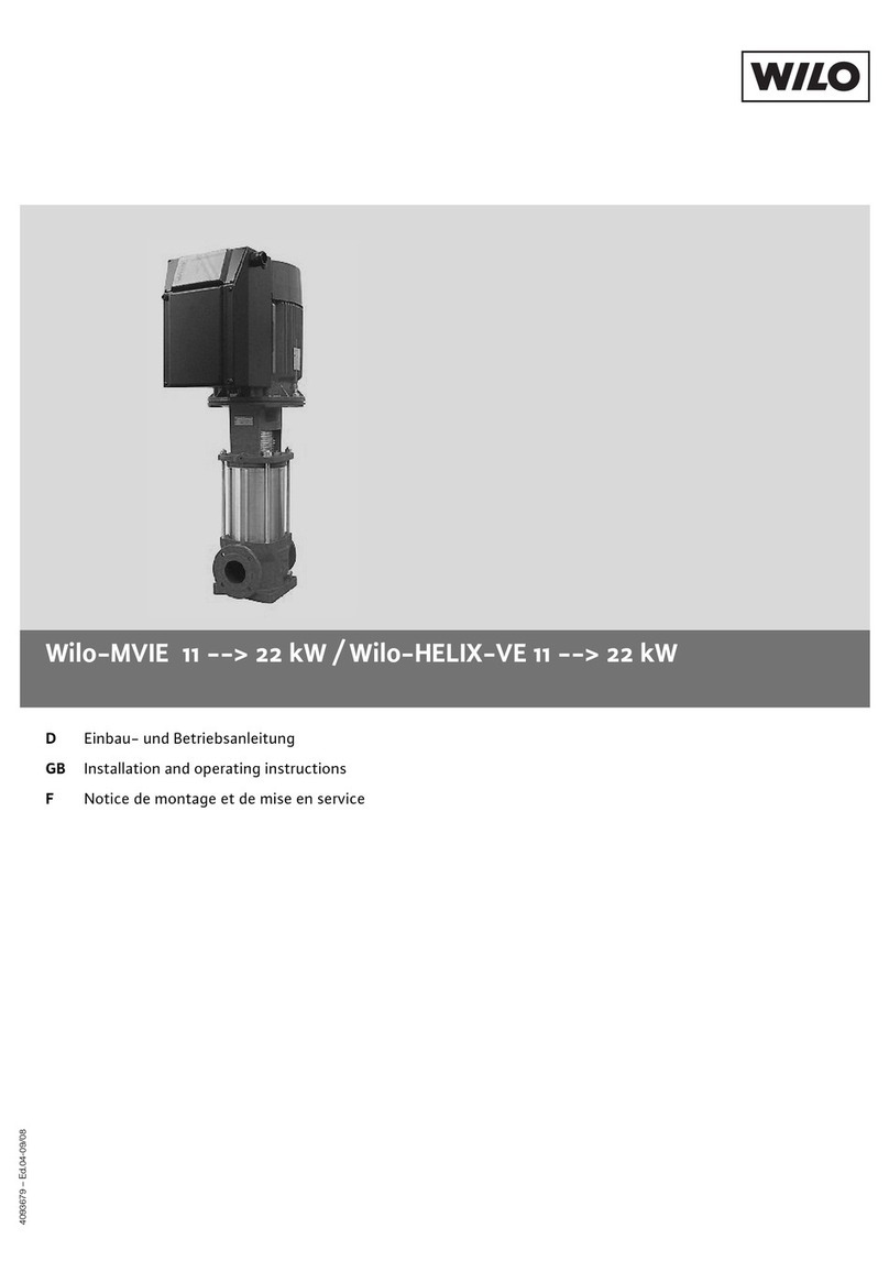
8. Insert a screwdriver in one of the impeller water-
way passages and back off the impeller nut as
shown in Figure 1.
9. Remove motor shaft end cap. Insert a screw-
driver in slot of motor shaft. While holding shaft
against rotation, unscrew impeller from shaft by
MECHANICAL SEAL REPLACEMENT
MAINTENANCE
OPERATION
Figure 1
turning counterclockwise when facing impeller
(Figure 2).
10. Pry off rotating member of mechanical seal
from motor shaft by using (2) screwdrivers. Be
careful not to damage the pump cover. See
Figure 3.
11. Remove pump cover from cast iron disc. (There
is no hardware used to attach cover to disc.)
Place cover on a flat surface with convex side
down. Push out stationary member of mechani-
cal seal. It is not necessary to remove the cast
iron disc from the motor to replace the seal.
B.) Reassembly:
CAUTION: The mechanical seal is a precision prod-
uct and should be handled accordingly. Use care
when handling lapped running surfaces of the
mechanical seal to ensure they remain clean and are
free of chips or scratches.
1. Clean gasket and flange faces, seal seat cavity
and shaft, in particular shaft shoulder fitting
against impeller.
2. Position the stationary seat with the silver dot
down (away from you) and the lapped face (shiny
side) facing you. Lubricate the seal seat cavity of
the cover and the rubber cup or O-ring of sta-
tionary seal seat with the lubricating fluid that
comes with the mechanical seal or repair kit.
Press the stationary seat in seal seat cavity in the
cover squarely and evenly using a arbor press (if
possible) and the cardboard disc supplied with
the seal. Be certain that the lapped face (shiny
side) is facing you.
3. Position the cover so that the convex side with
the lapped seal seat is facing you. Place the
cover on the motor disc and align the holes in the
disc with the holes in the cover. (Note: There
isn’t any hardware required to attach the cover to
the motor disc.)
4. Apply the lubricating fluid that comes with the
mechanical seal or repair kit to the motor shaft
and the rubber bellows of the rotary seal. Slide
the seal head on the shaft, press the rubber drive
band on the rotary head until the lapped face on
the head seats firmly against the lapped face of
the stationary seat. Install seal spring on head
and seal spring retainer on spring. Do not chip
or scratch faces during installation. Take extra
care to make sure the lapped faces are clean.
5. Hold shaft against rotation as described in para-
graph 8 of disassembly procedure, and thread
impeller on shaft until it is tight against the shaft
shoulder. The impeller will compress the seal
spring to the proper length assuring correct
pressure on lapped faces.
6. Replace D-washer and impeller nut holding
impeller against rotation as indicated in para-
graph 7 of disassembly procedure (2 & 3 HP 1PH,
and all 3PH motors only).
7. Remove any burrs caused by screwdriver on the
vane of impeller in waterway passage.
8. Install O-Ring on cover. Be sure that any dam-
aged O-ring is replaced.
9. Place pump casing against pump cover. Ensure
that impeller eye is centered in pump case and
position case, cover and motor disc so that the
holes line up. Install socket head cap screws
through the case and cover, and thread into the
motor disc. Tighten all cap screws alternately
and evenly until finger tight.
10. Finish tightening the cap screws alternately and
evenly to approximately 6 ft. lbs. torque. Note: It
is imperative that the screws be tightened alter-
nately and evenly, as this action centers the
cover in the casing, assuring proper alignment.
Binding of the impeller in the case may occur if
the case is not positioned properly and/or the
cap screws are not tightened as indicated.
11. Replace hold-down bolts.
12. Check for free rotation after assembly is com-
pleted.
13. Replace motor shaft end cap.
14. Seal all drain openings using pipe sealant on
threads.
15. Reprime before starting. Do not start until pump
is completely filled with water.
JM FRAME MOTOR, PUMP NO. 236, 320-328
A.) Disassembly:
1. Turn off power.
2. Close suction and discharge valves.
3. Drain pump.
4. Remove bolts holding down pump to mounting
plate.
5. Remove pipe connections from suction and dis-
charge.
6. Remove pump from system.
7. Remove case.
8. Insert a screwdriver in one of the impeller water-
way passages, as shown in Figure 4, and back off
the impeller retaining assembly with a socket
wrench.
9. Remove impeller from shaft, being careful not to
lose the impeller key, spring and gasket. If
impeller is difficult to remove, it may be neces-
sary to use a bearing puller to remove.
10. Pry off rotating member of mechanical seal from
sleeve by using two (2) screwdrivers. Be careful
MECHANICAL SEAL REPLACEMENT
Figure 2
Figure 3
not to
damage the pump cover. See Figure 5.
11. Remove pump cover from cast iron disc. (There
isn’t any hardware used to attach cover to disc.
Place cover on flat surface with convex side
down, and push out stationary member of
mechanical seal. It is not necessary to remove
cast iron disc from motor to replace seal.
12. Inspect shaft sleeve. If damaged or worn,
remove from shaft and replace.
B.) Reassembly:
CAUTION: The mechanical seal is a precision prod-
uct and should be handled accordingly. Use care
when handling lapped running surfaces of the
mechanical seal to ensure they remain clean and are
free of chips or scratches.
1. Clean gasket and flange faces, seal seat cavity,
shaft sleeve, and motor shaft.
2. Position cover so that the convex side is facing
you. Position the stationary seat with the silver-
dot down (away from you) and the lapped face
(shiny side) facing you.Lubricate the seal seat
cavity of the cover and the rubber cup or O-ring
of seal seat with the lubricating fluid that comes
with the mechanical seal or repair kit. Press the
stationary seat in seal seat cavity of the cover
squarely and evenly using a arbor press (if pos-
sible) and the cardboard disc supplied with the
seal. Be certain that the lapped face (shiny side)
is facing you.
3. Install the flinger on the motor shaft until it
bottoms on the motor shaft.
4. Slide the shaft O-ring on the motor shaft until it is
tight against the flinger. Make sure that the shaft
O-ring does not get damaged during this proce-
dure.
5. Position the cover so that the convex side with
the lapped seal seat is facing you. Place the
cover on the motor disc and align the holes in the
disc with holes in the cover. (There isn’t any
hardward required to attach cover to motor disc.)
6. Apply the lubricating fluid that comes with the
mechanical seal or repair kit to the motor sleeve
and the rubber bellows of the rotary seal. Slide
the seal head on the shaft sleeve, press the rub-
ber drive band on the rotary head until the lapped
face on the head seats firmly against the lapped
face of the stationary seat. Do not chip or
scratch faces during installation. Take extra care
to make sure the lapped faces are clean.
7. Install the seal spring on the seal head and
retainer on spring.
8. Place key in key seat. Line up keyway in impeller
with key on motor shaft, and slide impeller on
motor shaft. Be certain that the key is positioned
in the keyway of the motor and impeller. Slightly
compress seal spring with impeller and hold
impeller while installing impeller retaining
assembly in motor shaft.
9. Insert a screwdriver in a waterway passage of
the impeller holding it against rotation as dis-
cussed in paragraph 7 of the disassembly
instructions.
10. Remove any burrs caused by screwdriver on the
vane of impeller in waterway passage.
11. Install O-Ring on cover. Be sure that any dam-
aged O-ring is replaced.
12. Place pump casing against pump cover. Ensure
that impeller eye is centered in pump case and
position case, cover and motor disc so that the
holes line up. Install socket head cap screws
through the case and cover, and thread into the
motor disc. Tighten all cap screws alternately
and evenly until finger tight.
13. Finish tightening the cap screws alternately and
evenly to approximately 6 ft. lbs. torque. Note: It
is imperative that the screws be tightened alter-
nately and evenly, as this action centers the
cover in the casing, assuring proper alignment.
Binding of the impeller in the case may occur if
the case is not positioned properly and/or the
cap screws are not tightened as listed above.
14. Replace hold-down bolts.
15. Check for free rotation after assembly is com-
pleted.
16. Close all drain openings, using pipe sealant on
threads.
17. Reprime before starting. Do not start unit until
pump is completely filled with water.
The approved lubricating fluid for seal installation is
included with the mechanical seal or repair kit. DO
NOT USE OTHER LUBRICATING LIQUIDS!
Figure 5
Figure 4

This manual suits for next models

12

Other Wilo Water Pump manuals

Wilo Helix2.0-VE User manual

Wilo

Wilo Helix2.0-VE User manual

Wilo Stratos GIGA2.0-I User manual

Wilo

Wilo Stratos GIGA2.0-I User manual

Wilo COF-2 BL User manual

Wilo

Wilo COF-2 BL User manual

Wilo Star-Z NOVA T User manual

Wilo

Wilo Star-Z NOVA T User manual

Wilo Helix EXCEL Complete User manual

Wilo

Wilo Helix EXCEL Complete User manual

Wilo SiFire Easy User manual

Wilo

Wilo SiFire Easy User manual

Wilo Centrum SV Series User manual

Wilo

Wilo Centrum SV Series User manual

Wilo Medana CH1-LC User manual

Wilo

Wilo Medana CH1-LC User manual

Wilo Drain MTC 40 User manual

Wilo

Wilo Drain MTC 40 User manual

Wilo Atmos BST User manual

Wilo

Wilo Atmos BST User manual

Wilo PUN-600E User manual

Wilo

Wilo PUN-600E User manual

Wilo SiBoost Smart Series User manual

Wilo

Wilo SiBoost Smart Series User manual

Wilo RP Series User manual

Wilo

Wilo RP Series User manual

Wilo Yonos PARA series User manual

Wilo

Wilo Yonos PARA series User manual

Wilo VeroLine-IP-Z User manual

Wilo

Wilo VeroLine-IP-Z User manual

Wilo Plavis 011-C User manual

Wilo

Wilo Plavis 011-C User manual

Wilo Varios PICO-STG Series User manual

Wilo

Wilo Varios PICO-STG Series User manual

Wilo WILO-Sub TWU4-0211EM User manual

Wilo

Wilo WILO-Sub TWU4-0211EM User manual

Wilo CronoLine-IL User manual

Wilo

Wilo CronoLine-IL User manual

Wilo Varios PICO-STG User manual

Wilo

Wilo Varios PICO-STG User manual

Wilo VeroLine-IP-E Series User manual

Wilo

Wilo VeroLine-IP-E Series User manual

Wilo Economy MHIL User manual

Wilo

Wilo Economy MHIL User manual

Wilo Stratos User manual

Wilo

Wilo Stratos User manual

Wilo Drain TM 32 User manual

Wilo

Wilo Drain TM 32 User manual

Popular Water Pump manuals by other brands

Giant GP5132 Operating instructions manual

Giant

Giant GP5132 Operating instructions manual

Topsflo TD5 user manual

Topsflo

Topsflo TD5 user manual

evenes KONHEB-1830 manual

evenes

evenes KONHEB-1830 manual

SKF MityVac MV7201 User and maintenance instructions
SKF

SKF MityVac MV7201 User and maintenance instructions

Surtek BS510 User's Manual and Warrantly

Surtek

Surtek BS510 User's Manual and Warrantly

Pentair Hydromatic HVR200 Series Installation and service manual

Pentair Hydromatic

Pentair Hydromatic HVR200 Series Installation and service manual

Grundfos A Series Service instructions

Grundfos

Grundfos A Series Service instructions

PONNDORF P Classic 10 Operation manual

PONNDORF

PONNDORF P Classic 10 Operation manual

SAMES KREMLIN 105 051 instruction manual

SAMES KREMLIN

SAMES KREMLIN 105 051 instruction manual

Gardena 13000 aquasensor operating instructions

Gardena

Gardena 13000 aquasensor operating instructions

MSI TI-600 Technical manual

MSI

MSI TI-600 Technical manual

Zoeller QWIK JON ULTIMA QJU-3 installation instructions

Zoeller

Zoeller QWIK JON ULTIMA QJU-3 installation instructions

MULTIQUIP QP3TZ Operation and parts manual

MULTIQUIP

MULTIQUIP QP3TZ Operation and parts manual

CET SM-PFP-25hp-DSL-MR instruction manual

CET

CET SM-PFP-25hp-DSL-MR instruction manual

Tronair 06-5020 Series Operation & service manual

Tronair

Tronair 06-5020 Series Operation & service manual

AMT Submersible Pump 12VDC Series Specifications information and repair parts manual

AMT

AMT Submersible Pump 12VDC Series Specifications information and repair parts manual

Pentair HYPRO 9305C Series Installation and operation manual

Pentair

Pentair HYPRO 9305C Series Installation and operation manual

Viking pump 124A Series Technical & service manual

Viking pump

Viking pump 124A Series Technical & service manual

manuals.online logo
manuals.online logoBrands
  • About & Mission
  • Contact us
  • Privacy Policy
  • Terms and Conditions

Copyright 2025 Manuals.Online. All Rights Reserved.