HYDRO-Trap Operator’s Manual
Operation 3-5
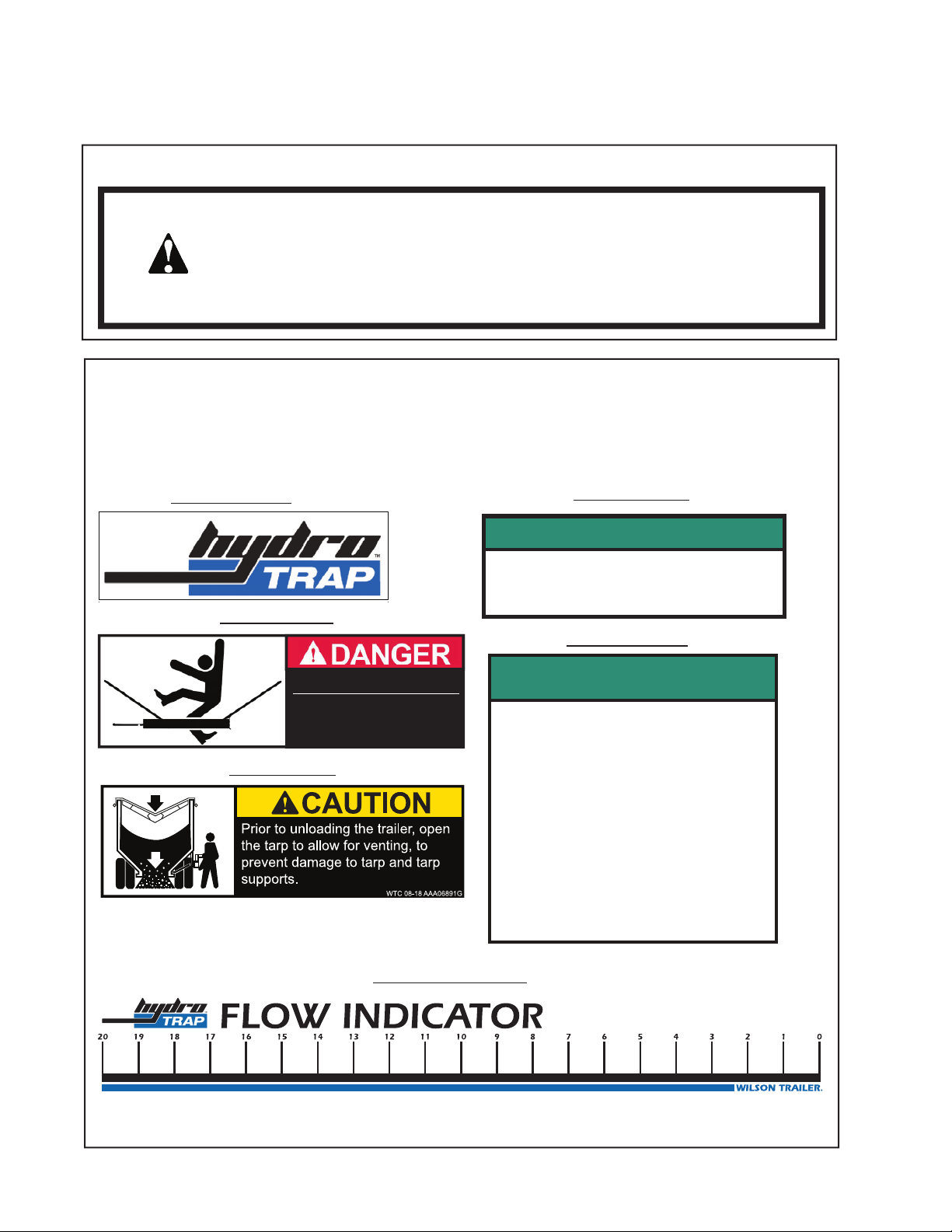
INSPECTION
HYDRO-Trap System Inspection
Perform all inspections in order: No power to trailer; Add 7-way power; Add dual conductor
power.
This inspection assumes the common installs having a Shur-Co 4500 power tarp with a Smart
3 control module, electrical connections are Grote bullets or Deutsch connectors, tractor
has 120 amp kit installed with 120 circuit breaker and disconnect switch, and a Kar-Tech
receiver and KTI hydraulic pump unit installed in the apex of the trailer. Older units may have
connections with crimped bullet connections covered with heat shrink. Several models may
have the receiver and hydraulic power unit mounted over the kingpin.
Inspection Step 1: No Power to Trailer
Tractor power supply and connection to trailer
Disconnect the tractor 7-way and dual conductor cables from the trailer to perform the initial inspection.
Test the 7-way cable voltage output between the center pin auxiliary/ABS power and the ground pin. The
ground pin is the largest of the seven and at the top of the connection.
Test the voltage output of the dual conductor cable. Confirm the 120 amp circuit breaker is installed and is
in the set position. Confirm the main power disconnect switch is on. Both the 120 amp circuit breaker and
disconnect switch must be connected to the positive terminal with the circuit breaker closer to the battery.
Inspect disconnect switch, circuit breaker, connections, plugs, and cables for corrosion.
Front of trailer; outside
Examine the 7-way and dual conductor connections at the front of the trailer for debris buildup, corrosion,
deflected or loose pins, or other damage. Clean corrosion or debris buildup from connectors. Examine the
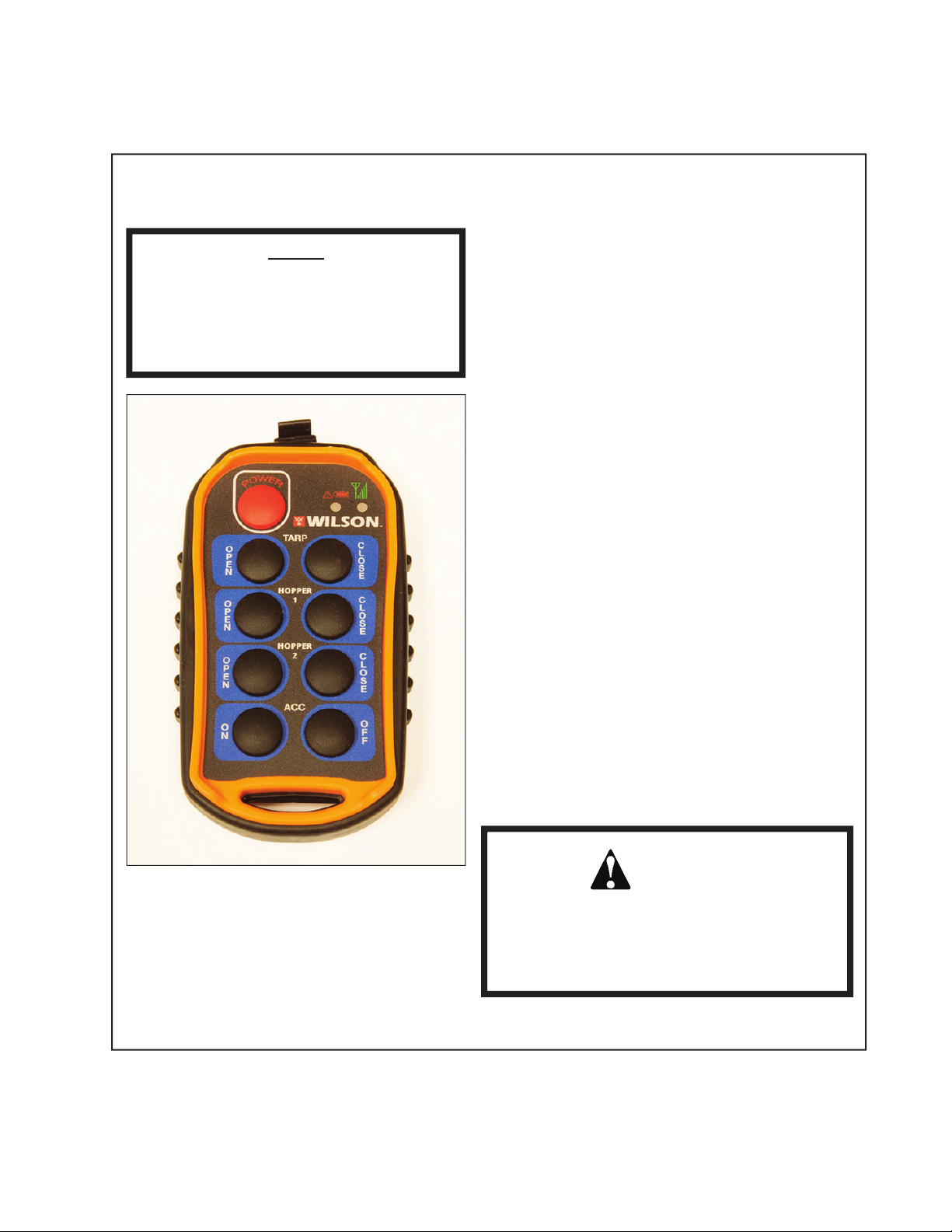
tarp module for damage. Depress open and close button functions for feel of operation.
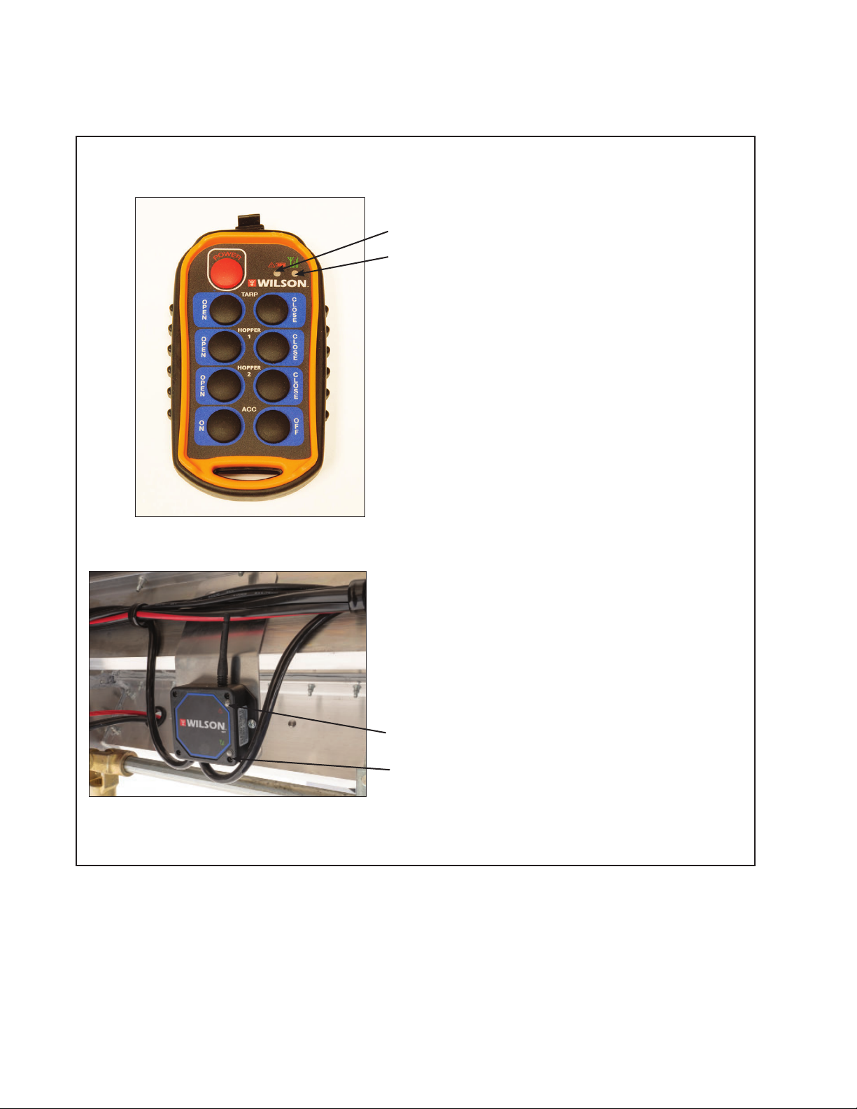
Front of trailer; inside above kingpin
Inspect the inner wall of the front, above the
kingpin. Examine the blue wire power and
white wire ground connections from the
main harness. Inspect the dual conductor
power connections.
Inspect the connections on the tarp module,
dual conductor power system, and control
wire connections. Check the 40 amp fuse
holder for signs of corrosion or debris
buildup and clear drain holes if plugged.
Examine dual conductor cables entering
sidewall of trailer.
REFER TO TROUBLESHOOTING SECTION IF PROBLEMS ARE IDENTIFIED.