7REV B 60706-238
DANGER: FIRE/PERSONAL INJURY
All fuel lines must be installed by a qualied fuel supplier.
The fuel source should be as close as possible to the outdoor operating
location. This will reduce the installation cost of fuel runs. Connect the
fuel supply line to the inlet of the fuel demand regulator on the unit
using a locally approved exible fuel line (see table for recommended
line size). The pressure supplied to the demand regulator must be 4 to
6 ounces or 7 to 11 inches w.c. (water column). The primary regulator
at the fuel supply must be capable of delivering the proper volume of
fuel at this pressure.
Have your local fuel supplier install a protected fuel connection at the
outside operating location. They should also install a lockable fuel shut
off valve at the connection point. An approved exible fuel line must be
installed between the engine generator set and the supply line.
DANGER: FIRE/PERSONAL INJURY
The NG fuel supply line must always be shut off when the engine is not
running. Failure to do so may allow fuel to leak at the unit.
INSTALLING THE FUEL LINE
DANGER: PERSONAL INJURY
Units that are intended to be run unattended MUST have an
electric fuel solenoid installed. This solenoid MUST be wired to
AUTOMATICALLY turn off the fuel whenever the engine stops.
Unit location will determine the size of fuel line the is required to supply
the engine with a constant fuel pressure. Refer to the tables below for
fuel line size and recommended tank size. For distances of 100 feet
and over, a two regulator fuel system is recommended. This system
consisting of a primary 10-15# regulator at the tank and a 6 ounce
secondary regulator installed about 10 feet from the generator. You
need to run a 3/4 inch line or larger from the secondary regulator to the
engine-generator set. When a two (2) regulator fuel system is used, a
fuel line size of 3/8 inch is generally adequate for distances up to 300
feet, The line size from the table below applies to the distance from
the second regulator to the demand regulator. A positive fuel shut-off
device must be installed in the fuel line close to the engine-generator
set. This manual shut-off valve is required by code even if the 12 Volt
fuel solenoid kit is installed. This optional 12 Volt DC valve is available
through your local WINCO dealer and can be used to shut off during
normal periods of operation without having to shut off the manual valve.
The fuel line used to connect the supply line to the demand regulator
must be a locally approved exible fuel line. Products used will vary in
different regions depending on availability and local codes. Consult with
your local fuel supplier to ensure complete compliance with ALL codes.
1. Remove the plastic cover plug from the demand regulator.
2. Connect the ex fuel line to the demand regulator or the
optional solenoid.
DANGER: PERSONAL INJURY
Do NOT use galvanized pipe in the fuel line runs. The galvanized
coating will become eroded and ake off, causing possible obstruction
or damage to the regulator or fuel valve. The obstruction could cause
an inoperative engine or an explosive fuel leak.
Size of pipe required for generators operating on NG gas.
Length of fuel line* Fuel line size
Less than 25 feet 3/4/ in black pipe
25-100 Feet 1 in black pipe
Over 100 feet Not recommended**
*Allow an additional 3 feet for each standard elbow. Do not use ‘street
ells’ (restrictive).
**Consult factory for fuel run over 100 feet.
DANGER: FIRE/PERSONAL INJURY
Be careful when sealing gas joints. Excessive sealing compound can
be drawn into the solenoid, regulator, or carburetor causing an engine
malfunction or dangerous fuel leak.
FUEL CONSUMPTION
(Full Load)
Gasoline 1 gal/hr
Natural Gas 160 ft3/hr 163,200 BTU/hr
FUEL PRESSURE
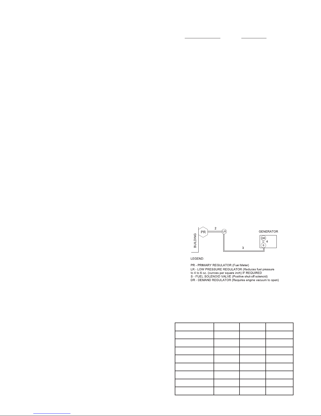
Correct fuel pressure cannot be stressed enough. The most common
cause for inoperative systems is an inadequate or incorrect fuel
pressure. Power and performance of the engine is in direct relation to
the correctness of the fuel system. The following diagram is of a typical
NG installation.
NATURAL GAS
Reference numbers 2 and 3 in the previous diagram are system parts
supplied by the customer. Reference number 4 is the engine-generator
set. The following table is of the fuel pressure reading at each
reference in the system.
Natural Gas Fuel Pressure Table
13240-11 860706-236
Natural Gas
2 3 4
UNIT OFF LINE PSI 7-11 in 7-11 in
4-6 oz 4-6 oz
STARTING LINE PSI 7-11 in 7-11 in
4-6 oz 4-6 oz
NO LOAD LINE PSI 7-11 in 7-11 in
4-6 oz 4-6 oz
FULL LOAD LINE PSI 7-11 in 7-11 in
4-6 oz 4-6 oz
Remember that whichever fuel delivery system or
type of vapor fuel used, the fuel pressure at the
demand regulator installed on the engine generator
must be between 4 and 6 oz. (7-11 inches of water
column). Any lower pressure and the unit will starve
IRUIXHOXQGHUORDG$Q\KLJKHUDQGWKHXQLWZLOOµÀRRG
when attempting to start.
LP TANK SIZING
The tank sizes shown below are the smallest recom-
mended tank sizes based on the outside temperature.
Once above this minimum acceptable size, the size of
L.P. tank used will generally depend on how long you
ZDQWWKHXQLWWRUXQZLWKRXWUH¿OOLQJ.HHSLQPLQG
the colder it gets the slower L.P. will vaporize. This
is the reason for the larger tanks at low temperature.
Minimum sizing is not based on running time.
Temp f. 60 deg 30 deg 0 deg -20 deg
150 gal 250 gal 500 gal 1000 gal
CHANGING FUEL TYPES
These engine generator sets are designed to run
on three different fuels; gasoline, natural gas or LP
vapor. They may be easily changed from one fuel to
another.
FROM GASOLINE TO LP/NG
1. With the engine running turn off the gasoline
fuel valve.
2. Run the engine until it runs out of fuel.
3. Remove the plastic insert from the demand
regulator.
,QVWDOODORFDOO\DSSURYHGÀH[LEOHIXHOOLQH
&RQQHFWWKH/31*YDSRUIXHOOLQHWRWKHÀH[-
ible fuel line. You can’t connect the black iron
pipe dir
$OOWKUHHXQLWVKDYHWZRGLIIHUHQWKRVH¿WWLQJV
on the top of the demand regulator. One is for
LP and one is for Natural Gas. Make sure the
KRVHLVDWWDFKHGWRWKHSURSHU¿WWLQJ6HHWKH
picture below.
7. Turn on the vapor fuel.
8. Start the engine.
9 . Apply the load to the generator.
FROM LP/NG TO GASOLINE
1. With the engine running turn off the LP/NG
fuel supply.
2. Run the engine until it runs out of fuel.
5HPRYHWKHÀH[LEOHIXHOOLQHIURPWKHGHPDQG
regulator.
4. Reinstall the plastic insert in the regulator.
5. Check to be sure the gasoline fuel valve is off.
6. Fill the gasoline fuel tank.
7. Turn on the gasoline fuel valve.
8. Start the engine.
If the optional FUEL SOLENOID kit has been in
stalled on the unit all vapor fuel connection will be
made at the 12 volt gas valve.