WindowMaster WSK 329 User manual

J1
Jumper
Signal-
transmitter
1
5
3
9
7
2
6
4
8
From central
z centrali
Fra central
To the next WSK 3xx
Do nastęnego WSK 3xx
Til næste WSK 3xx
Ifrån central
Till nästa WSK 3xx
Von Zentral
Zum nächsten WSK 3xx
NB;
Signal transmitter
Signalgiver
Signalgivar
Signalgeber
Brzęczyk
Klemme:
1 Indikator "drift” (grøn)
2 Indikator “fejl” (gul)
3 Indikator “NØDÅBN” (rød)
4 Fælles ( - )
5 -
6 Brandtryk “NØDLUK”
7 Brandtryk “NØDÅBN”
8 -
9 -
Jumper J1 må kun sættes i
det sidste eller eneste brandtryk!
Connection:
1 Display "operation" (green)
2 Display "fault” (Yellow)
3 Display “EMERGENCY” (red)
4 Common ( - )
5 -
6 Push button “EMERGENCY CLOSE”
7 Push-button “EMERGENCY-OPEN”
8 -
9 -
Jumper J1 may only be set in the last or
only break glass unit!
WSK 321
Klemme
1 Anzeige "Betrieb" (grün)
2 Anzeige "Störung" (gelb)
3 Anzeige “RWA-Auslösung” (rot)
4 Masse ( - )
5 -
6 Taster “RWA-ZU”
7 Taster "RWA-Auslösung”
8 -
9 -
Jumper J1 nur in der letzten oder
einzigen RWA-Bedienstelle auf beide
Stifte aufstecken !
Anslutning:
1 Indikator ”drift” (grön)
2 Indikator "alarm" (gul)
3 Indikator ”NÖDÖPPNA” (röd)
4 Common ( - )
5 -
6 Brandtryck ”NÖDSTÄNG”
7 Brandtryck ”NÖDÖPPNA”
8 -
9 -
Jumper J1 måste endast sättas
i på det sidsta eller enda brandtrycket!
DK S
DUK
Brandtryk uden akustisk signalgiver
Brandtryck utan akustisk signalgivar
Hauptbediensstelle ohne akust. Signalgeber
Break glass unit without acustic signal transmitter
Ręczny przycisk oddymiania bez alarmu akustycznego
Brandtryk med akustisk signalgiver
Brandtryck med akustisk signalgivar
RWA-Hauptbediensstelle mit akust. Signalgeber
Break glass unit with acustic signal transmitter
Ręczny przycisk oddymiania z alarmem akustycznym
WSK 329
Tilslutningsdiagram
Anslutningsschema
Anschlussplan
Connection diagram
Schemat Połączeń
Połączenie:
1 Dioda “praca” (zielona)
2 Dioda “usterka” (żółta)
3 Dioda “ ALARM” (czerwona)
4 Wspólny (-)
5 -
6 Przycisk “ Reset”
7 Przycisk “ALARM”
8 -
9 -
Zwora J1 musi być założona w
ostatnim, albo jedynym przycisku.
PL
WSK 321+329 install 2212 ©WindowMaster 2005, 2022 ®WindowMaster is a registered trademark used under licence by WindowMaster International A/S
WindowMaster International A/S, Skelstedet 13, DK-2950 Vedbæk
DK +45 4567 0300 info.dk@windowmaster.com
DE +49 (0) 40 87 409 -560 Vertrieb / -484 Technik info.de@windowmaster.com
CH +41 (0) 62 289 22 22 info.ch@windowmaster.com
UK +44 (0) 1536 614 070 info.uk@windowmaster.com
NO +47 902 19 391 info.no@windowmaster.com
IE +353 1903 9455 info.ie@windowmaster.com
US +1 650 360 541 West Coast / +1 215 699 9292 East Coast info.us@windowmaster.com
Other markets +45 4567 0300 info@windowmaster.com www.windowmaster.com

Teknisk data / Tekniska data / Technische Daten / Technical data / Dane techniczne
DK 2
Min ledningsstørrelse: 0,5mm 2
Max ledningsstørrelse: 1,0mm
Max tilladt ledningslængde ved anvendelse af 4x2x0,8:
op til 200.
Kapslingsklasse: IP 40
Klemmer:
1-3 input: 24-30V, max 20mA
4-5: GND 0V
6-8 output: max 30V, max 50mA
9: NC
SE 2
Min ledningsstørrelse: 0,5mm 2
Max ledningsstørrelse: 1,0mm
Max tillåten ledningslängd vid använding av 4x2x0,8:
upp til 200m
Kapslingsklass: IP 40
Anslutning:
1-3 input: 24-30V, max 20mA
4-5: GND 0V
6-8 output: max 30V, max 50mA
9: NC
DE 2
Min Leitungsgrösse: 0,5mm 2
Max Leitungsgrösse: 1,0mm
Max zulässige Leitungslänge bei Verwendung von
4x2x0,8 Kable: bis 200m
Schutzart: IP 40
Klemme:
1-3 Eingang: 24-30V, Max 20mA
4-5: GND 0V
6-8 Ausgang: Max 30V, Max 50mA
9: NC
EN 2
Min cable dimension: 0.5mm 2
Max cable dimension: 1.0mm
Max permissible cable length when using 4x2x0.8:
up to 200m
IP rating: IP 40 Teknisk data
Connection
1-3 Input: 24-30V, max 20mA
4-5: GND 0V
6-8 output: max 30V, max 50mA
9: NC
PL 2
Min. wymiar kabla: 0,5mm 2
Maks. wymiar kabla: 1,0mm
Maks. dopuszczalna długość kabla przy
Maksymalny Maksymalny zastosowaniu 4x2x0,8:
do 200mL
Stopien ochrony: IP 40 Dane techniczne
Połączenie:
1-3 Input: 24-30V , maks 20mA
4-5: GND 0V
6-8 output: maks 30V, maks 50mA
9: NC

LED & Ikon forklaring / Förklaring av lysdioder och ikoner / Erklärung der LEDs
und Symbole / LED- and icon explanation / Objaśnienie diod i ikon
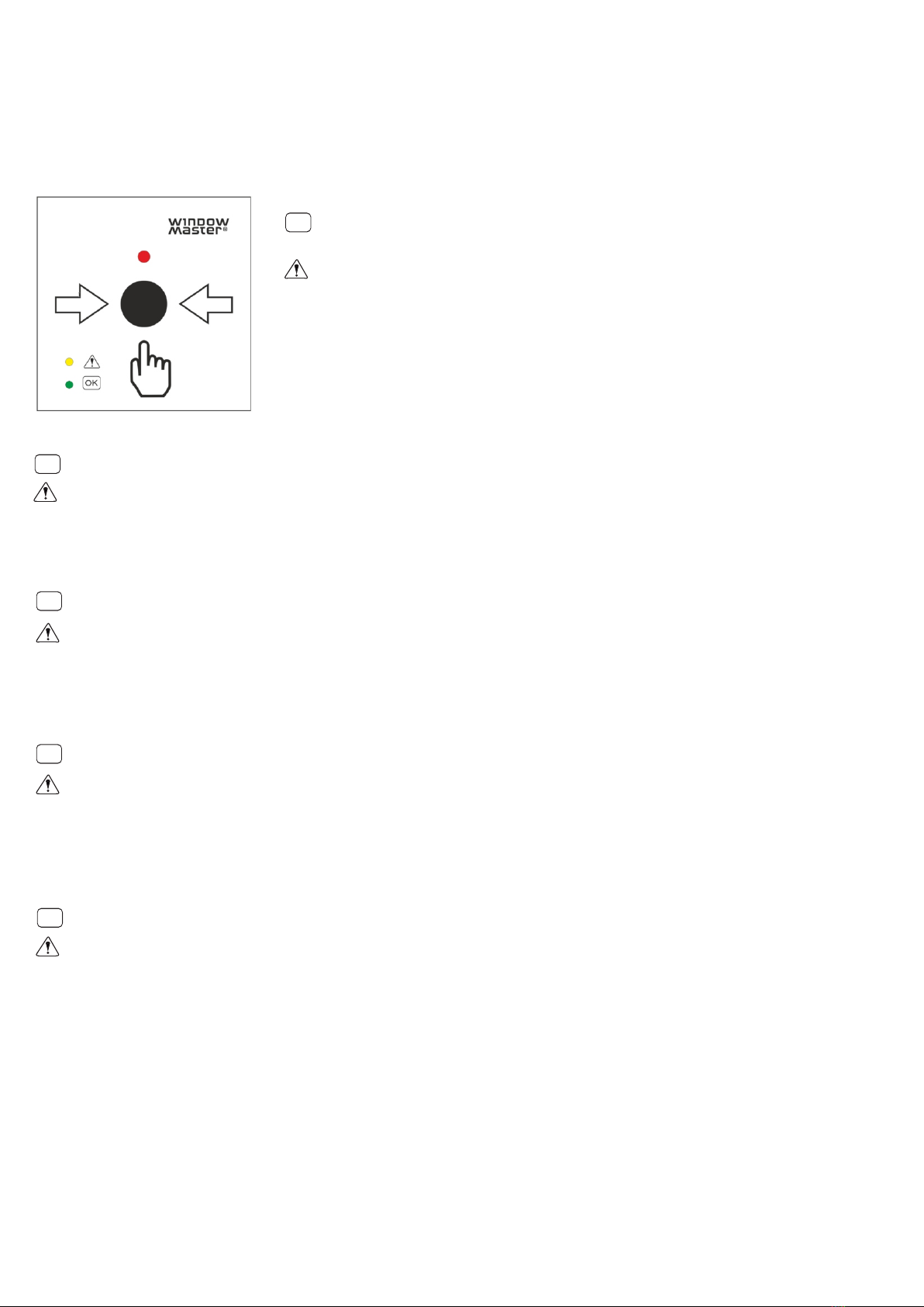
WSK 321 / 329
OK
og grøn Når den grønne LED til venstre for ikonet med OK lyser konstant, er alt okay.
og gul Hvis den gule LED til venstre for ikonet med udråbstegnet lyser, er der fejl i
systemet. Se brandcentralens vejledning for fejlbeskrivelser.
LED
LED
Rød LED Hvis den røde LED over udløserknappen lyser er systemet brandudløst.
Grøn og gul
LED Hvis den grønne lyser konstant, den gule LED blinker og brandtrykket giver akustisk
signal er det serviceindikation. Se brandcentralens vejledning for serviceindikator.
OK
och grön lysdiod När den gröna lysdioden till vänster om OK-ikonen lyser stadigt, allt är okej.
och gula lysdiod Om den gula lysdioden till vänster om ikonen med utropstecknet lyser finns det ett systemfel. Se brandcentralens
bruksanvisning för felbeskrivningar.
Rød LED Om den röda LED ovanför utlösningsknappen lyser är systemet brandutlöst.
Grön och gula lysdiod Om den gröna stadigt, den gula lysdioden blinkar och brandtrycket signalerar akustiskt år det en serviceindikation.
Se brandcentralens bruksanvisning för serviceindikator.
OK
and green LED When the green LED to the left of the OK icon is constantly on, everything is OK..
and yellow LED If the yellow LED to the left of the exclamation mark icon is on, there is a system error. Refer to the smoke
panel manual for error descriptions.
Red LED If the red LED above the trigger button is on, the system has been tripped.
Green and yellow LED If the green LED is constantly on, the yellow LED flash alternately, and the break glass unit is alarming, it is a
maintenance indication. Refer to the smoke panel manual for maintenance indication.
OK
und grüne LED Wenn die grüne LED neben dem OK-Symbol konstant leuchtet, ist alles in Ordnung.
und gelbe LED Wenn die gelbe LED links neben dem Ausrufezeichen-Symbol leuchtet, liegt ein Systemfehler vor.
Fehlerbeschreibungen finden Sie in der Anleitung der RWA-Zentrale.
Rote LED Wenn die rote LED über der Auslösetaste leuchtet, ist das System Feuerausgelöst.
Grüne und gelbe LED Wenn die grüne LED konstant leuchtet, die gelbe LED blinkt und die Bedienstelle akustisches Signal abgibt
handelt es sich um eine Wartungsanzeige. Beschreibung der Wartungsanzeige Finden Sie in der Anleitung
der RWA-Zentrale.
DK
SE
EN
DE
OK
i zielona dioda LED Gdy zielona dioda po lewej stronie ikony OK świeci się stale, wszystko jest w porządku.
i Żółta dioda LED Jeśli żółta dioda LED na lewo od ikony wykrzyknika świeci się, wystąpił błąd systemu. Opisy błędów znajdują
się w instrukcji obsługi centrali sygnalizacji pożaru.
Czerwona dioda LED Jeśli świeci się czerwona dioda LED nad przyciskiem wyzwalającym, system został wyzwolony.
Zielona i żółta dioda LED Jeśli zielona dioda LED świeci się stale, żółta dioda LED miga, a zespół tłuczonego szkła sygnalizuje
akustycznie, jest to wskaźnik konserwacji. Należy zapoznać się z instrukcją obsługi wskaźnika konserwacji
centrali sygnalizacji pożaru.
PL

Montage / Montagen / Montage / Mounting / Montowanie
36mm
125mm
125mm
5 x 9mm
4 x 9mm
95mm
95mm
SMOKE VENT
5 x 9mm
Til forsænket montering i standard indmuringsdåse
För nedsänkt montering i standard inbyggd vägglåda
Zur Befestigung an uP-Dose
For countersunk installation in standard built-in wall box
Do montażu wpuszczanego w standardowej
wbudowanej puszce ściennej
WSK 321 / 329
WSK 321 / 329 monteres indedøre på en væg gennem hullerne i bagpladen. Følg de nationale retningslinjer for afstanden
mellem WSK og gulvniveau.
WSK 321 / 329 monteras inomhus på en vägg genom hålen i bakplattan. Följ nationella riktlinjer för avståndet mellan WSK
och golvnivå.
Die WSK 321 / 329 wird innen an einer Wand durch die Löcher in der Rückwand montiert. Bitte beachten Sie die
nationalen Richtlinien zum Abstand zwischen WSK und Fußboden.
WSK 321 / 329 is to be mounted inside on a wall through the holes in the back plate. Please follow national guidelines
regarding distance between the WSK and floor level.
WSK 321 / 329 należy montować wewnątrz na ścianie poprzez otwory w tylnej płycie. Należy przestrzegać krajowych
wytycznych dotyczących odległości WSK od poziomu podłogi.
Akustisk signal /Akustisk signal / Akustisches Signal / Acoustic signal / Sygnał
akustyczny
Konstant akustisk signal: fejl eller alarm
Gentagne akustisk signal : service timer, se
brandcentralens vejledning
Konstant akustisk signal: fel eller alarm
Uppreprad akustisk signal: servicetimer, se
bruksanvisningen för rökpanelen
Ständiges akustisches Signal: Störung oder Alarm
Wiederholtes akustisches Signal: Wartungsanzeige,
siehe Anleitung der RWA-Zentrale
DK
SE
DE
Constant acoustic signa: fault or alarm
Repeated acoustic signal: service timer, see the instruction
manual for the smoke panel
Stały sygnał akustyczny: usterka lub alarm
Powtarzający się sygnał akustyczny: timer serwisowy, patrz
instrukcja obsługi centrali dymowej
EN
PL
WSK 329
ø5mm
100mm
100mm
SMOKE VENT
ø5mm
WSK 329 WSK 321
This manual suits for next models
1
Popular Transmitter manuals by other brands

M-system
M-system F2TS Installation

Kenwood
Kenwood T-599A user manual

M-system
M-system M1EXS-2 operating manual

Festo
Festo SDAS-MHS Translation of the original instructions

BAYKON
BAYKON TX12 Technical manual

ARTEX AIRCRAFT SUPPLIES
ARTEX AIRCRAFT SUPPLIES B406-4 Operation, installation, and maintenance manual