Winic CW-AR505-8 User manual

Digital Video Recorder
Quick Start Guide

Quick Start Guide of Digital Video Recorder
1
TABLE OF CONTENTS
DVR Installation ..............................................................................................................................................6
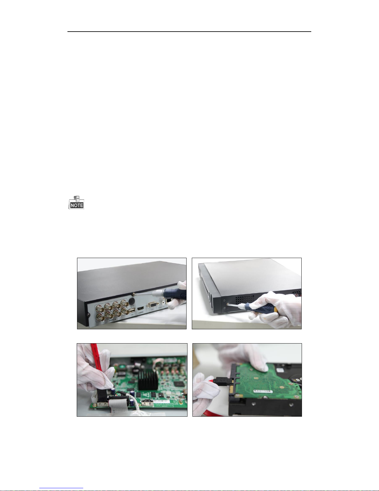
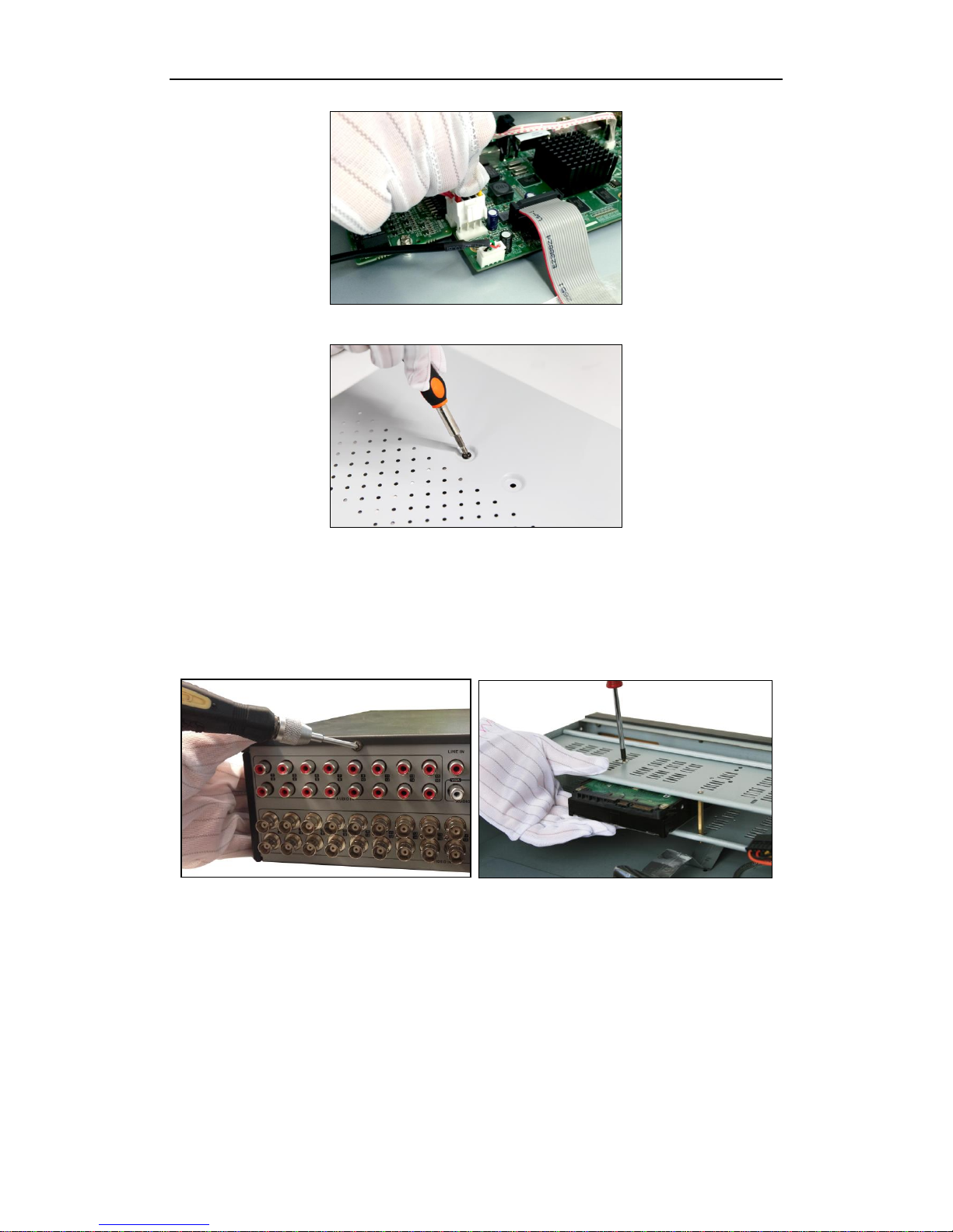
Hard Disk Installation.....................................................................................................................................6
Front Panels....................................................................................................................................................10
Rear Panel ......................................................................................................................................................17
Peripheral Connections .................................................................................................................................18
Wiring of Alarm Input...........................................................................................................................18
Wiring of Alarm Output........................................................................................................................18
Alarm Connection....................................................................................................................................18
RS-485 and Controller Connection..........................................................................................................19
Termination Switch Operation.................................................................................................................20
HDD Storage Calculation Chart...................................................................................................................21
Menu Operation.............................................................................................................................................22
Menu Structure.........................................................................................................................................22
Startup and Shutdown..............................................................................................................................22
Setting the Admin Password ....................................................................................................................23
Login and Logout.....................................................................................................................................24
User Login .......................................................................................................................................24
User Logout .....................................................................................................................................24
Live View.................................................................................................................................................25
Adding IP Cameras ..................................................................................................................................25
PTZ Control.............................................................................................................................................27
Record......................................................................................................................................................28
Instant Recording.............................................................................................................................28
All-day Recording............................................................................................................................29
Playback...................................................................................................................................................29
Backup.....................................................................................................................................................30
Access by Cloud P2P...............................................................................................................................31
Accessing by Web Browser............................................................................................................................32
Logging In................................................................................................................................................32
Live View.................................................................................................................................................33
Recording.................................................................................................................................................34
Playback...................................................................................................................................................35
Log...........................................................................................................................................................36

Quick Start Guide of Digital Video Recorder
2
Quick Start Guide
About this Manual
This Manual is applicable to TVI series DVR.
The Manual includes instructions for using and managing the product. Pictures, charts, images and all other
information hereinafter are for description and explanation only. The information contained in the Manual is
subject to change, without notice, due to firmware updates or other reasons. Please find the latest version in the
company website
Please use this user manual under the guidance of professionals.
Legal Disclaimer
REGARDING TO THE PRODUCT WITH INTERNET ACCESS, THE USE OF PRODUCT SHALL BE
WHOLLY AT YOUR OWN RISKS. OUR COMPANY SHALL NOT TAKE ANY RESPONSIBILITES FOR
ABNORMAL OPERATION, PRIVACY LEAKAGE OR OTHER DAMAGES RESULTING FROM CYBER
ATTACK, HACKER ATTACK, VIRUS INSPECTION, OR OTHER INTERNET SECURITY RISKS;
HOWEVER, OUR COMPANY WILL PROVIDE TIMELY TECHNICAL SUPPORT IF REQUIRED.
SURVEILLANCE LAWS VARY BY JURISDICTION. PLEASE CHECK ALL RELEVANT LAWS IN YOUR
JURISDICTION BEFORE USING THIS PRODUCT IN ORDER TO ENSURE THAT YOUR USE CONFORMS
THE APPLICABLE LAW. OUR COMPANY SHALL NOT BE LIABLE IN THE EVENT THAT THIS
PRODUCT IS USED WITH ILLEGITIMATE PURPOSES.
IN THE EVENT OF ANY CONFLICTS BETWEEN THIS MANUAL AND THE APPLICABLE LAW, THE
LATER PREVAILS.

Quick Start Guide of Digital Video Recorder
3
Regulatory Information
FCC Information
FCC compliance: This equipment has been tested and found to comply with the limits for a Class A digital device,
pursuant to part 15 of the FCC Rules. These limits are designed to provide reasonable protection against harmful
interference when the equipment is operated in a commercial environment. This equipment generates, uses, and
can radiate radio frequency energy and, if not installed and used in accordance with the instruction manual, may
cause harmful interference to radio communications. Operation of this equipment in a residential area is likely to
cause harmful interference in which case the user will be required to correct the interference at his own expense.
FCC Conditions
This device complies with part 15 of the FCC Rules. Operation is subject to the following two conditions:
1. This device may not cause harmful interference.
2. This device must accept any interference received, including interference that may cause undesired operation.
EU Conformity Statement
This product and - if applicable - the supplied accessories too are marked with "CE" and comply
therefore with the applicable harmonized European standards listed under the EMC Directive
2004/108/EC, the RoHS Directive 2011/65/EU.
2012/19/EU (WEEE directive): Products marked with this symbol cannot be disposed of as unsorted
municipal waste in the European Union. For proper recycling, return this product to your local
supplier upon the purchase of equivalent new equipment, or dispose of it at designated collection
points. For more information see: www.recyclethis.info
2006/66/EC (battery directive): This product contains a battery that cannot be disposed of as unsorted
municipal waste in the European Union. See the product documentation for specific battery
information. The battery is marked with this symbol, which may include lettering to indicate
cadmium (Cd), lead (Pb), or mercury (Hg). For proper recycling, return the battery to your supplier or to a
designated collection point. For more information see: www.recyclethis.info
Industry Canada ICES-003 Compliance
This device meets the CAN ICES-3 (A)/NMB-3(A) standards requirements.

Quick Start Guide of Digital Video Recorder
4
Safety Instruction
These instructions are intended to ensure that user can use the product correctly to avoid danger or property loss.
The precaution measure is divided into “Warnings” and “Cautions”
Warnings: Serious injury or death may occur if any of the warnings are neglected.
Cautions: Injury or equipment damage may occur if any of the cautions are neglected.
Warnings
Proper configuration of all passwords and other security settings is the responsibility of the installer
and/or end-user.
In the use of the product, you must be in strict compliance with the electrical safety regulations of the
nation and region. Please refer to technical specifications for detailed information.
Input voltage should meet both the SELV (Safety Extra Low Voltage) and the Limited Power Source
with 100~240 VAC or 12 VDC according to the IEC60950-1 standard. Please refer to technical
specifications for detailed information.
Do not connect several devices to one power adapter as adapter overload may cause over-heating or a
fire hazard.
Please make sure that the plug is firmly connected to the power socket.
If smoke, odor or noise rise from the device, turn off the power at once and unplug the power cable, and
then please contact the service center.
Warnings Follow these
safeguards to prevent serious
injury or death.
Cautions Follow these precautions
to prevent potential injury or
material damage.

Quick Start Guide of Digital Video Recorder
5
Preventive and Cautionary Tips
Before connecting and operating your device, please be advised of the following tips:
•Ensure unit is installed in a well-ventilated, dust-free environment.
•Unit is designed for indoor use only.
•Keep all liquids away from the device.
•Ensure environmental conditions meet factory specifications.
•Ensure unit is properly secured to a rack or shelf. Major shocks or jolts to the unit as a result of dropping it
may cause damage to the sensitive electronics within the unit.
•Use the device in conjunction with an UPS if possible.
•Power down the unit before connecting and disconnecting accessories and peripherals.
•A factory recommended HDD should be used for this device.
•Improper use or replacement of the battery may result in hazard of explosion. Replace with the same or
equivalent type only. Dispose of used batteries according to the instructions provided by the battery
manufacturer.

Quick Start Guide of Digital Video Recorder
6
DVR Installation
During the installation of the DVR:
1. Use brackets for rack mounting.
2. Ensure there is ample room for audio and video cables.
3. When installing cables, ensure that the bend radius of the cables are no less than five times than its diameter.
4. Connect both the alarm and RS-485 cable.
5. Allow at least 2cm (≈0.75-inch) of space between racks mounted devices.
6. Ensure the DVR is grounded.
7. Environmental temperature should be within the range of -10 ºC ~ 55 ºC, 14ºF ~ 131ºF.
8. Environmental humidity should be within the range of 10% ~ 90%.
Hard Disk Installation
Before you start:
Before installing a hard disk drive (HDD), please make sure the power is disconnected from the DVR. A factory
recommended HDD should be used for this installation.
Up to 8 SATA hard disks can be installed on your DVR.
Tools Required: Screwdriver.
As the installation steps of HDD are similar among different models, here we take the steps of some series as
examples.
HDD Installation (A)
Steps:
1. Remove the cover from the DVR by unfastening the screws on the back and side.
2. Connect one end of the data cable to the motherboard of DVR and the other end to the HDD.
3. Connect the power cable to the HDD.

Quick Start Guide of Digital Video Recorder
7
4. Place the HDD on the bottom of the device and then fasten the screws on the bottom to fix the HDD.
5. Re-install the cover of the DVR and fasten screws.
HDD Installation (B)
Steps:
1. Remove the cover from the DVR by unfastening the screws on the back and side.
2. Install the HDD to the HDD rack using the provided screws, and then fasten the
screws to fix the HDD.
3. Connect one end of the data cable to the motherboard of DVR and the other end to the
HDD.
4. Connect the power cable to the HDD.
5. Re-install the cover of the DVR and fasten screws.

Quick Start Guide of Digital Video Recorder
8
HDD Installation (C)
1. Fasten the hard disk mounting handle to the hard disk with screws.
2. Insert the key and turn in clockwise direction to open the panel lock.
3. Press the buttons on the two sides of the front panel to open it.
4. Insert the hard disk along the slot until it is placed into position.

Quick Start Guide of Digital Video Recorder
9
5. Repeat the above steps to install other hard disks onto the DVR. After having finished
the installation of all hard disks, close the front panel and lock it with the key again.

Quick Start Guide of Digital Video Recorder
10
Front Panels
Front Panel 1:
Description of Front Panel
No.
Name
Function Description
1
POWER
Power indicator turns yellow when the power switch on the real
panel is turned on.
STATUS
Status indicator blinks red when data is being read from or written to
HDD.
Tx/Rx
Tx/Rx indictor blinks yellow when network connection is
functioning properly.
2
DIRECTIONS
The DIRECTION buttons are used to navigate between different
fields and items in menus.
In the Playback mode, the Up and Down button is used to speed up
and slow down recorded video. The Left and Right button will select
the next and previous record files.
In Live View mode, these buttons can be used to cycle through
channels.
In PTZ control mode, it can control the movement of the PTZ
camera.
ENTER
The ENTER button is used to confirm selection in any of the menu
modes.
It can also be used to tick checkbox fields.
In Playback mode, it can be used to play or pause the video.
In single-frame Playback mode, pressing the button will advance the
video by a single frame.
3
Menu
Access the main menu interface
4
ESC
Exit and back to the previous menu.
5
IR Receiver
Receiver for IR remote controller.
6
USB Interfaces
Universal Serial Bus (USB) ports for additional devices such as
USB mouse and USB Hard Disk Drive (HDD).

Quick Start Guide of Digital Video Recorder
11
Front Panel 2:
Description of Front Panel
No.
Name
Function Description
1
POWER ON/OFF
Power on/off switch.
2
USB Interface
Connect to USB mouse or USB flash memory.
3
IR Receiver
Receiver for IR remote control. devices.
4
POWER
Power indicator lights in green when DVR is powered up.
READY
Ready indicator is normally green, indicating that the DVR is functioning properly.
STATUS
Indicator turns green when DVR is controlled by an IR remote control with the
address from 1~254;
Indicator turns red when the SHIFT button is used;
Indicator does not light when the DVR is controlled by a keyboard or by the IR
remote control with the address of 255;
Indicator turns green when the DVR is controlled by IR remote control (with the
address from 1~254) and keyboard at the same time , and the SHIFT button is not
used;
Indicator turns orange : (a) when the DVR is controlled by IR remote control (with
the address from 1~254) and keyboard at the same time and the SHIFT button is used
as well; (b) when the DVR is controlled by IR remote control (with the address from
1~254) and the SHIFT button is used.
ALARM
Alarm indicator turns red when a sensor alarm is detected.
HDD
HDD indicator blinks in red when data is being read from or written to HDD.
Tx/Rx
TX/RX indictor blinks in green when network connection is functioning properly.
5
DVD-ROM
Slot for DVD-ROM.
6
DIRECTION
The DIRECTION buttons are used to navigate between different fields and items in
menus.
In Playback mode, the Up and Down button is used to speed up and slow down
recorded video.
In All-day Playback mode, the Left/Right button can be used to select the recorded
video of next/previous day; in Playback by Normal Video Search, the Left/Right
button can be used to select the next/previous recorded file.
In Live View mode, the directional buttons can be used to cycle through channels.
In PTZ control mode, it can control the movement of the PTZ camera.
ENTER
Confirm selection in any of the menu modes. It can also be used to tick checkbox
fields.
In Playback mode, it can be used to play or pause the video.
In Single-frame Playback mode, pressing the ENTER button will advance the video
by a single frame.
In Auto-switch mode, it can be used to stop /start auto switch.
7
SHIFT
Switch of compound keys between the numeric/letter input and functional control.
1/MENU
Enter numeral “1”;
Access the main menu interface.
2ABC/F1
Enter numeral “2”;
Enter letters “ABC”;
The F1 button can be used to select all items on the list;
In PTZ Control mode, the F1 button can be used to zoom out (zoom-) the PTZ
camera;
In live view or playback mode, the F1 button can be used to switch between main
and spot video output.
3DEF/F2
Enter numeral “3”;
Enter letters “DEF”;
In PTZ Control mode, the F1 button can be used to zoom in (zoom+) the PTZ
camera;

Quick Start Guide of Digital Video Recorder
12
The F2 button can be used to cycle through tab pages.
4GHI/ESC
Enter numeral “4”;
Enter letters “GHI”;
Exit and back to the previous menu.
5JKL/EDIT
Enter numeral “5”;
Enter letters “JKL”;
Delete characters before cursor;
Select the checkbox and ON/OFF switch;
Start/stop record clipping in playback.
6MNO/PLAY
Enter numeral “6”;
Enter letters “MNO”;
In Playback mode, it is used for direct access to playback interface.
7PQRS/REC
Enter numeral “7”;
Enter letters “PQRS”;
Manual record, for direct access to manual record interface; manually enable/disable
record.
8TUV/PTZ
Enter numeral “8”;
Enter letters “TUV”;
Access PTZ control interface.
9WXYZ/PREV
Enter numeral “9”;
Enter letters “WXYZ”;
Multi-camera display in live view;
In Playback mode or MenuPlaybackTag playback interface, this button can be
used to delete the selected tag.
0/A
Enter numeral “0”;
Switch between input methods (upper and lowercase alphabet, symbols and numeric
input).
In Playback mode, this button can be used to add the default tag.
8
JOG SHUTTLE
Control
Move the active selection in a menu. The inner ring will move the selection up and
down; the outer ring will move it left and right.
In Playback mode, the inner ring is used to jump 30s forward/backward in video
files. The outer ring can be used to speed up/slow down the video.
In Live View mode, it can be used to cycle through different channels.
In PTZ control mode, in can control the movement of the PTZ camera.
Front Panel3:
Description of Front Panel
No.
Name
Function Description
1
POWER ON/OFF
Power on/off switch.
2
IR Receiver
Receiver for IR remote control.
3
USB
Connect to USB mouse or USB flash memory devices.
4
DVD-R/W
Slot for DVD-R/W.
5
ALARM
Alarm indicator turns red when a sensor alarm is detected.
READY
Ready indicator is normally blue, indicating that the DVR is functioning properly.
STATUS
Indicator turns blue when DVR is controlled by an IR remote.
Indicator turns red when controlled by a keyboard and orange when IR remote and
keyboard is used at the same time.
Indicator does not light when the DVR is controlled by the IR remote control with
the address of 255.

Quick Start Guide of Digital Video Recorder
13
HDD
HDD indicator blinks in red when data is being read from or written to HDD.
Tx/Rx
Tx/Rx indictor blinks in blue when network connection is functioning properly.
GUARD
Indicator turns blue when the device is armed;
Indicator does not light when the device is disarmed;
The arm/disarm state can be initiated by pressing and holding on the ESC button
for more than 3 seconds in live view mode.
6
Channel Status
LED Indicators
The button lights in blue when the corresponding channel is recording; it is red
when the channel is in network transmission status; it is pink when the channel is
recording and transmitting.
7
Alphanumeric
Buttons
Switch to the corresponding channel in Live View or PTZ Control mode.
Input numbers and characters in Edit mode.
Switch between different channels in All-day Playback mode.
8
ESC
Exit and back to the previous menu.
Arm/disarm the DVR in live view mode.
REC/SHOT
Enter the Manual Record interface.
Turn audio on/off in Playback mode;
In PTZ control mode, pressing the REC/SHOT button and a Numeric button will
call a PTZ preset.
PLAY/AUTO
Enter the Playback menu;
Auto scan in the PTZ Control mode.
ZOOM+ Button
In PTZ control mode, the ZOOM+ button is used to zoom in the PTZ camera.
A/FOCUS+
Adjust focus in the PTZ Control mode.
Switch between input methods (upper and lowercase alphabet, symbols and
numeric input).
EDIT/IRIS+
Edit text fields. When editing text fields, it will also function as a Backspace button
to delete the character in front of the cursor.
On checkbox fields, pressing the button will tick the checkbox.
In PTZ Control mode, the button adjusts the iris of the camera.
In Playback mode, it can be used to generate video clips for backup.
MENU/WIPER
Return to the Main menu (after successful login);
Turn off audible key beeper by pressing and holding the button for 5 seconds;
Start wiper (if applicable) in PTZ Control mode.
F1/LIGHT
The F1/LIGHT button when used in a list field will select all items on the list.
In PTZ Control mode, it will turn on/off PTZ light.
F2/AUX
The F2/AUX button is used to cycle through tab pages.
MAIN/SPOT/ZO
OM-
Switch to the control of spot output;
In PTZ Control mode, it can be used to zoom out the PTZ camera.
PREV/FOCUS-
Switch between single screen and multi-screen mode.
In PTZ Control mode, it is used to adjust the focus in conjunction with the
A/FOCUS+ button.
PTZ/IRIS-
Enter the PTZ Control mode.
In PTZ Control mode, it is used to close the iris of the PTZ camera.
9
DIRECTION
The DIRECTION buttons are used to navigate between different fields and items
in menus.
In Playback mode, the Up and Down button is used to speed up and slow down
recorded video.
In All-day Playback mode, the Left/Right button can be used to select the recorded
video of next/previous day; in Playback by Normal Video Search, the Left/Right
button can be used to select the next/previous recorded file.
In Live View mode, the directional buttons can be used to cycle through channels.
In PTZ control mode, it can control the movement of the PTZ camera.
ENTER
Confirm selection in any of the menu modes. It can also be used to tick checkbox
fields.
In Playback mode, it can be used to play or pause the video.
In Single-frame Playback mode, pressing the ENTER button will advance the
video by a single frame.
In Auto-switch mode, it can be used to stop /start auto switch.

Quick Start Guide of Digital Video Recorder
14
10
JOG SHUTTLE
Control
Move the active selection in a menu. The inner ring will move the selection up and
down; the outer ring will move it left and right.
In Playback mode, the inner ring is used to jump 30s forward/backward in video
files. The outer ring can be used to speed up/slow down the video.
In Live View mode, it can be used to cycle through different channels.
In PTZ control mode, in can control the movement of the PTZ camera.
Front Panel4:
Description of Front Panel
No.
Name
Function Description
1
POWER ON/OFF
Power on/off switch.
2
IR Receiver
Receiver for IR remote
3
Status
Indicators
ALARM
Turns red when a sensor alarm is detected.
READY
Ready LED is normally blue, indicating that the device is
functioning properly.
STATUS
Turns blue when device is controlled by an IR remote.
Turns red when controlled by a keyboard and purple when IR
remote and keyboard is used at the same time.
HDD
Flashes red when data is being read from or written to HDD.
MODEM
Reserved for future usage.
TX/RX
Flashes blue when network connection is functioning properly.
GUARD
Guard LED turns blue when the device is in armed status; at this
time, an alarm is enabled when an event is detected.
The LED turns off when the device is unarmed. The arm/disarm
status can be changed by pressing and holding on the ESC
button for more than 3 seconds in live view mode.
4
DVD-R/W
Slot for DVD-R/W.
5
Control
Buttons
DIRECTION
The DIRECTION buttons are used to navigate between different
fields and items in menus.
In the Playback mode, the Up and Down button is used to speed
up and slow down recorded video. The Left and Right button
will select the next and previous record files.
In Live View mode, these buttons can be used to cycle through
channels.
In PTZ control mode, it can control the movement of the PTZ
camera.
ENTER
The ENTER button is used to confirm selection in any of the

Quick Start Guide of Digital Video Recorder
15
No.
Name
Function Description
menu modes.
It can also be used to tick checkbox fields.
In Playback mode, it can be used to play or pause the video.
In single-frame Playback mode, pressing the button will advance
the video by a single frame.
In Auto-switch mode, it can be used to stop /start auto switch.
6
USB Interfaces
Universal Serial Bus (USB) ports for additional devices such as
USB mouse and USB Hard Disk Drive (HDD).
7
Front Panel Lock
You can lock or unlock the panel by the key.
8
Composite
Keys
ESC
Back to the previous menu.
Press for Arming/disarming the device in Live View mode.
REC/SHOT
Enter the Manual Record setting menu.
In PTZ control settings, press the button and then you can call a
PTZ preset by pressing Numeric button.
It is also used to turn audio on/off in the Playback mode.
PLAY/AUTO
The button is used to enter the Playback mode.
It is also used to auto scan in the PTZ Control menu.
ZOOM+
Zoom in the PTZ camera in the PTZ Control setting.
A/FOCUS+
Adjust focus in the PTZ Control menu.
It is also used to switch between input methods (upper and
lowercase alphabet, symbols and numeric input).
EDIT/IRIS+
Edit text fields. When editing text fields, it will also function as
a Backspace button to delete the character in front of the cursor.
On checkbox fields, pressing the button will tick the checkbox.
In PTZ Control mode, the button adjusts the iris of the camera.
In Playback mode, it can be used to generate video clips for
backup.
Enter/exit the folder of USB device and eSATA HDD.
MAIN/SPOT/ZOO
M-
Switch between main and spot output.
In PTZ Control mode, it can be used to zoom out the image.
F1/ LIGHT
Select all items on the list when used in a list field.
In PTZ Control mode, it will turn on/off PTZ light (if
applicable).
In Playback mode, it is used to switch between play and reverse
play.
F2/ AUX
Cycle through tab pages.
In synchronous playback mode, it is used to switch between
channels.
MENU/WIPER
Press the button will help you return to the Main menu (after
successful login).
Press and hold the button for 5 seconds will turn off audible key
beep.
In PTZ Control mode, the MENU/WIPER button will start wiper
(if applicable).
In Playback mode, it is used to show/hide the control interface.
PREV/FOCUS-
Switch between single screen and multi-screen mode.

Quick Start Guide of Digital Video Recorder
16
No.
Name
Function Description
In PTZ Control mode, it is used to adjust the focus in
conjunction with the A/FOCUS+ button.
PTZ/IRIS-
Enter the PTZ Control mode.
In the PTZ Control mode, it is used to adjust the iris of the PTZ
camera.
9
Alphanumeric Buttons
Switch to the corresponding channel in Live view or PTZ
Control mode.
Input numbers and characters in Edit mode.
Switch between different channels in Playback mode.
The light of the button is blue when the corresponding channel is
recording; it is red when the channel is in network transmission
status; it is pink when the channel is recording and transmitting.
10
JOG SHUTTLE Control
Move the active selection in a menu. It will move the selection
up and down.
In Live View mode, it can be used to cycle through different
channels.
In the Playback mode: For NRA00 series, the ring is used to
jump 30s forward/backward in video files.
In PTZ control mode, it can control the movement of the PTZ
camera.
11
SLOW DOWN/SPEED UP
Slow down/speed up in playback mode.

Quick Start Guide of Digital Video Recorder
17
Rear Panel
The rear panel vaires according to different models. Please refer to the actual product. The following figure is for
reference only.
Description of Rear Panel
No.
Item
Description
1
VIDEO IN
BNC interface for TVI and analog video input.
2
VIDEO OUT
BNC connector for video output.
3
AUDIO IN
RCA connector
4
USB Port
Universal Serial Bus (USB) port for additional devices.
5
HDMI
HDMI video output connector.
Some models provide HDMI1 and HDMI2 interfaces.
6
VGA
DB15 connector for VGA output. Display local video
output and menu.
7
AUDIO OUT
RCA connector
8
Network Interface
Connector for network
9
RS-485
Connector for RS-485 devices. T+ and T- pins connect to
R+ and R- pins of PTZ receiver respectively.
KB
D+, D- pin connects to Ta, Tb pin of controller. For
cascading devices, the first DVR’s D+, D- pin should be
connected with the D+, D- pin of the next DVR.
ALARM
Connector for alarm input.
Connector for alarm output.
10
Power Supply
100 ~ 240V AC power supply.
11
Power Switch
Switch for turning on/off the device.
12
GND
Ground
13
LINE IN
BNC connector for audio input.
14
eSATA
Connects external SATA HDD, CD/DVD-RW.
15
RS-232 Interface
Connector for RS-232 devices.

Quick Start Guide of Digital Video Recorder
18
Peripheral Connections
Wiring of Alarm Input
The alarm input is an open/closed relay. To connect the alarm input to the device, use the following diagram.
If the alarm input is not an open/close relay, please connect an external relay between the alarm input and the
device.
Wiring of Alarm Output
To connect to an alarm output (AC or DC load), use the following diagram:
DC Load Connection Diagram AC Load Connection Diagram
For DC load, the jumpers can be used within the limit of 12V/1A safely.
To connect an AC load, jumpers should be left open (you must remove the jumper on the motherboard in the
DVR). Use an external relay for safety (as shown in the figure above).
There are 4 jumpers (JP1, JP2, JP3, and JP4) on the motherboard, each corresponding with one alarm output. By
default, jumpers are connected. To connect an AC load, jumpers should be removed.
Example:
If you connect an AC load to the alarm output 3 of the DVR, then you must remove the JP 3.
Alarm Connection
To connect alarm devices to the DVR:
1. Disconnect pluggable block from the ALARM IN /ALARM OUT terminal block.
2. Press and hold the orange part of the pluggable block; insert signal cables into slots and release the orange part.
Ensure signal cables are in tight.
3. Connect pluggable block back into terminal block.

Quick Start Guide of Digital Video Recorder
19
RS-485 and Controller Connection
Typical Connection A:
To connect PTZ to the DVR:
1. Disconnect pluggable block from the RS-485 terminal block.
2. Press and hold the orange part of the pluggable block; insert signal cables into slots and release the orange
part. Ensure signal cables are in tight.
3. Connect A+ on PTZ to D+ on terminal block and B- on controller to D- on terminal block. Fasten stop
screws.
4. Connect pluggable block back into terminal block.
Typical Connection B:
To connect PTZ to the DVR:
1. Disconnect pluggable block from the RS-485 terminal block.
2. Press and hold the orange part of the pluggable block; insert signal cables into slots and release the orange
part. Ensure signal cables are in tight.
3. Connect A+ on PTZ to T+ on terminal block and B- on controller to T- on terminal block. Fasten stop
screws.
4. Connect pluggable block back into terminal block.
To connect a controller to the DVR:
1. Disconnect pluggable block from the KB terminal block.
2. Press and hold the orange part of the pluggable block; insert signal cables into slots and release the orange
part. Ensure signal cables are in tight.
3. Connect Ta on controller to D+ on terminal block and Tb on controller to D- on terminal block. Fasten stop
Table of contents
Other Winic DVR manuals