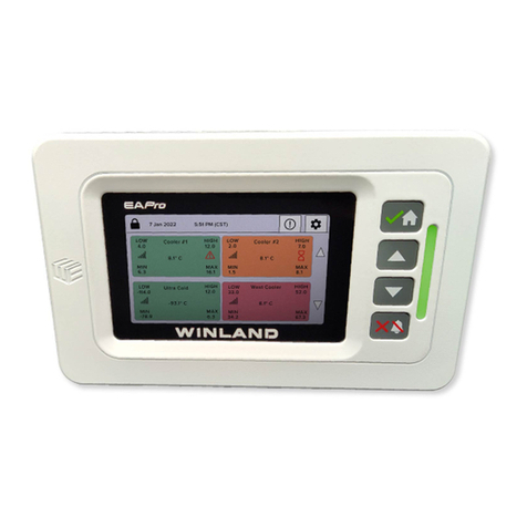
Winland EAPro User manual


Page ii
Winland Electronics, Inc.
Limitations of the Alarm System or Device.
While your alarm system or device is reliable and sophisticated, it does not oer guaranteed
protection against burglary, re or other emergency. Any security product, whether commer-
cial or residential, is subject to compromise or failure-to-warn for a variety of reasons. These
include:
• Individuals may gain access through unprotected openings or have the technical
sophistication to bypass an alarm sensor or disconnect an alarm warning device.
• Monitoring devices will not operate without power. Devices powered by AC will not
work if their AC power supply is o for any reason. If system has battery backup, batteries
that are not maintained can fail to provide the necessary power for devices to function prop-
erly.
• Alarm warning devices such as sirens, bells, and horns may not alert people or
awaken sleepers if they are located on the other side of closed or partly closed doors. If
warning devices are on a dierent level of the residence from the bedrooms, they are less
likely to awaken or alert people inside the bedrooms.
• Telephone lines needed to transmit alarm signals from a premises to a central
monitoring station may be out of service, and are subject to compromise by sophisticated
means of attack.
• Signals sent by wireless transmitters may be blocked or reected by metal before
they reach the alarm receiver. Even if the signal path has been recently checked during a
weekly test, blockage can occur if a metal object is moved into the path.
• Even if the system responds to the emergency as intended and is a monitored alarm
system, the authorities may not respond appropriately.
• This equipment, like other electrical devices, is subject to component failure.
• The most common cause of an alarm system not functioning properly is due to
inadequate maintenance. Your alarm system should be tested weekly to make sure all de-
tection devices are operating properly. Your control panel and keypads should be tested
as well. Installing an alarm system may make you eligible for lower insurance rates, but an
alarm system is not a substitute for insurance. Homeowners, property owners, and renters
should continue to insure their lives and property.

Page iii
Record of Revisions
REV NO. DATE DESCRIPTION
Original May 2022 Initial Issue
Notice
This document will refer to INSIGHT throughout. INSIGHT is a cloud based platform for remote
viewing and management of the EA800-ip device and the EAPro®. INSIGHT is sold separately
and not required to use the EAPro®Gateway. The EAPro® can be used in standalone mode, or
along with INSIGHT in a connected mode. The EAPro®-Gateway monitors the environmental
conditions detected by connected sensors and provides alarm signals when monitored
conditions at any sensor exceeds the user-programmable set points. Winland INSIGHT provides
complete realtime cloudbased visibility of data from EAPro®-Gateway monitored critical
condition environments. The systems detailed and customized response protocols, data logs,
and extreme exibility, provide the fastest resolution of incidents by making the notication
immediately actionable.
NOTE: As of Firmware 22.11.11, the EAPro-Gateway sends notications to INSIGHT, however
INSIGHT does not send out notications to text/emails as this time.

Page iv
Winland Electronics, Inc.
Page Le Blank

Page v
TABLE OF CONTENTS
Foreword 1
Safety Information 1
General Information 3
Overview 3
How to Use This Manual 4
Symbols On the Product or Manual Labeling 5
Relay Block Diagram 5
EAPro®‑Gateway 6
Home Screen 8
Access Control 11
Connections 12
Conguration Parameters 13
Sensors 14
Sensor Programming and Parameter Descriptions 18
Relay Operation 21
Data Logs 21
Installation 22
Installation Tools and Supplies 22
Power Requirements 22
Mount the Rear Plate 23
Connecting Power 23
Initial Start‑Up Procedure 24
Install Wired Sensors 24
Connect Wired Sensors 24
Install Wireless Sensor 25
Program 27
Main Menu 27
Congure System 27
Add Sensor 28
Add User 29
Set System Time and Date Format 29
Set Date and Time 29
Set Lock Mode 30
Select RF Channel 30
Congure Relays 30
Congure Relay State 30
Set Buzzer Triggers 31
Set Light Triggers 31
Operation 32
Acknowledge Alarm 32
Clear Alarm 32
View Sensor Details 32
View Notication Log 32
View Event Log 32
View Sensor Logs 33
View User Logs 33
View About 33

Page vi
Winland Electronics, Inc.
Clear Notication Logs 33
Clear Sensor Logs 33
Export Logs 34
Data Logs 34
Maintenance 35
Edit Sensor 35
Replace Wireless Transmitter 38
Delete Sensor 38
Pause Sensor 39
Test Sensor 39
Edit User 39
Delete User 40
Congure User Mode 40
Sync Users 40
Save System Conguration 40
Edit Network Wi‑Fi 41
Edit Ethernet Settings 41
Update Firmware 42
Reset to Factory Defaults 43
Reboot System 43
Troubleshooting 44
Winland Technical Support 44
Specications 45
Warranty and Service Information 46

Page vii
LIST OF FIGURES
Figure 1: EAPro®‑Gateway 3
Figure 2: EAPro®‑Gateway Block Diagram 6
Figure 3: EAPro®‑Gateway Front 6
Figure 4: Home Screen Sensor Tile 9
Figure 5: Home Screen Tile Examples 9
Figure 6: Connections 13
Figure 7: Wiring Diagram for 4–20mA Sensor – Aux Power Supply 17
Figure 8: Wiring Diagram for 4–20mA Sensor – External Power Supply 17
Figure 9: Wired Sensor Connection: Temperature Probe, WaterBug®, and Dry Contact 25
Figure 10: Wired Sensor Connection: HA‑III+ 25
Figure 11: Wired Sensor Connection: 4–20mA 25
Figure 12: Wireless Sensor MAC Address and ID Location 26
Figure 13: Main Menu 27

Page viii
Winland Electronics, Inc.
Page Le Blank

Page ix
LIST OF TABLES
Table 1: Symbols on Product or Manual Labeling 5
Table 2: EAPro®‑Gateway Parts: Description 7
Table 3: Icons on Touchscreen 7
Table 4: Home Screen Display 8
Table 5: Home Screen Sensor Tile 9
Table 6: Example of Sensor Status on Home Screen Tiles 9
Table 7: User Access Levels 11
Table 8: Lock Setting 12
Table 9: Connector Functions 13
Table 10: Conguration Parameters 13
Table 11: Wired Temperature Probes 14
Table 12: Wired Humidity Sensor 15
Table 13: Wired Water Sensor 15
Table 14: Dry Contact Sensors 15
Table 15: Wireless Temperature Sensor 16
Table 16: Wireless Humidity Sensor 16
Table 17: Wireless MultiFunction Transmitter 16
Table 18: Voltage Selection Matrix for 4–20mA Sensors 17
Table 19: Sensor Programming Parameter Descriptions 18
Table 20: Relay Operation Conditions 21
Table 21: Troubleshooting 44
Table 22: Specications: EAPro®‑Gateway 45
Table 23: Specications: Sensors 46
Table 24: Specications: Accessories 46

Page x
Winland Electronics, Inc.
Page Le Blank

Page 1
Foreword
FOREWORD
Please read this manual and all included material in entirety before unpacking, installing, and
operating your equipment.
The image on the front cover is representative only.
In order to prevent injury or equipment damage, everyone involved in installation, operating
and maintenance of the products described in this manual must be qualied and trained in the
current safety standards that govern their work.
Shock hazard—do not service the product or other electrical products without disconnecting
power and tagging the circuits as out of service.
SAFETY INFORMATION
Warnings on page 27.
WARNING
EAPro®‑Gateway relay outputs are intended only for
use as low voltage, low‑current alarm connections,
and not for direct switching or control of AC‑mains
powered loads. Additionally, local codes may further
dictate or limit the types of loads and associated
wiring to be used with the low‑current Form C relay
outputs used with the EAPro®‑Gateway. Connecting
AC‑mains type circuits to the EAPro®‑Gateway
may result in an electric shock and/or re hazard.
Connect only sensors specied in this manual
to the wired and wireless input connections.
Using sensors not specied in this manual
may damage the EAPro®‑Gateway or cause
improper or unreliable operation.
Do not connect a load to the OUTPUT 1
through OUTPUT 4 relay outputs that exceeds
limitations stated in the Specications section
of this manual. Loads exceeding the specied
limitations may damage the EAPro®‑Gateway,
or result in improper or unreliable operation.
The EAPro®‑Gateway printed circuit board (PCB)
contains electrostatic discharge (ESD) sensitive
devices. To help prevent damage caused by ESD,
observe appropriate ESD handling rules whenever
the PCB in the EAPro®‑Gateway is exposed.
Batteries shall not cause explosion or produce a re
hazard as a result of excessive charge or discharge,
or if a battery is installed with incorrect polarity.
If the equipment is used in a manner not
specied by the manufacturer, the protection
provided by the equipment may be impaired.

Page 2
Winland Electronics, Inc.
Caution on page 28.
CAUTION
Do not connect or disconnect power, sensor, or
alarm wiring while power is applied. Connecting
and disconnecting sensors or alarm wiring
when power is applied to the EAPro®‑Gateway
may damage the EAPro®‑Gateway or result
in improper or unreliable operation.
Connection of unsuitable loads to the
EAPro®‑Gateway power connection may damage
the power supply and EAPro®‑Gateway, or
result in improper or unreliable operation.
Warning on page 46.
WARNING
Clearing the notication logs erases the
information in the notication log. Clearing
the notication log can result in data loss.
Warning on page 64.
WARNING
Resetting to factory defaults erases all
data except the event logs. Resetting to
factory defaults can result in data loss.
Warning on page 64.
WARNING
Per RSS‑Gen, Section 8.4 This device complies
with Industry Canada license‑exempt RSS
standard(s). Operation is subject to the following
two conditions: (1) this device may not cause
interference, and (2) this device must accept
any interference, including interference that may
cause undesired operation of the device.

Page 3
Foreword
To satisfy RF exposure requirements, this device
and its antenna must operate with a separation
distance of at least 20 cm from all persons.
‑‑‑‑‑‑‑‑‑‑‑‑‑‑‑‑
Conformément au CNR‑Gen, section 8.4 Cet
appareil est conforme aux normes RSS d’Industrie
Canada exemptes de licence. Le fonctionnement
est soumis aux deux conditions suivantes : (1)
ce dispositif ne peut pas causer de brouillage, et
(2) ce dispositif doit accepter toute interférence,
y compris les interférences qui peuvent causer
un fonctionnement indésirable de l’appareil.
Pour satisfaire aux exigences d’exposition
aux RF, cet appareil et son antenne doivent
fonctionner avec une distance de séparation
d’au moins 20 cm de toutes les personnes.

Page 4
Winland Electronics, Inc.
GENERAL INFORMATION
OVERVIEW
The EAPro®-Gateway monitors the environmental conditions detected by connected sensors and
provides alarm signals when monitored conditions at any sensor exceeds the user-programmable
set points. The alarm signals are provided via relay outputs that can operate with process
controls, security systems, or other similar automated equipment. The EAPro®-Gateway system
can be congured with wired or wireless sensors (sold separately).
The EAPro®-Gateway provides connection of up to 4 wired and up to 30 wireless sensors.
Setup and program the system using the touchscreen, through the INSIGHT cloudbased
platform (sold separately) or load a CFG le. The touchscreen assists the user during local setup
and displays the measured conditions of monitored environments during operation.
The EAPro®-Gateway can monitor multiple critical environments using multiple sensor inputs.
The system features four output relays to indicate a warning condition exists or a programmed
alarm limit has been exceeded. An auxiliary relay (AUX) alerts when any sensor is in alarm
status.
Using the appropriate Winland sensors (sold separately), the EAPro®-Gateway monitors and
provides warnings and alarms for the following conditions:
• Temperature: from -100 °C to 150 °C (-148 °F to 302 °F)
• Humidity: from 5 to 95% RH (non-condensing)
• Presence of water
• Conditions monitored by any sensor with a 0–5V or a 4–20mA output
The EAPro®-Gateway (see Figure 1) may be mounted to a standard 3-gang electrical enclosure or
directly to wall. The EAPro®wireless sensors are easily mounted to a wall.
Figure 1: EAPro®-Gateway
Note: All product images shown are for illustration purposes only and may not be an exact
representation of the product. Actual product may vary due to product modication.

Page 5
General Information
HOW TO USE THIS MANUAL
When viewed in electronic form, this manual contains internal and external links for quick
navigation to sections and procedures. Click highlighted material to navigate within the
document.
This manual is organized into sections that guide Installation, Program, Operation, and
Maintenance of the EAPro®-Gateway system. Troubleshooting guidelines are also provided as
well as Specications and Warranty and Service Information.
Note: The system can be programmed and operated remotely via INSIGHT (sold separately).
This manual presents programming procedures by showing the sequence of menus and screen
displays to perform the procedure, and wrien instruction to advance through the procedure.
The successive images (left to right) indicate the direction of procedure ow. Navigation includes
using the touchscreen or using soft keys or a combination of both.
Below is an example of a procedure:
1. At the Home Screen, tap the lock icon.
2. Select User (Root is default)
3. Enter 1234 or an assigned PIN (001234 is the same as 1234)
4. Tap Conrm to unlock.
> >
Throughout the manual:
• Buons that appear on the touchscreen is shown like this:
• Quick links internal to the electronic document are shown like this: Home Screen
• Quick links to web pages from the electronic document are shown like this: INSIGHT.
2021
/
01
/
07
5
:
51
:
28
AM
HOME
WARN
1
,
ALARM
1
C
oo
le
r
#
1
8
.
1
°
C
MN MAX
6
.
3 16
.
1
LOW
4
.
0
HH
12
.
0
C
oo
le
r
#
2
8
.
1
°
C
MAXMN
8
.
11
.
5
LOW
2
.
0
HH
7
.
0
W
e
st
C
oo
le
r
55
.
2
°
F
MN MAX
34
.
2 67
.
3
LOW
33
.
0
HH
52
.
0
U
l
tr
a
C
o
ld
-
93
.
1
°
C
MN MAX
-
78
.
9 6
.
3
LOW
-
114
.
0
HH
12
.
0
5
:
5
PM
BACK CONFIRM
LOGIN
USERNAME
PIN
R
oot
2021
/
01
/
07
5
:
51
:
28
AM
HOME
WARN
1
,
ALARM
1
C
oo
le
r
#
1
8
.
1
°
C
MN MAX
6
.
3 16
.
1
LOW
4
.
0
HH
12
.
0
C
oo
le
r
#
2
8
.
1
°
C
MAXMN
8
.
11
.
5
LOW
2
.
0
HH
7
.
0
W
e
st
C
oo
le
r
55
.
2
°
F
MN MAX
34
.
2 67
.
3
LOW
33
.
0
HH
52
.
0
U
l
tr
a
C
o
ld
-
93
.
1
°
C
MN MAX
-
78
.
9 6
.
3
LOW
-
114
.
0
HH
12
.
0
CONFIRM

Page 6
Winland Electronics, Inc.
SYMBOLS ON THE PRODUCT OR MANUAL LABELING
Symbols appearing on the product labeling, packaging, and/or in this manual are shown and
described in Table 1.
Table 1: Symbols on Product or Manual Labeling
SYMBOL DEFINITION
Attention, consult accompanying documents or statements.
Indicates product complies with WEEE Directive 2002/96/EC (Waste from Electrical
and Electronic Equipment) which originated in the European Union.
For product disposal, ensure the following:
Do not dispose of this product as unsorted municipal waste.
Collect this product separately.
Use collection and return systems available.
NULL Indicates product complies with RoHS directive.
N.O. Normally Open (N.O.) relay contact terminal.
C Common relay contact terminal.
N.C. Normally Closed (N.C.) relay contact terminal.
AUX / POWER Combined single pole double throw (SPDT) relay output that activates upon
an alarm from congurable setting. AUX and POWER terms may be used
interchangably.
!

Page 7
General Information
Model: EAPro®‑Gateway
• FCC ID:
V5SEAPGTWY‑0822
• IC:
7635A‑EAPROGTWY
Models: EAPro®‑WMFS,
EAPro®‑WTS, EAPro®‑WHS
• FCC ID:
V5SEAPWLSS‑0822
• IC:
7635A‑EAPROWS
This device complies with part 15 of the FCC Rules. Operation is subject to the
following two conditions:
(1) This device may not cause harmful interference, and
(2) this device must accept any interference received, including interference that
may cause undesired operation.
Per RSS‑Gen, Section 8.4 This device complies with Industry Canada license‑
exempt RSS standard(s). Operation is subject to the following two conditions:
(1) this device may not cause interference, and (2) this device must accept any
interference, including interference that may cause undesired operation of the
device.
To satisfy RF exposure requirements, this device and its antenna must operate with
a separation distance of at least 20 cm from all persons.
Conformément au CNR‑Gen, section 8.4 Cet appareil est conforme aux normes
RSS d’Industrie Canada exemptes de licence. Le fonctionnement est soumis aux
deux conditions suivantes : (1) ce dispositif ne peut pas causer de brouillage, et (2)
ce dispositif doit accepter toute interférence, y compris les interférences qui peuvent
causer un fonctionnement indésirable de l’appareil.
Pour satisfaire aux exigences d’exposition aux RF, cet appareil et son antenne
doivent fonctionner avec une distance de séparation d’au moins 20 cm de toutes les
personnes.
Caution Statement (per CFR 15.21): (Looking to modify to:)
The user manual or instruction manual for an intentional or unintentional radiator
shall caustion the user that changes or moidifcations not expressly approved by
the party responsible for compliance could void the user’s authority to operate the
equipment
Class B Product Compliance Statement (per CFR 15.105(b)): (Can we remove
all of this???)
This equipment has been tested and found to comply with the limits for a Class
B digital device, pursuant to part 15 of the FCC Rules. These limits are designed
to provide reasonable protection against harmful interference in a residential
installation. This equipment generates, uses and can radiate radio frequency
energy and, if not installed and used in accordance with the instruction, may cause
harmful interference to radio communications. However, there is no guarantee that
interference will not occur in a particular installation. If this equipment does cause
harmful interference to radio or television reception, which can be determined
by turning the equipment o and on, the user is encouraged to try to correct the
interference by one or more of the following measures:
• Reorient or relocate the receiving antenna.
• Increase the separation between the equipment and receiver.
• Connect the equipment into an outlet on a circuit dierent from that to which the
receiver is connected.
• Consult the dealer or an experienced radio/TV technician for help.
NULL (Looking to remove all)
The TÜV certication combines electrical safety certication for Canada (SCC),
United States (NRTL), and Europe (EU Directives). This product was voluntarily
tested according to the relevant safety requirements and mentioned properties
pertaining to this certication mark.
The product is in conformity with all applicable requirements for its placing on the
European Union market.

Page 8
Winland Electronics, Inc.
Figure 2 shows a block diagram of the EAPro®-Gateway interfaces and functions. The
EAPro®-Gateway provides (Review) four relays plus an AUX (auxiliary) relay (Review). Program
the four relays to indicate when a programmed alarm limit has been exceeded or a warning
condition exists. The AUX relay provides an output signal for an optional audible alarm or
strobe that is activated whenever any alarm condition exists. The EAPro®-Gateway may also be
part of a larger security system.
Figure 2: EAPro®-Gateway Block Diagram
EAPRO®-GATEWAY
The EAPro®-Gateway features an interactive touchscreen and has four soft keys. A USB port
is located on the right side for quick access. The rear is open for ease of routing wires. Once
installed, unlatch and use hinge to swing down the front for easy maintenance.
Parts and Functions
These topics illustrate the EAPro®-Gateway primary parts and key functions.
Note: All product images shown are for illustration purposes only and may not be an exact
representation of the product. Actual product may vary due to product modications.
Figure 3: EAPro®-Gateway Front
Figure 3 shows the touchscreen and entry keys. The key functions are described in Table 2.
Wired Sensor #1
Wired Sensor #2
Wired Sensor #3
Wired Sensor #4
Wireless Sensor #1
Wireless Sensor #2
Wireless Sensor #30
RF Transceiver
Analog Front End
Relay
Mapping
to
Sensor
Alarms
&
Warnings
(MCU)
Relay #1
(Form C, 1A Contact)
Relay #2
(Form C, 1A Contact)
Relay #3
(Form C, 1A Contact)
Relay #4
(Form C, 1A Contact)
Relay #5
(Form C, 3A Contact)
Output 1
Output 2
Output 3
Output 4
Output 5
EAPro Gateway
Cover Hinges
Touchscreen
Display
Arrow
Keys
Accept/Home
Key
Cancel/Silence
Key
USB

Page 9
General Information
Table 2: EAPro®-Gateway Parts: Description
Part Description/Function
Touchscreen Display The touchscreen displays all the information needed for operation, such as the
Home Screen with sensor status, navigation menus, and the date and time. The
touchscreen provides menubased graphical user interface (GUI) tap navigation to all
of the features and local data.
Accept/Home Key The Accept/Home key provides two functions when pressed: it accepts the currently
entered selection or it displays the Home Screen.
If the selection is a menu item, the selected item is accessed. If the current selection
is an entered value, pressing the key accepts the entered value.
If there is no selection made, pressing the key displays the Home Screen.
Up Arrow Key The up arrow key provides the scroll up function.
Down Arrow Key The down arrow key provides the scroll down function.
Cancel/Silence Key The Cancel/Silence key provides two functions when pressed: it cancels the current
selection, or it temporarily silences alarms and stops light from ashing.
If the selection is a value, the value is cleared.
If there is no selection made, press and hold for 3 seconds the key will temporarily
silence local audible alarms and deactivates a ashing light for ten minutes. If a new
alarm originating from a dierent sensor occurs within this 10‑minute period, the
audible alarm and ashing lights are reactivated, and require another key press and
hold of 3 seconds to silence the audible alarm and deactivate the ashing light.
Note: Pressing the Cancel/Silence key does NOT reset the relay.
USB Port See Connections.
Rear Mounting Plate The rear mounting plate is connected with a hinge. The EAPro®‑Gateway may be
attached to a standard 3gang electrical enclosure or mounted directly to a wall.
Power Input See Connections.
Aux Power Output See Connections.
Relay Inputs See Connections.
Relay Outputs See Connections.
Jumpers See Connections.
Touchscreen Display
The EAPro®-Gateway features a menu based graphical user interface (GUI) on a touchscreen
display. Tap icons (see Table 3) to navigate the touchscreen display or press soft keys to navigate
up or down.
Icons on Touchscreen
Icons on the touchscreen indicate status and provide operational conditions. See Table 3.

Page 10
Winland Electronics, Inc.
Table 3: Icons on Touchscreen
SYMBOL NAME DEFINITION
Lock The touchscreen is locked when this displays in the upper left corner
of the touchscreen. Tap icon to go to Login Screen.
Unlock The touchscreen is unlocked when this displays in the upper left
corner of the touchscreen. Tap icon to lock touchscreen.
Home Tap the home icon to return to the Home Screen.
Battery The battery icon indicates the wireless sensor has a low battery.
Information The information icon is a quick key to access the Data Logs.
Alarm The alarm icon displays during active alarm conditions.
Signal strength The signal strength icon indicates the strength of the wireless
connection. A greater number of bars indicates a stronger
connection. The recommended connection is a strength of four or
ve bars. “Err” will display in sensor reading if signal strength is zero
bars.
De‑active The de‑active toggle indicates the option is deactivated.
Active The active toggle indicates the option is activated.
Check/Accept The Check/Accept icon is on the Accept/Home key.
TimeDelay Warning The warning icon indicates the sensor is in active timedelay for a
warning. The warning state is active and the delay timer is counting
down. An alarm state will occur if the warning is not cleared before
the timer runs out.
TimeDelay Alarm The hourglass icon indicates the sensor is in active timedelay for
an alarm. The alarm state is active and the delay timer is counting
down. An alarm state will occur if the condition is not cleared before
the timer runs out.
Latched Relay Key The key icon indicates the relay is latched.
Gear The gear icon is a quick key to access the Main Menu.
Stop/Cancel The stop or cancel icon stops a current function.
HOME SCREEN
The Home Screen displays operation information including, lock status, date and time, and
sensor status data for four sensors. Tap the “home” icon from any screen to quickly navigate
to the home screen. The Home Screen also has quick access buons to Notication Log and the
Main Menu.
HOME SCREEN HOME SCREEN SECTIONS
Other manuals for EAPro
1
Table of contents
Other Winland Gateway manuals
Popular Gateway manuals by other brands

Dialogic
Dialogic 2000 Series Installation and configuration note

AudioCodes
AudioCodes Mediant 1000B quick guide

ZyXEL Communications
ZyXEL Communications ZyXEL Prestige 310 user guide

Yeastar Technology
Yeastar Technology NeoGate TA1600 user manual

NetSHIELD
NetSHIELD Branch PRO user guide

ETC
ETC Response Mk2 One-Port Setup guide

Helmholz
Helmholz WALL IE Compact quick start guide

Fortress Power
Fortress Power Guardian Installation and operation manual

Rath
Rath 2100-GSM4 Data Sheet / Manual

Ingics
Ingics iGS03W user manual

OBSIDIAN CONTROL SYSTEMS
OBSIDIAN CONTROL SYSTEMS NETRON EP2 installation guide

Netbiter
Netbiter easyconnect ec350 installation guide