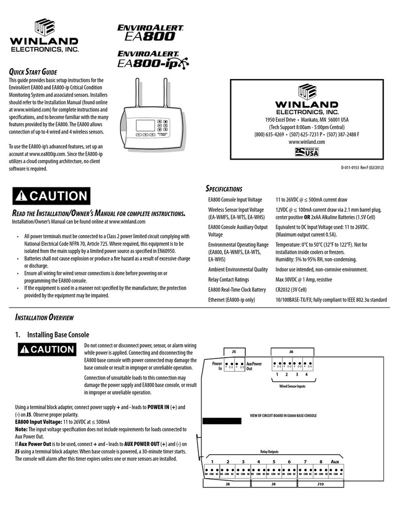
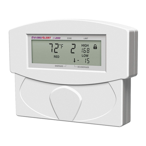
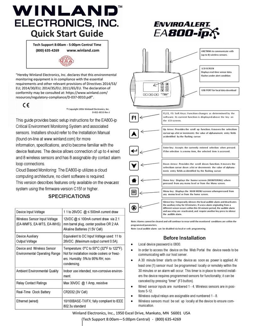
Winland EnviroAlert EA800-ip Installation instructions

D-011-0152
Electronic Multi-Zone Environmental Alarm System
Installation/Owner’s Manual

Limitations of the Alarm System or Device
While your alarm system or device is reliable and sophisticated, it does not offer guaranteed protection against
burglary, fire or other emergency. Any security product, whether commercial or residential, is subject to
compromise or failure-to-warn for a variety of reasons. These include:
•Individuals may gain access through unprotected openings or have the technical sophistication to
bypass an alarm sensor or disconnect an alarm warning device.
•Monitoring devices will not operate without power. Devices powered by AC will not work if their AC
power supply is off for any reason. If system has battery backup, batteries that are not maintained can
fail to provide the necessary power for devices to function properly.
•Alarm warning devices such as sirens, bells, and horns may not alert people or awaken sleepers if they
are located on the other side of closed or partly closed doors. If warning devices are on a different level
of the residence from the bedrooms, they are less likely to awaken or alert people inside the bedrooms.
•Telephone lines needed to transmit alarm signals from a premises to a central monitoring station may
be out of service, and are subject to compromise by sophisticated means of attack.
•Signals sent by wireless transmitters may be blocked or reflected by metal before they reach the alarm
receiver. Even if the signal path has been recently checked during a weekly test, blockage can occur if
a metal object is moved into the path.
•Even if the system responds to the emergency as intended and is a monitored alarm system, the
authorities may not respond appropriately.
•This equipment, like other electrical devices, is subject to component failure.
•The most common cause of an alarm system not functioning properly is due to inadequate
maintenance. Your alarm system should be tested weekly to make sure all detection devices are
operating properly. Your control panel and keypads should be tested as well.
Installing an alarm system may make you eligible for lower insurance rates, but an alarm system is not a substitute
for insurance. Homeowners, property owners, and renters should continue to insure their lives and property.

D-011-0152 3
Table of Contents
General Information............................................................................................................................... 5
Overview............................................................................................................................................ 5
How to Use This Manual.................................................................................................................... 6
Block Diagrams.................................................................................................................................. 7
Symbols on the Product or Manual Labeling ..................................................................................... 8
Monitoring Screens............................................................................................................................ 9
Keys................................................................................................................................................. 10
Console Connections....................................................................................................................... 11
Access Control and Passwords ....................................................................................................... 13
System Configuration Parameters................................................................................................... 13
Sensors............................................................................................................................................ 15
Temperature Sensors ................................................................................................................ 15
Humidity Sensors....................................................................................................................... 16
4-20mA Sensors ........................................................................................................................ 16
Theory of Operation ....................................................................................................... 16
Power Supply / Sensor Voltage Selection...................................................................... 17
Water Sensors ........................................................................................................................... 18
Multi-Function Sensors .............................................................................................................. 18
Dry Contact Sensors.................................................................................................................. 18
Sensor Parameter Descriptions ................................................................................................. 19
Relay Operation............................................................................................................................... 21
Installation............................................................................................................................................ 22
Tools and Supplies Required........................................................................................................... 22
Power Requirements ....................................................................................................................... 22
Mounting the EA800-ip Rear Plate .................................................................................................22
Install the Wired Sensors................................................................................................................. 23
EA800-ip Console Power Connections............................................................................................ 23
Install the Wireless Sensors............................................................................................................. 23
Connecting Wired Sensors .............................................................................................................. 25
Programming ................................................................................................................................... 27
Accessing the MAIN MENU for Programming ........................................................................... 28
Configuring System Parameter Settings.................................................................................... 28
Adding Wireless Sensors................................................................................................................. 29
Verify Wireless Signal Strength ................................................................................................. 31
Adding Wired Sensors ..................................................................................................................... 32
Adding a Wired Sensor .............................................................................................................. 32
Adding a 4-20mA Sensor........................................................................................................... 33
Configuring the Relays..................................................................................................................... 34
Operation.............................................................................................................................................. 35
Monitoring Environmental Conditions .............................................................................................. 35
Viewing Sensor Settings.................................................................................................................. 36
Viewing Active Alarms ..................................................................................................................... 36
Viewing the Alarm Log..................................................................................................................... 37
Viewing the Event Log ..................................................................................................................... 38
Viewing the Sensor Log................................................................................................................... 39
Viewing Firmware Information ......................................................................................................... 39
Viewing RF Information.................................................................................................................... 40

4D-011-0152
Maintenance ......................................................................................................................................... 41
Locking and Unlocking the EA800-ip ................................................................................................... 41
Pausing Monitoring and Cancelling Pause ...................................................................................... 42
Replacing a Sensor.......................................................................................................................... 43
Editing Sensor Parameters .............................................................................................................. 44
Deleting a Sensor ............................................................................................................................ 45
Changing the Date Format............................................................................................................... 45
Changing the Time Format .............................................................................................................. 46
Changing the Date or Time Setting.................................................................................................. 46
Changing Sensor Data Collection Frequency.................................................................................. 46
Changing the Buzzer Setting ........................................................................................................... 47
Changing the Password................................................................................................................... 48
Clearing the Alarm Log .................................................................................................................... 49
Clearing the Sensor Log .................................................................................................................. 49
Updating the Firmware..................................................................................................................... 50
Saving Configuration Settings.......................................................................................................... 51
Loading Configuration Settings........................................................................................................ 52
Exporting the Stored Logs ............................................................................................................... 53
Exported Alarm Data.................................................................................................................. 53
Exported Event Data.................................................................................................................. 54
Exported Sensor Data................................................................................................................ 54
Troubleshooting................................................................................................................................... 55
Verifying RF Signal Strength............................................................................................................ 56
Viewing Signal Strength for a Wireless Sensor.......................................................................... 56
Specifications....................................................................................................................................... 57
Console and Sensor Specifications ................................................................................................. 57
Accessories...................................................................................................................................... 58
Warranty and Service Information ..................................................................................................... 61

D-011-0152 5
General Information
Overview
The EnviroAlert® EA800-ip Multi-Zone Environmental Alarm System monitors the environmental conditions detected
by the sensors connected to the console, and provides alarm signals when monitored conditions at any of the
sensors exceed the user-programmable HIGH LIMIT orLOW LIMIT set points. The alarm signals are provided via
relay outputs that can operate with process controls, security systems, or other similar automated equipment. The
EA800-ip Alarm System can be configured with wired or optional wireless sensors (sold separately).
The EA800-ip allows connection of up to 4wired and up to 8 wireless sensors.
Setup and programming is done using the front panel keys and the liquid crystal display (LCD) on the console.The
display assists the user during setup, and shows measured conditions for the monitored environment during
operation.
The EA800-ip can monitor multiple critical environments using multiple sensor inputs. Each sensor input has a
corresponding relay output.
Using the appropriate accessory sensors (sold separately), the EA800-ip Alarm System monitors and provides
alarms for the following conditions:
■Temperature: from -80° C to 150° C (-112° F to 302° F)
■Humidity: from 5 to 95% RH (non-condensing)
■Presence of water
■Any sensor with a 4-20mA interface
The EA800-ip console may be mounted directly to a standard 3-gang electrical enclosure or to walls. The wireless
sensors are easily mounted to the wall. Figure 1 shows the console and a wireless sensor.
Figure 1 EnviroAlert EA800-ip Console and Optional Wireless Sensor

6D-011-0152
How to Use This Manual
This manual is organized into sections that guide you through the installation process, then describe how to use
the EA800-ip and change its programmed settings if necessary. Some troubleshooting guidelines are provided.
The manual presents EA800-ip programming procedures by showing you the sequence of menus and screens you
will see as you perform the procedure, and the keys to press to advance to the next screen. The example below is
the procedure for unlocking the EA800-ip console to allow programming.
The arrows on the drawing indicate the direction of procedure flow.
In all procedures, use the keys to select menu options and to increase/decrease alphanumeric values for
programming options. Use the PREV and NEXT soft keys (F2 and F3) to move the cursor to the next digit when
entering numeric data.
The functions of the soft keys change and are defined on the screen in the area above each key. If no
text is shown above a soft key, it means the key performs no function on the current screen.
“Keys” on page 10 describes the functions of each key on the console.
Throughout the manual, text that appears on the EA800-ip console screens is shown like this: MONITORING
Key names are shown in text like this: F1
The current menu selection is highlighted on the screen by arrows on either side of
the selection, as shown in the example at right. On this MAIN MENU screen, the
current selection is Sensors.
Use the or keys to move the highlight to the desired menu item, then
press to make the selection.
Enter:
0800
F1
Step 1: Press the
F1 soft key.
Step 2: The UNLOCK screen
is displayed. Enter your
password using the arrow
keys.
Step 3: Press the
ENTER key
F1 can be pressed at this time
to lock the unit.
F1 F2 F3

General Information
D-011-0152 7
Block Diagrams
Figure 2 shows a block diagram of the console interfaces and functions. The EA800-ip provides eight relays for
indicating when a programmed alarm limit has been exceeded or a warning condition exists. An additional AUX
(Auxiliary) Output relay provides an output signal to an optional audible alarm or strobe that is activated whenever
an alarm condition exists.
Figure 2 EA800 Environmental Alarm System Block Diagram
The EA800 can be made part of a larger security system as shown in Figure 3. In a security system there may be
more than one EA800 installed along with other components such as the Winland EA200 or EA400 multi-zone
environmental alarm systems.
Figure 3 Facility Security System Block Diagram - Example
Sensor 5
Sensor 6
Sensor 7
Sensor 8
Wireless Sensors
Relay 1 Output 1
Output 2
Relay 2
Output 3
Relay 3
Output 4
Relay 4
Output 5
Relay 5
Output 6
Relay 6
Output 7
Relay 7
Output 8
Relay 8
EA800 Console
Aux Output
RF Receiver
Sensor 1
Sensor 2
Sensor 3
Sensor 4
System Control
Relay 9
Relay 1 coil control logic
Relay 2 coil control logic
Relay 3 coil control logic
Relay 4 coil control logic
Relay assignment
and coil control logic
Wired Sensors
Alarm Panel
From other
EA800, EA400, and EA200
Environmental Alarm Systems
Sensor 5
Sensor 6
Sensor 7
Sensor 8
Wireless Sensors
Relay 1 Output 1
Output 2
Relay 2
Output 3
Relay 3
Output 4
Relay 4
Output 5
Relay 5
Output 6
Relay 6
Output 7
Relay 7
Output 8
Relay 8
EA800 Console
Aux Output
RF Receiver
Sensor 1
Sensor 2
Sensor 3
Sensor 4
System Control
Relay 9
Relay 1 coil control logic
Relay 2 coil control logic
Relay 3 coil control logic
Relay 4 coil control logic
Relay assignment
and coil control logic
Wired Sensors
Wired Sensors

8D-011-0152
Symbols on the Product or Manual Labeling
Symbols appearing on the product labeling, packaging, and/or in this manual are shown and described in Table 1.
Table 1 Symbols on Product or Manual
Symbol Definition
Attention, consult accompanying documents or statements.
For product disposal, ensure the following:
• Do not dispose of this product as unsorted municipal waste.
• Collect this product separately.
• Use collection and return systems available to you.
Indicates product complies with RoHS-WEEE directive.
N.O. Normally Open (N.O.) relay contact terminal
N.C. Normally Closed (N.C.) relay contact terminal
CCommon relay contact terminal
AUX Combined single pole double throw (SPDT) relay output that activates upon an alarm
from any of the sensors.
Model: EA800-ip
• FCC ID:
V5SEA800-031108
• IC: 7635A-EA800
Models: EA-WMFS,
EA-WTS, EA-WHS
• FCC ID:
V5SEA-WS-031108
• IC: 7635A-EAWS
This device complies with part 15 of the FCC Rules. Operation is subject to the follow-
ing two conditions: (1) This device may not cause harmful interference, and (2) this
device must accept any interference received, including interference that may cause
undesired operation.
Caution Statement (per CFR 15.21):
Changes or modifications not expressly approved by the party responsible for compli-
ance could void the user’s authority to operate the equipment.
Class B Product Compliance Statement (per CFR 15.105(b)):
NOTE: This equipment has been tested and found to comply with the limits for a
Class B digital device, pursuant to part 15 of the FCC Rules. These limits are
designed to provide reasonable protection against harmful interference in a residential
installation. This equipment generates, uses and can radiate radio frequency energy
and, if not installed and used in accordance with the instruction, may cause harmful
interference to radio communications. However, there is no guarantee that interfer-
ence will not occur in a particular installation. If this equipment does cause harmful
interference to radio or television reception, which can be determined by turning the
equipment off and on, the user is encouraged to try to correct the interference by one
or more of the following measures:
• Reorient or relocate the receiving antenna.
• Increase the separation between the equipment and receiver
• Connect the equipment into an outlet on a circuit different from that to which the
receiver is connected.
• Consult the dealer or an experienced radio/TV technician for help.
The TÜV certification combines electrical safety certification for Canada (SCC), United
States (NRTL), and Europe (EU Directives). This product was voluntarily tested
according to the relevant safety requirements and mentioned properties pertaining to
this certification mark.
The product is in conformity with all applicable requirements for its placing on the
European Union market.

General Information
D-011-0152 9
Monitoring Screens
The EA800-ip user interface is menu-based. During normal system monitoring, one of the following three screens is
displayed depending on the current state of the programmed sensors:
The MONITORING (home) screen is displayed
when there are no active alarms. The screen lists
all programmed sensors connected to the console
and their current reading or state.
The MONITORING screen displays pending alarms
in inverse as shown in the example at right
(76% exceeds the humidity limit for Sensor 5, so it
is shown as light text on black). Pending alarms
indicate that the programmed limits for the sensor
have been exceeded, but the sensor’s pro-
grammed delay time has not yet elapsed. If the
monitored conditions continue to exceed the pro-
grammed limits for longer than the programmed
delay period, the pending alarm will become an
active alarm.
The ACTIVE ALARMS screen is shown when one or
more sensors are in an active alarm or warning
state. If more than one alarm is active, each will
be listed on the screen. In the example shown, a
Cooler #1 alarm is occurring.

10 D-011-0152
Keys
Keys
Figure 4 shows the console display and entry keys. The keys are described in Table 2.
Figure 4EA800-ip Console Keys
Table 2 Key Functions
Key Function
F1 This key's function changes as determined by the software. Its current function is
displayed immediately above the key on the display.
F2 This key's function changes as determined by the software. Its current function is
displayed immediately above the key on the display.
F3 This key's function changes as determined by the software. Its current function is
displayed immediately above the key on the display.
Up Arrow: This key provides the scroll up function. It moves the selection cursor up
a list or increments the value of alphanumeric entry fields as identified by the flash-
ing cursor. The values provided are dependent on the currently active field. For
example, the available selections may be a + or - sign, numbers, or alphanumeric
characters and special characters.
Down Arrow: This key provides the scroll down function. It moves the selection
cursor down a list or decrements the value of alphanumeric entry fields as identified
by the flashing cursor. The values provided are dependent on the currently active
field. For example, the available selections may be a + or - sign, numbers, or alpha-
numeric characters and special characters.
ENTER key. This key accepts the currently entered selection when pressed. If the
selection is a menu item, the selected item is accessed. If the current selection is an
entered value, pressing the ENTER key accepts the entered value.
HOME key. This key displays the home screen (MONITORING) when pressed.

General Information
D-011-0152 11
Console Connections
Figure 5 shows the EA800-ip console's connections and Table 3 describes the functions of each connection.
Note: The console has four wired sensor inputs and four wireless RF sensor inputs.
Figure 5EA800LS Console Connections
MENU key: Displays the MAIN MENU screen when pressed from any menu level or
from the home screen.
SILENCE key: Alarms cannot be cleared and will continue to recur until the moni-
tored conditions detected by the sensors are within the programmed parameters.
Pressing the SILENCE key temporarily silences the local audible alarm and deacti-
vates the auxiliary relay for 10 minutes.
If a new alarm originating from a different sensor occurs within this 10-minute
period, the audible alarm and aux relay are reactivated, and require another key
press to silence the audible alarm.
Table 2 Key Functions — continued
Power
In
Aux
Power
Out
J6
J5
Input 1 Input 2 Input 3 Input 4
J13 J14
J2
J10J8 J9
Output 1 Output 2 Output 3 Output 4 Output 5 Output 6 Output 7 Output 8 Aux
NO COM NC NO COM NC NO COM NC NO COM NC NO COM NC NO COM NC NO COM NC NO COM NC NO COM NC
Wired Inputs

12 D-011-0152
Console Connections
Table 3 EA800-ip Console Connector Functions
Connector Designation Function
J2 USB USB Type A connection used to program firmware, export logs, and export
and import configuration files.
J5 Power In 11-26 VDC input power connection for EA800-ip console (from accessory power
supply or alarm panel).
CAUTION
!
CAUTION
Observe (+) and (-) polarity markings on circuit board. EA800-ip can
be damaged if power polarity is reversed.
Aux Power Out 11-26 VDC power out connection for EA800-ip accessories requiring power
(such as HA-III+ Humid Alert). This output voltage equals that of Power In and
is current-limited to a maximum of 500 mA.
CAUTION
!
CAUTION
Connect only accessories specified in this manual to the Aux Power Out
connection. Connection of unsuitable loads to this connection may
damage the power supply and EA800-ip, or result in improper or unreliable
operation.
Note: Accuracy for the HA-III+ sensor is specified at 12VDC.
If Aux Power Out is used to power the HA-III+ and is above
12VDC, then the accuracy of the HA-III+ is compromised.
J6 INPUT 1 Wired input for Sensor 1 external temperature, water, 4-20mA, dry contact, or
humidity sensor.
INPUT 2 Wired input for Sensor 2 external temperature, water, 4-20mA, dry contact, or
humidity sensor.
INPUT 3 Wired input for Sensor 3 external temperature, water, 4-20mA, dry contact, or
humidity sensor.
INPUT 4 Wired input for Sensor 4 external temperature, water, 4-20mA, dry contact, or
humidity sensor.
J8 OUTPUT 1 Form C relay alarm output for Relay 1. Corresponds to wired input 1.
OUTPUT 2 Form C relay alarm output for Relay 2. Corresponds to wired input 2.
OUTPUT 3 Form C relay alarm output for Relay 3. Corresponds to wired input 3.
J9 OUTPUT 4 Form C relay alarm output for Relay 4. Corresponds to wired input 4.
OUTPUT 5 Form C relay alarm output for Relay 5. Corresponds to wireless input 5.
OUTPUT 6 Form C relay alarm output for Relay 6. Corresponds to wireless input 6.
J10 OUTPUT 7 Form C relay alarm output for Relay 7. Corresponds to wireless input 7.
OUTPUT 8 Form C relay alarm output for Relay 8. Corresponds to wireless input 8.
AUX OUT Form C relay output that activates upon an alarm from any of the sensors.
J13 Antenna RF receive and transmit
J14 Antenna RF receive and transmit

General Information
D-011-0152 13
Access Control and Passwords
The EA800-ip console is normally locked to prevent unauthorized use. The currently active function of the F1 soft key
(UNLOCK or LOCK) is displayed above the key. The locked and unlocked states are described below.
Note: The console locks automatically after 30 minutes of inactivity if the user does not press the LOCK soft key
(F1).
■Locked: This is the default state and limits access to the EA800-ip to viewing only.
UNLOCK is displayed above the F1 soft key indicates that the console is currently
locked. Pressing the F1 soft key prompts the user to enter a password to unlock
the console, permitting full access to all screens and functions. The HOME key,
MENU key, and the MAIN MENU options shown on the screen at right are
available to the user when the console is locked.
■Unlocked: When the console is unlocked, LOCK displayed above the F1 soft key, and all information,
programming, and maintenance screens may be viewed and programming changes may be made. Pressing
the F1 soft key locks the EA800-ip console and protects it from unauthorized or unintended programming
changes, log downloads, and firmware uploads.
The console allows the use of two passwords for unlocking:
■The factory default password is 0800. This password cannot be changed or deleted.
■A second, optional password may be set by the user. To create a second user password, see “Changing the
Password” on page 48.
System Configuration Parameters
The EA800-ip console requires certain system level information as outlined in Table
4. Table 4 System Configuration Parameters
Parameter Selections Factory Default Description
Date Format • MM/DD/YYYY
• DD/MM/YYYY MM/DD/YYYY Sets the desired date format for all event time stamps.
Time Format • 12-hour
• 24-hour 24-hour Sets the desired time format for all event time stamps.
Data
Collection
Frequency
• 30 seconds*
• 1 minute*
• 5 minutes
• 15 minutes
• 30 minutes
• 60 minutes
•120minutes
* Settings not
available on
EA800-ip while
connected to
network
5 minutes Sets the interval for collecting and recording data from the
sensors. The data collection frequency applies to all sen-
sors.The EA800-ip provides approximately 10,000 data
points to be collected regardless of the frequency
selected. The estimated time duration covered for each
data collection frequency is listed below.
30 seconds = 3.5 days
1 minute = 1 week
5 minutes = 1 month
15 minutes = 3 months
30 minutes = 6 months
60 minutes = 1 year
120 minutes = 2 years

14 D-011-0152
System Configuration Parameters
Buzzer • Enable
• Disable Enabled Enables and disables the buzzer when an alarm limit has
been exceeded or a warning condition exists.
WARNING
!
Selecting Disable for this parameter turns the audible
alarm buzzer off completely. No audible alarm tone
will sound when an alarm occurs if DISABLE is
selected.
RF Channel 11 (2405 MHz)
12 (2410 MHz)
13 (2415 MHz)
14 (2420 MHz)
15 (2425 MHz)
16 (2430 MHz)
17 (2435 MHz)
18 (2440 MHz)
19 (2445 MHz)
20 (2450 MHz)
21 (2455 MHz)
22 (2460 MHz)
23 (2465 MHz)
24 (2470 MHz)
25 (2475 MHz)
26 (2480 MHz)
channel 16 Selects the ISM band radio frequency (RF) channel for
transmission between the wireless sensors and EA800-ip
console.
Table 4 System Configuration Parameters — continued

General Information
D-011-0152 15
Sensors
A variety of sensors may be used with the EA800-ip console to provide environmental status and information. These
include the following:
■Wired Sensors: Outputs 1 through 4 are for use with sensors wired to the console. Wired sensors can be any
of the following types:
•Low temperature - blue thermistor probe
•High temperature - red thermistor probe
•Ultra low temperature - white thermistor probe
•HA-III+ humidity sensor
•WaterBug®sensor (supervised only)
•Normally Open (N.O.) dry contact
•Normally Closed (N.C.) dry contact
•4-20 mA
■Wireless Sensors: Outputs 5 through 8 are for use with wireless sensors. These sensors transmit to the EA800-ip
console through RF links. Each wireless sensor is hard-coded with an address the console uses to identify the
sensors installed in the system. When you program the system you assign each installed wireless sensor to a
relay using its hard coded address. Wireless sensors can be any of the following types:
•Wireless Humidity Sensor (EA-WHS)
•Wireless Temperature Sensor (EA-WTS)
•Wireless Multi-Function Sensor (EA-WMFS): Any of the following wired sensors can be connected to the
wireless multi-function sensor, effectively converting the wired sensor to wireless:
•Low temperature - blue thermistor probe
•High temperature - red thermistor probes
•Ultra Low temperature - white thermistor probes
•WaterBug®sensor (supervised only)
•Normally Open (N.O.) dry contact
•Normally Closed (N.C.) dry contact
•Wireless Supervision: EA800-ip wireless sensors are fully supervised for both communication drop-out
and low-battery condition. The AUX relay can be configured to give a low-battery indication (see
“Configuring the Relays” on page 34). The wireless sensor's assigned relay will change state if
communication drops out for more than 20 minutes.
Temperature Sensors
Table 5 lists the temperature sensors available for use with the EA800-ip Alarm System.
Table 5 EA800-ip Compatible Temperature Sensors
Model Number Description Operating Range/Parameters
TEMP-H-S Thermistor, stainless steel probe,
high temperature sensor 32° F to 302° F
(0° C to 150° C)
TEMP-L-S Thermistor, stainless steel probe,
low temperature sensor -58° F to 158° F
(-50° C to 70° C)
TEMP-L-W Thermistor, waterproof, low tempera-
ture sensor. For use in coolers and
freezers.
-58° F to 158° F
(-50° C to 70° C)
TEMP-H-W Thermistor, waterproof, high tempera-
ture sensor 32° F to 221° F
(0° C to 105° C)

16 D-011-0152
Sensors
Humidity Sensors
Table 6 lists the humidity sensors available for use with the EA800-ip Alarm System.
4-20mA Sensors
Theory of Operation
Industry standard 4-20mA sensors can be used with the EA800-ip. However, it is important to verify that this type of
sensor will operate properly over the entire output range.
Figure 6 shows an example of the loop circuit for a 4-20mA sensor whose minimum operating voltage is 8V or less
when connected to an EA800-ip console that is powered with 12VDC.
Figure 6 4-20mA Sensor Wiring Diagram - EA800 Aux Power Supply
Figure 7 shows an example of the loop circuit for a 4-20mA sensor whose minimum operating voltage is greater
than 8V when connected to an EA800 console that is powered with 12VDC.
TEMP-UL-S Thermistor stainless steel probe,
ultra low temperature sensor -148° F to 32° F
(-100° C to 0° C)
EA-WTS Stand alone wireless temperature
sensor. NOT for use in coolers or
freezers
32° F to 122° F
(0° C to 50° C)
Table 6 EA800 Compatible Humidity Sensors
Model Number Description Operating Range/Parameters
HA-III+ Wired humidity sensor 5 to 95% RH
(non-condensing)
EA-WHS Wireless humidity sensor 5 to 95% RH
(non-condensing)
Table 5 EA800-ip Compatible Temperature Sensors — continued
+
DC
+
-
4.0V
200
ohms
Aux Power
J5
+
(-)
+
(-)
Input N
J6
+
-
Vsensor
4-20mA
Transmitter
EA800If Vsensor 8V and Aux Power = 12V
Note: Wiring shown inside this box
is internal to EA800.
No additional wiring is required.
Max load of 200
ohms includes
1000 ft. (304.5
m) of 22 AWG
(2-conductor)
wire connecting
the EA800 to the
4-20mA sensor

General Information
D-011-0152 17
Figure 7 4-20mA Sensor Wiring Diagram - External Power Supply
Power Supply / Sensor Voltage Selection
In order to determine the power supply voltage necessary to ensure correct full-scale operation, it is necessary to
identify all voltage drops within the current loop.
Figures 6 and 7 show an EA800-ip drop of 4.0 VDC. This value accounts for the voltage drop generated by
connecting the 4-20mA sensor to the EA800-ip using 1000 feet of 22 AWG wire.
Now it is only necessary to identify the operating voltage range of the 4-20mA sensor, more importantly the
minimum operating voltage. Once identified, the minimum operating voltage of the sensor can be added to the
4.0V voltage drop of the EA800-ip (+ wire) to determine the power supply voltage necessary to ensure correct
full-scale operation.
Example:
■Assume that a 4-20mA sensor whose operating input voltage range is 10 – 30V has been selected for use.
Therefore the minimum operating voltage of the sensor is 10V (Vsensor). When the 4.0V drop of the EA800-ip
(and wire) is added, it can be determined that at least 14VDC is needed to power the loop.
■If the EA800-ip is connected to a 12VDC power supply, use of the sensor in this example requires an external
power supply of at least 14V as shown in Figure 7.
It is important to not exceed the maximum operating voltage of the 4-20mA sensor, as specified within the sensor’s
product specification.
The following formula provides the basis for the selection matrix shown in Table 7. Please use Table 7 to select
either the proper sensor rating to be used with a known power supply, or select a power supply for a known sensor
rating.
RL< (Vcc – x) .023
where:
■RL= Loop resistance of 200Ω
■Vcc = Power supplied to EA800-ip or Aux Power Out
■X = Sensor voltage (max)
Table 7 4-20mA Voltage Select Matrix
Power Supplied to EA800LS
or AUX. Power Out
Vsensor (max.) [Maximum
sensor voltage rating]
Power Supplied to EA800LSor
AUX. Power Out
Vsensor (max.) [Maximum
sensor voltage rating]
11 VDC 7 VDC 19 VDC 15 VDC
12 VDC 8 VDC 20 VDC 16 VDC
13 VDC 9 VDC 21 VDC 17 VDC
+
DC
External
Supply
+
-
4.0V
200
ohms
Aux Power
J5
+
(-)
+
(-)
Input N
J6
+
-
Vsensor
4-20 mA
Transmitter
EA800
If Vsensor> 8 V and Aux Power= 12V
Max load of 200
ohms includes
1000 ft. (304.5
m) of 22 AWG
(2-conductor)
wire connecting
the EA800 to the
4-20mA sensor
Note: Wiring shown inside this box
is internal to EA800.
No additional wiring is required.

18 D-011-0152
Sensors
Water Sensors
Table 8 lists the water sensors available for use with the EA800-ip Alarm System.
Use of water sensors requires that at least one supervised water sensor be used. Up to five additional
unsupervised water sensors may be added in parallel on the same input where the supervised water sensor is
configured.
Multi-Function Sensors
Multi-function wireless sensors may be connected to a wired sensor to act as a transmitter. Table 9 lists the
multi-function sensor available for use with the EA800-ip Alarm System.
Dry Contact Sensors
Table 10 lists the dry contact sensors compatible for use with the EA800 Alarm System.
14 VDC 10 VDC 22 VDC 18 VDC
15 VDC 11 VDC 23 VDC 19 VDC
16 VDC 12 VDC 24 VDC 20 VDC
17 VDC 13 VDC 25 VDC 21 VDC
18 VDC 14 VDC 26 VDC 22 VDC
Table 8 EA800-ipCompatible Water Sensors
Sensor Part Number Description
Operating
Range/Parameters
WaterBug®W-S-S Supervised water sensor1
1 Water sensors are not effective nor intended for use in distilled or deionized water.
NA
Table 9 EA800-ip Compatible Multi-Function Sensors
Sensor Part Number Description
Operating
Range/Parameters
Wireless
Multi-Function EA-WMFS Wireless link for sensors.
Accepted sensors are listed on
page 15
Dependent on sensor
connected
Table 10 EA800-ip Compatible Dry Contact Sensors
Sensor Description
Normally Open
(N.O.) dry contact Normally open dry contact such as door contacts, motion detectors, and
glass break sensors
Normally Closed
(N.C.) dry contact Normally closed dry contact such as door contacts, motion detectors, and
glass break sensors
Power Supplied to EA800-ip
or AUX. Power Out
Vsensor (max.) [Maximum
sensor voltage rating]
Power Supplied to EA800-ip or
AUX. Power Out
Vsensor (max.) [Maximum
sensor voltage rating]

General Information
D-011-0152 19
Sensor Parameter Descriptions
This section provides a description of each sensor parameter.
Table 11 Sensor Parameter Descriptions
Parameter Applicable to Sensors Description
Sensor Name All A name used to identify the sensor in the alarm system. Select a name
readily identified by the viewer. The sensor name is displayed on the
View Sensors screen during a no-alarm condition and on the Alarm
screen during an alarm condition. Two name choice types are available:
• Common Name: These are preprogrammed names.
• Custom Name: This selection allows you to enter any name if the
preprogrammed common names do not adequately identify the sensor
in the system (limited to 16 characters).
Note: Duplicate sensor names are not permitted.
Unit of
Measure • Blue, Red and White
temperature sensors
• 4-20mA sensor
• Wireless
temperature sensors
This parameter allows you to choose the unit of measure used for sen-
sor reading and display.
• Blue, Red and White temperature sensors: °C or °F
• 4-20mA sensors: the following Common Units of measure are
available: F (Fahrenheit), C (Centigrade), K (Kelvin), % RH (percent
relative humidity), psi (pounds per square inch), Pa (Pascals), kPa
(kiloPascals), lb (pound), kg (kilogram)
• 4-20mA sensors can also use custom units. Enter the appropriate units
for the connected 4-20mA sensor via the keypad.
Resolution 4-20mA sensor This determines the range that may be used for the 4-20mA sensor. The
full scale range is determined by the values entered in the 4mA Value
and the 20mA Value. You must select the correct resolution in order to
set the true range limits for the 4-20mA sensor you are installing. The
available values are as follows:
Maximum Allowed Maximum Allowed
Resolution 4mA Value 20mA Value
1. -99999. +99999.
0.1 -999.9 +999.9
0.01 -99.99 +99.99
0.001 -9.999 +9.999
4mA Value 4-20mA sensor This parameter equals the environmental reading that results in a sensor
output of 4mA or its minimum valid reading. This is dependent on the
setting of the resolution as discussed above.
20mA Value 4-20mA sensor This parameter equals the environmental reading that results in a sensor
output of 20mA or its maximum valid reading. This is dependent on the
setting of the resolution as discussed above.
Hysteresis • Blue, Red and White
temperature sensors
• HA-III+
• 4-20mA sensor
• Wireless humidity
sensor (EA-WHS)
• Wireless
temperature sensor
(EA-WTS)
The Hysteresis setting helps prevent alarms from being set and reset
continually if the environment is at or near the alarm set point by provid-
ing an acceptable variance. For example, if Hysteresis is set at 2 and the
sensor High limit is set at 50, the sensor reading must decrease to 48
(50 minus 2) in order for the alarm condition to reset to a no-alarm condi-
tion.

20 D-011-0152
Sensors
Low Alarm
Limit • Blue, Red and White
temperature sensors
• HA-III+
• 4-20mA sensor
• Wireless humidity
sensor (EA-WHS)
• Wireless
temperature sensor
(EA-WTS)
The Low Alarm Limit sets the value that trips the low alarm when
exceeded.
High Alarm
Limit • Blue, Red and White
temperature sensors
• HA-III+
• 4-20mA sensor
• Wireless humidity
sensor (EA-WHS)
• Wireless
temperature sensor
(EA-WTS)
The High Alarm Limit sets the value that trips the high alarm when
exceeded.
Alarm Delay
Time All This sets the time period that an alarm condition can exist before the
alarm is triggered. This is useful for helping to prevent false alarms from
occurring in situations where normal activities cause conditions to tem-
porarily exceed alarm thresholds. For example, the temperature in a
freezer may temporarily rise above the high alarm limit while frozen food
is being restocked and the freezer door is open, but the delay prevents
the alarm from going off unless the temperature fails to cool below the
alarm threshold within the alarm delay period.
Table 11 Sensor Parameter Descriptions — continued
Parameter Applicable to Sensors Description
Other manuals for EnviroAlert EA800-ip
2
Table of contents
Other Winland Security System manuals