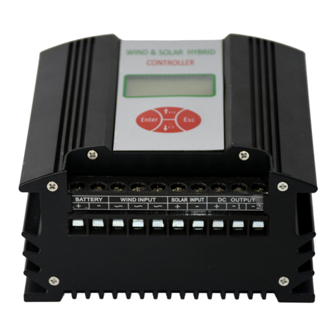
Winpower SWSB Series User manual

Let’s go green; Let’s win together
V1.0
i
SWSB Series
Economical wind&solar hybrid controller
User Manual
SP Model
200W 12V WWS02-12B
400W 24V WWS04-24B
600W 24V WWS06-24B

Let’s go green; Let’s win together
V1.0
ii
CONTENTS
1. Important Safety Warning............................................................................................................ 1
2. Basic I Information........................................................................................................................ 2
2.1 Introduction and Features........................................................................................................2
2.2 Product Structure.....................................................................................................................3
3. Product Installation........................................................................................................................4
3.1 Installation Notes.....................................................................................................................4
3.2 Installation and Wiring............................................................................................................ 5
3.2.1 Installation Steps.............................................................................................................. 5
3.2.2 Electrical Connection....................................................................................................... 6
4. Operation Interface Introduction................................................................................................. 7
4.1 LED Display............................................................................................................................7
4.2 LED Information Define......................................................................................................... 7
4.3 Load Output Modes.................................................................................................................8
4.4 Parameters Setting...................................................................................................................9
5. Trouble Shooting........................................................................................................................ 11
6. Technical Parameters................................................................................................................. 13
7. Warranty..................................................................................................................................... 16

Let’s go green; Let’s win together
V1.0
1
1. Important Safety Warning
Before Using the controller, please read all instructions and cautionary markings on the unit
and this manual. Store the manual where it can easily be accessed.
This manual includes all safety warnings, installation, and operation guidance of SWSB series
wind&solar hybrid controllers.
Before installing and using this controller, read all instructions and cautionary markings on the
controller and all appropriate sections of this guide.
Do not use the machine in the place where has flammability and explosive gas/articles. Beware
of flames and sparks.
Please Contact our after-sales person if the machine doesn’t work.
Do not change the electrical components and parts yourself, or we will not be responsible for the
warranty items and related duties.
Please install the machine indoor to avoid the rain water enter the controller inside.
Please keep good ventilation and heat dissipation.
Please install a circuit breaker outside the controller if conditions are allowed.
Please use copper cable for line connection, and choose the right diameter of cable according to
the actual current.
To avoid a risk of fire and electric shock, make sure the existing wiring is in good condition and
that the wire is connected tightly.
Do not restart the controller immediately when it alarms. Please analyze the fault reasons and
repair them at first.

Let’s go green; Let’s win together
V1.0
2
2. Basic I Information
2.1 Introduction and Features
SWSB series is a kind of economical wind&solar hybrid controller.
Features
Apply for independent wind &solar hybrid system, lighting system and monitoring system.
LED Display
Complete protection functions

Let’s go green; Let’s win together
V1.0
3
2.2 Product Structure
Chart1. Product Overview
①
Battery terminal
④
Load terminal
②
Wind turbine terminal
⑤
Button
③
PV panel terminal
⑥
LED Display

Let’s go green; Let’s win together
V1.0
4
3. Product Installation
3.1 Installation Notes
1) The machine should be kept indoors and well ventilated;
2) Environment temperature: -20~+40℃; Humidity: <=95%,no condensing
3) Altitude should not be more than 40000m。(when the altitude is more than 1000m, the machine
should be used according to the GB/T3859.2 regulations)
4) Avoid using the machine in direct sunlight, sun exposure, rain, humidity, acid fog, and dust.
5) To guarantee the lifespan, it is suggested that the space around the device has no other items
within 30CM.
6) The machine can only charge for the battery in the rated voltage range.
7) The machine can only be connected to the wind turbine and PV with allowed power and voltage.

Let’s go green; Let’s win together
V1.0
5
3.2 Installation and Wiring
3.2.1 Installation Steps
Please refer to the specific installation situation. Generally speaking, if it is used in street light pole,
you can fix the controller to the rail inside the light pole.
If it is installed in the power box, the power box is drilled according to the hole size, and the
controller is fixed with M4 screw.
Chart 2: Installation Steps

Let’s go green; Let’s win together
V1.0
6
3.2.2 Electrical Connection
Chart 3: System Overview
Please connect those parts according to the order of ①-④, and notice the following items.
1) Connect the load positive and negative terminal to the “DC OUTPUT” terminals
as“+”“-1”“-2”relatively. 2 output loads share the same “+” terminal.
2) Connect the battery bank to the controller by the terminal which marks “BATTERY”. (do not
reversed the connection of positive and negative terminals)
3) When wind turbine is still or running in a low speed, connects its output cable to the “WIND
INPUT” terminal on the controller.
4) Connected the terminals of solar panels to “SOLAR INPUT” terminals “+”“-”on the controller;

Let’s go green; Let’s win together
V1.0
7
5) Check all the connection to make sure they are connected rightly and tightly.
4. Operation Interface Introduction
4.1 LED Display
After the power is connected, the whole screen is in a browsing status. It shows battery voltage, and
can be changed to the following information by press related buttons.
4.2 LED Information Define
Name
Icon
Status
Wind Turbine
Unload or brake icon
Indicator light keeps on means brake automatically.
Indicator light flickers means manual brake.
PV
Night icon
Indicator light is on means PV voltage is lower than
light control on voltage.
Battery
Undervoltage icon
Indicator light is on means the battery is under
voltage.
Load
Load status
Indicator light flickers means short circuit.
Indicator light keeps on means overload.

Let’s go green; Let’s win together
V1.0
8
Buttons
Set icon
Indicator light is on means it is at the setting status.
Indicator light is off means it is at the browsing
stauts.
Light control icon
Indicator light is on means it is on the light control
voltage interface.
Load1 load output
Load2 load output
Show next parameter when it’s pressed at browsing
status.
Change to next value of the parameter or add the
value of the paremeter when it’s pressed at setting
status.
Enter to the setting status when it is pressed at
browsing status.
Save the parameters and back to browsing status
when it is pressed at setting status.
It can recover the output as it is pressed when the
load default is solved.
Press these two buttons at the same time, and it will
begin unloading.
Parameters display
Show current parameters
4.3 Load Output Modes
7 load output modes optional, and can be set on buttons.

Let’s go green; Let’s win together
V1.0
9
①
light control off / on
⑤
Keep on
②
Light control on,
time control off
⑥
Keep off
③
Light control on, time control
half power, light control off.
⑦
Keep half power
④
Light control on, time control
half power, time control off.
4.4 Parameters Setting
When you need adjust specific parameters, Please follow below steps:
1. Press “READ” to browse the interface, and the relative indicator light will be on, and then press
“SET/RESET” to enter setting status.
2. Press “READ” again to change the parameters.
3. Save the setting and back to the browsing status by pressing “SET/RESET”.
See the following table for specific parameter setting:
Settings
Operation Steps
Operation Interface
Load keep on output mode
1. Press “READ” to enter Load1 or Load2
interface, and “Load1”or “Load2” indicator
light will be on relatively.
2. Press “SET/RESET”, and “set” indicator
light will be on.
3. Press “READ”, and the value will add
one relatively every time, until the LED
display shows “n”.
4. Press “SET/RESET” to save the
parameters and back to browsing status.

Let’s go green; Let’s win together
V1.0
10
Load light control on/off
1. Press “READ” to enter Load1 or Load2
interface, and “Load1”or “Load2” indicator
light will be on relatively.
2. Press “SET/RESET”, and “set” indicator
light will be on.
3. Press “READ”, and the value will add
one relatively every time, until the LED
display shows “L”.
4. Press “SET/RESET” to save the
parameters and back to browsing status.
Load light control on, time
control off
1. Press “READ” to enter Load1 or Load2
interface, and “Load1”or “Load2” indicator
light will be on relatively.
2. Press “SET/RESET”, and “set” indicator
light will be on.
3. Press “READ”, and the value will add
one relatively every time.
4. Press “SET/RESET” to save the
parameters and back to browsing status.
Nixie tube shows one
value among “0-15”.
It means time control off
time.
Dark voltage point
1. Press “READ” to enter light interface,
and “Light” indicator light will be on
relatively.
2. Press “SET/RESET”, and “set”
indicator light will be on.
3. Press “READ”, and the value will add
one relatively every time.
4. Press “SET/RESET” to save the
parameters and back to browsing status.
Light control on
voltage=0.2*N*X
N=Rated power/12V
X=setting value(5 is
factory default,(0~
19)settable)
Daybreak voltage point
Change with dark voltage
Light contrl off
voltage=0.2*N*X+0.6*N

Let’s go green; Let’s win together
V1.0
11
Battery power
The value showed on LED display will
increase one (until add to “5”) once the
controller voltage increases 1V (0.5V
for 12V controller).
The value showed on LED display will
decrease one (until reduce to “0”) once
the controller voltage increases 1V
(0.5V for 12V controller).
“0”means the battery
voltage is lower than
11V(12V system) or
22V(24V system).
“2”means rated
battery voltage.
“5”means battery is
fully charged.
5. Trouble Shooting
Fault Type
Description
Possible reasons and solutions
No display on
LED
The connection between the battery and
the controller is not tight
Check the wiring, and reconnect it.
DC breaker is not on between battery
and controller
Turn on the breaker
Keypad failure
Contact after-sales person, and send
back to the factory for repairing.
The battery is connected negatively to
the controller.
Need change the internal fuse in
controller, and reconnect to the
battery.
No charging
The connection cable between wind
turbine and controller is loose.
Reconnect the cable tightly.
Wind turbine output voltage haven’t
reached the charging voltage
Check whether the system voltage is
reasonable.
The connection cable between PV and
controller is loose.
Reconnect the cable tightly.

Let’s go green; Let’s win together
V1.0
12
The PV is connected negatively to the
controller.
Reconnect the cable.
PV output voltage is not in accordance
with the system voltage.
Check the PV output and the system
parameters.
Indicator light keeps on, means overload.
Check if the load connection is
normal. Remove the over load , press
the “SET/RESET” button to recover
output.
Indicator light flickers, means short
circuit.
Check the connection and then press
“SET/RESET ”button to recover
output.
Indicator light is on, means
overdischarge.
Battery can’t be used until it is fully
charged. It need to be charged by
battery charger if the battery is
overdicharged for a long period.
Nixie tube
shows “5”
Battery is overcharged.
Check if the unload indicator light is
on, if yes, the system is normal. If
not, please check the battery
voltage and disconnect all the
parts and reconnect them.
Indicator light keeps on, wind turbine is
on unload status.
System can recover automatically
after waiting for 10mins.
Indicator light flickers,it is on manual
brake status.
Press “READ”“SET/RESET”at
the same time, to recover to
charge status.

Let’s go green; Let’s win together
V1.0
13
6. Technical Parameters
Model
WWS02-12B
WWS04-24B
WWS06-24B
Wind Turbine Input
Rated input
power
200W
400W
600W
Rated input
voltage
14Vdc
28Vdc
28Vdc
Input voltage
range
0~16Vdc
0~32Vdc
0~32Vdc
Rated input
current
17Adc
17Adc
25Adc
Manual brake
Press button “READ” “SET” at the same time to unload completely. Then recover
by hand.
Brake by over
current
17A (factory default,0~17A settable) Unload
completely when reached the set current, and recover
automatically after working 10mins.
25A(factory default,
0~25A settable)Unload
completely when reached
the set current, and recover
automatically after
working 10mins.
Brake by
overvoltage
Refer to “output overvoltage” control
PV Input Parameters
Rated input
power
100W
200W
200W
Max. open circuit
voltage
24V
48V
48V
Rated input
current
9A
Reversed
YES

Let’s go green; Let’s win together
V1.0
14
connection
protection
Charge Parameters
Rated battery
voltage
12V
24V
Temperature
compensation
function(optional
)
-3mV/℃/2V
Output Parameters
Rated output
voltage
12V
24V
Output
overvoltage point
14.5V (factory default,
11Vdc~16Vdc settable)
29V (factory default,22Vdc~32Vdc settable)
Output
overvoltage
recovery point
13.2V (factory default)
26.4V (factory default)
Max. Output
current
17A
17A
25A
DC Load Output Parameters
Output loops
2 loops
Output control
mode
Both 2 loops could be set in 7 modes, such as light control on&off, light control on
and time control off.
Output voltage
range
10.8V~16V
21.6V~32V
Rated output
current
10A/each loop
Overload
protection
120% rated DC output -1min,150% rated DC output -10s

Let’s go green; Let’s win together
V1.0
15
Short circuit
protection
200% rated DC output, instant protection
General Parameters
Rectifier mode
Uncontrolled rectifier
Display mode
LED
Display
information
Battery voltage, light control voltage, 1st loop output mode, 2nd loop output mode.
Brake guidance.
Lightning
protection
YES
Conversion
efficiency
≥95%
Static loss
<0.5W
Environment
temperature
-20℃~+40℃
Humidity
5%~95%, No condensing
Noise
≤65dB
Cooling mode
Natural cooling
Installation mode
Wall-mounted
Cover protection
class
IP53
Product
dimension(W*H*
D)
123x150x62mm
Product net
weight
0.8kg

Let’s go green; Let’s win together
V1.0
16
7. Warranty
The product shall be in warranty for one year from production. Please take contract as the final one if
it has special terms on warranty.
This manual suits for next models
3
Table of contents
Other Winpower Controllers manuals