WR-G65DDCe Multichannel Coherent Application Guide
9
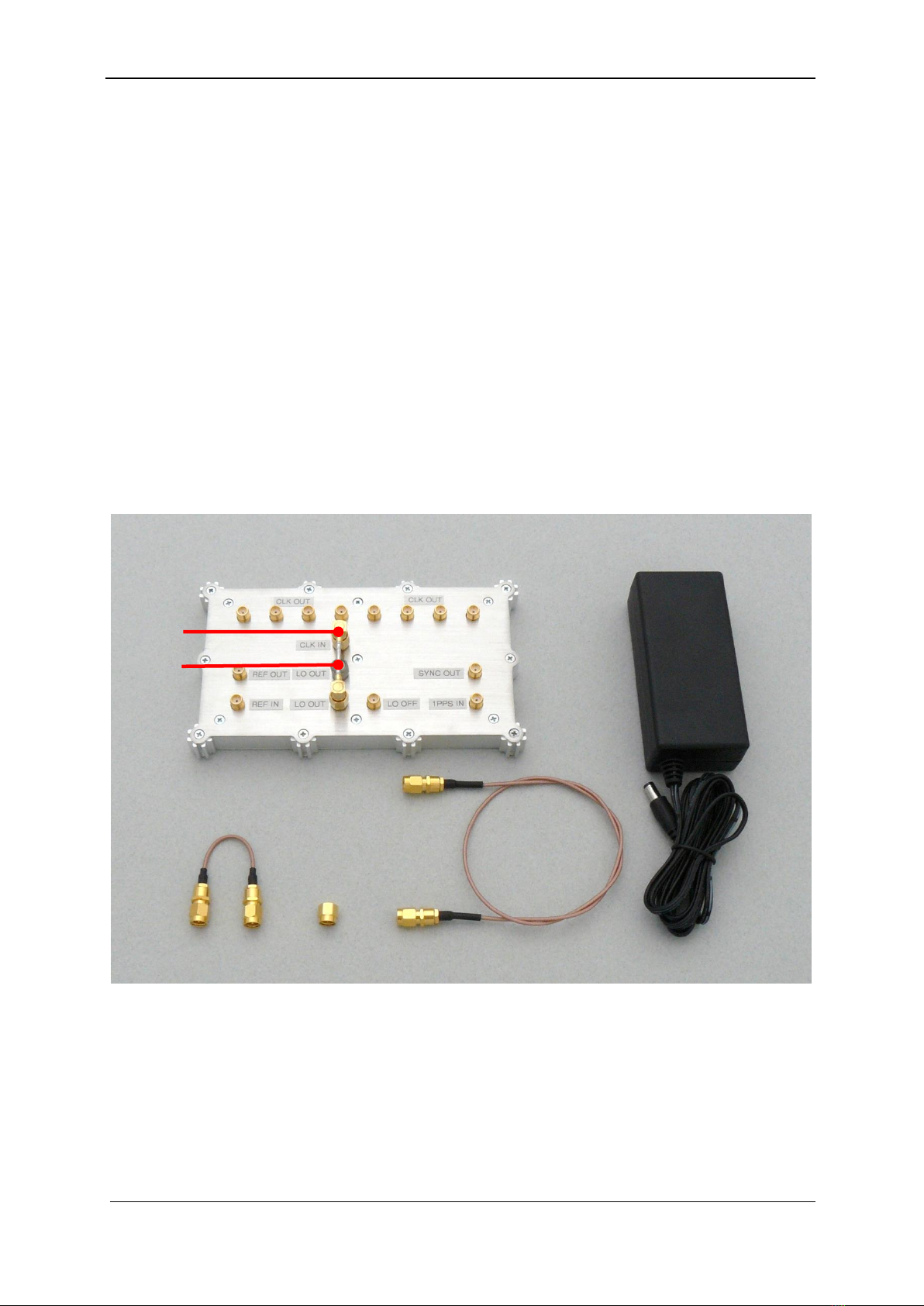
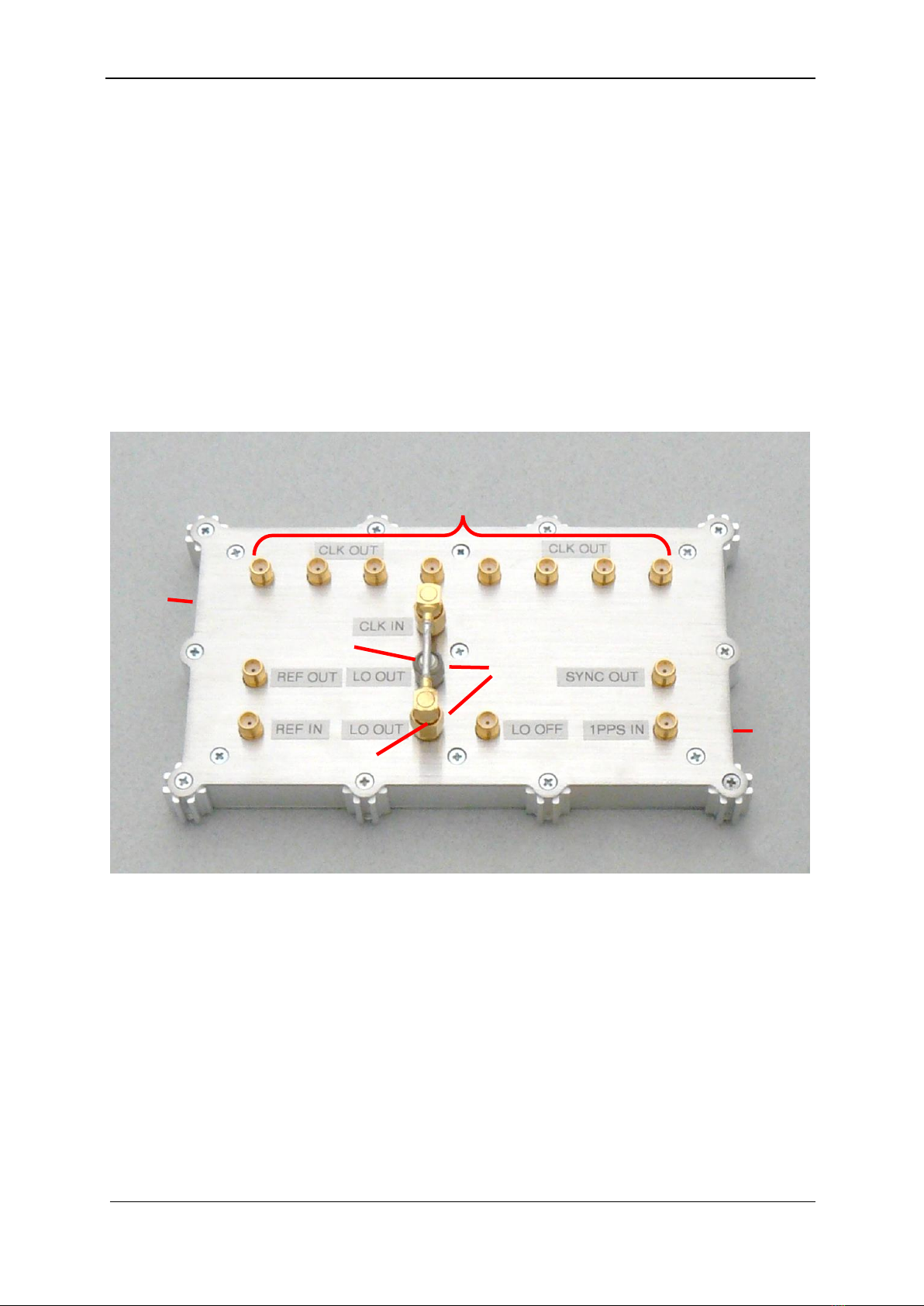
2.2.1.2 CLK OUT connectors for sampling clock output
There are eight SMA connectors for the sampling clock output provided on the Coherent
clock generator unit. These are located on the top of the unit and are facing upwards. The
CLK IN input of each WR-G65DDCe receiver within a coherent group must be connected to
one of these ports using the SMA patch cables (for coherent clock distribution) supplied with
the Kit and described in Section 2.2.2. All ports are equivalent; therefore, any receiver within
a coherent group can be connected to any of these ports. However, unused ports have to be
terminated using the 50 ohm SMA terminators for proper operation.
For the technical specification of the sampling clock output signal, please refer to Chapter 6.
2.2.1.3 Sampling clock oscillator input CLK IN
The CLK IN port drives all eight CLK OUT outputs. In other words, the sampling clock
provided at this port is coherently distributed to all eight CLK OUT outputs, therefore it must
always be connected to one of the two LO OUT output ports described in the next section.
This mandatory connection is factory installed as shown in Picture 2-10 and described in
Section 2.2.5.
The factory connection between the LO OUT port and the CLK IN port should not be altered
for normal operation when using the coherent clock generator unit to drive up to eight
coherent receivers.
The purpose of this connection is to enable the use of two coherent clock generator units
to coherently drive up to sixteen receivers. For details on how to use two coherent clock
generator units to drive up to sixteen receivers please refer to chapter 4 of this document.
2.2.1.4 Sampling clock oscillator outputs LO OUT
There are two LO OUT ports provided on the Unit. Both LO OUT ports provide the same
phase coherent 210 MHz sampling clock signal generated by the internal sampling clock
oscillator.
The purpose of the two LO OUT ports is to enable the use of two coherent clock generator
units to coherently drive up to sixteen receivers. For details on how to use two coherent
clock generator units to drive up to sixteen receivers please refer to chapter 4 of this
document.
For the standard operation of a single Coherent clock generator unit driving up to eight
receivers, one of these ports has to be connected to the CLK IN port on the unit. The other
one has to be terminated using a 50 ohm SMA terminator.
This mandatory connection between the LO OUT port and the CLK IN port is factory installed
as shown in Picture 2-10 and described in Section 2.2.5. It consists of a SMA jumper cable
connecting the LO OUT port and the CLK IN port. This interconnects the sampling clock from
the sampling clock oscillator output LO OUT to the CLK IN input of the Coherent clock
generator unit. The other unused LO OUT port is terminated using a 50 ohm terminator.