Winterhalter UC Series User manual

Assembly instructions | 89014662; 2022-04 | 1
1 Introduction
1.1 About these operating instructions
These instructions contain information for the installation and connection of a dosing unit of a competitor. Dosing units of a competitor
are dosing devices that do not come from Winterhalter Gastronom GmbH. To be able to work safely with the dosing device, the safety
and operating instructions provided must be observed. Compliance with the valid national accident prevention regulations and general
safety provisions must be ensured.
1.2 Copyright
The instructions are protected for the manufacturer by copyright.
The instructions contain guidelines and drawings or parts of drawings of a technical nature, which may not be reproduced, distributed,
used for the purposes of competitors without authorisation or shared with others, either in whole or in part.
The operator of the warewasher is permitted to make copies, in whole or part, expressly for internal application relating to the operation
of the dishwasher. The manufacturer is entitled to claim damages for any infringements. Further rights reserved.
© 2022 by Winterhalter Gastronom GmbH
1.3 Proper use
– The dosing device is used for the automatic dosing of detergent or liquid rinse aid in commercial warewashers.
– The dosing device is a technical device for commercial use only.
– Train operating personnel in handling the dosing device and point out safety notes.
1.4 Improper use
– Children must not be allowed to play with the dosing device.
– Do not install dosing devices inside or on cover elements of Winterhalter warewashers.
– Winterhalter Gastronom GmbH assumes no liability for any damage caused by improper use of the dosing device.
To avoid damaging the warewasher and to achieve a good wash result:
– Do not use acidic detergents.
– Do not use foaming products (e.g. manual washing-up liquid) for pre-treating the wash items.
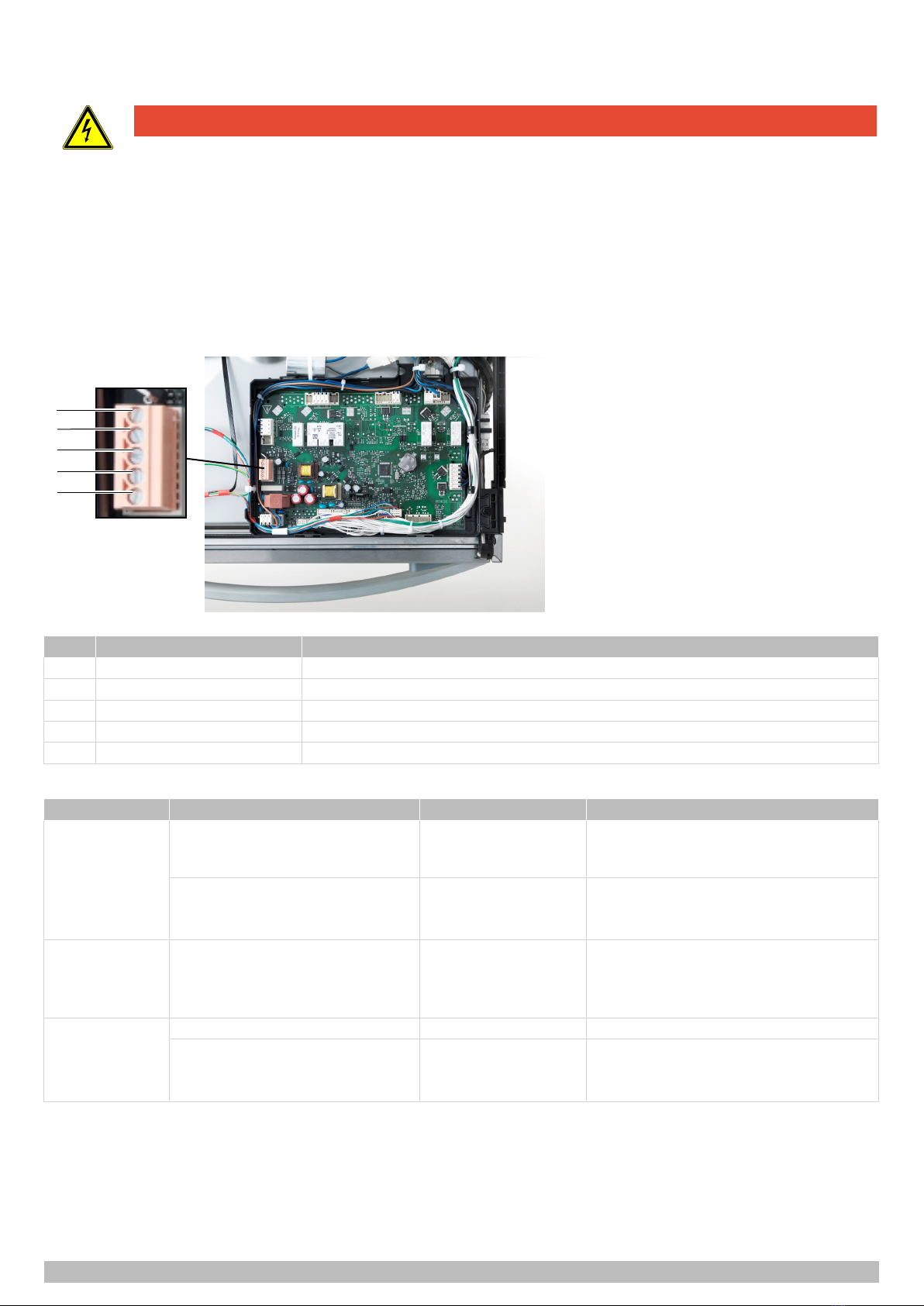
2 Safety notes
– The additional devices may be connected to the electrical mains supply only by a specialist company registered within the elec-
trical trade and approved by the energy supplier.
– Work on the electrical system, installation and maintenance work as well as repairs may be carried out only by qualified specialists.
– When working on the electrical system, doing installation and maintenance work as well as repairs, observe the electrical engineer-
ing safety rules to avoid electrical accidents:
– Disconnect all power supply points.
– Secure the machine against being switched on again.
– Check that there is no voltage present.
– Earth and short circuit.
– Cover or cordon off neighbouring parts that are live.
– Touching live components can lead to death by electric shock. In the event of a defect or damage to an electrical component /
cable or its insulation, switch off the power supply immediately and arrange for its repair by a specialist.
Connection of external dosing devices to UC Series V02
Assembly instructions

2 | 89014662; 2022-04 | Assembly instructions
3 Connecting the dosing tubes and suction tube
Terminals
1 3 42 5 6
Item Name Note
1 Entries for hoses and cables Rear view
2 Connection for detergent dosing hose Front view
3 Connection for rinse aid dosing hose UC-M, UC-L, UC-XL
4 Plug for detergent suction tube with empty indicator White plugs
5 Plug for rinse aid suction tube with empty indicator Blue plugs
6 Connection for rinse aid dosing hose UC-S, rear view
Connections for detergent and rinse aid dosing for hoses with an inner diameter of 5 mm are available on the warewasher.
ØDisconnect the warewasher from the electrical mains supply and secure against unintended activation.
ØRemove the front cover from the warewasher.
ØRemove partition wall to the electrical installation area.
ØIf present, remove Winterhalter dosing device and insulate electrical connections.
ØInstall the dosing device on-site.
ØLead the dosing hose and the connection cable through at the intended point on the back of the warewasher chassis (1).
ØFasten detergent dosing hose to detergent connection (2) with wire hose clip.
ØFasten the rinse aid dosing hose to the rinse aid connection (3 / 6) with a wire hose clip.
ØConnect the connection cable of the suction tube on the plug (4 / 5).
ØEnsure that the dosing hose and connection cable are guided kink-free.
ØInstall partition wall to the electrical installation area.

Assembly instructions | 89014662; 2022-04 | 3
4 Install conductance-controlled dosing device
NOTE
Danger of rusting and clogged jets caused by drilling swarf!
Rusting drilling swarf can also cause “stainless steel” to begin to rust.
ØRemove drilling swarf from the interior of the warewasher.
Note:Do not use a conductivity-controlled dosing device on warewashers with a built-in water softener. Regeneration salt that
enters into the tank can falsify measured values.
185
175
4.1 Install measuring electrode
ØOpen door.
ØRemove wash field, strainer, filter cylinder and filter bottom.
ØLine the interior of the tank with cloths or suitable paper to catch drilling swarf.
ØDetermine the size of the drill hole according to the measuring electrode.
ØDrill a hole for the measuring electrode at position (1).
ØDeburr the drillhole.
ØRemove drilling swarf from the interior of the warewasher.
ØInstall measuring electrode.
ØLead the connection cable of the measuring electrode to the dosing device.

4 | 89014662; 2022-04 | Assembly instructions
5 Establish the electrical connection of the dosing device
DANGER
Electric shock from live components
A fatal electric shock can occur during installation and maintenance work and when carrying out repairs.
ØIsolate and lockout the mains supply to the warewasher.
ØCheck that there is no voltage present.
Note:Maximum current drain at the transfer strip: 0.5 A. Connect only external dosing devices with their own fuse protection.
Include the dosing device in the protective circuit (PE) of the warewasher.
ØDisconnect the warewasher from the electrical mains supply and secure against unintended activation.
ØDetermine the connection and configuration according to the dosing device type (}7).
ØConnect external dosing device to transfer strip.
ØConfigure the transfer strip (}5).
1
2
3
4
5
Figure: Transfer strip
Item Name Note
1 DETERGENT For detergent dosing device (type-dependent)
2 WASH For detergent dosing device (type-dependent)
3 RINSE For rinse aid dosing device
4 N Neutral / phase 2
5 L1 Continuous voltage / phase 1
Depending on the configuration of the transfer strip, voltage is present at the RINSE and DETERGENT terminals.
Terminal Voltage present Condition Restriction
DETERGENT While machine fills – Door closed
– Minimum water level
in the tank
Parallel to solenoid valve
– While machine fills
– During the rinse
– Door closed – Not during the self-cleaning programme
WASH Parallel to wash pump – Door closed – Not during the self-cleaning programme
– Not while the machine is being filled
– Not during the descaling and basic clean-
ing programme
RINSE Parallel to rinse pump – Door closed – Not during the self-cleaning programme
Parallel to solenoid valve
– While machine fills
– During the rinse
– Door closed – Not during the self-cleaning programme
6 Start up the dosing device
ØClose the cover of the warewasher.
ØSwitch on the mains voltage and switch on the warewasher.
ØPut the dosing device into operation properly.
ØCarry out safety inspection in accordance with DIN VDE 701.
ØActivate several washing programmes and check the warewasher and installed components for leaks.

Assembly instructions | 89014662; 2022-04 | 5
7 Configuring the transfer strip
The transfer strip is configured in the chef menu.
Access the chef menu
1575
62°C
85°C
A PIN protects the menu from unauthorised access. The PIN is 1575. If you enter your PIN incorrectly three times in a row, input will be
blocked for 10 minutes.
Setting the detergent dosing device
32
1
Item Name Note
1 Reset to default setting
2 While machine fills For dosing devices with a fixed output (type-dependent)
Parallel to solenoid valve For dosing devices with adjustable output
3 Save settings
Setting the rinse aid dosing device
32
1
Item Name Note
1 Reset to default setting
2 Parallel to rinse pump For dosing devices with fixed or adjustable output (type-dependent)
Parallel to solenoid valve
3 Save settings

6 | 89014662; 2022-04 | Assembly instructions
8 Setting the dosing amount
Dosing amounts depend on the rinse water consumption and the tank capacity of the warewasher.
Rinse water consumption (l/rack)
The rinse water consumption depends on the on-site conditions and is adjusted during commissioning. Specified values correspond to
the factory setting under ideal conditions.
Machine type UC-S UC-M, UC-L, UC-XL
Glasswasher 2.0 2.2
Glasswasher optional Cool 3.4 3.4
Dishwasher 2.0 2.2
Bistro warewasher 2.0 2.2
Cutlery washer 3.2 3.4
Tank capacity (litres)
Filling UC-S UC-M, UC-L, UC-XL
Initial filling 7.1 11.5
During operation 9.5 15.3
Flow rate solenoid valve
Flow rate solenoid valve UC-S / UC-M / UC-L / UC-XL:
– Variant Standard: 4 l/min
– Variant Energy: 3 l/min

Assembly instructions | 89014662; 2022-04 | 7
9 Connection examples for different dosing device types
9.1 Connect and adjust detergent dosing device
Dosing device with fixed output and time relay
For dosing devices with fixed output and a time relay, only post-dosing can be controlled. The pre-dosing can also be controlled with
two time relays.
With one time relay:
ØConnect to WASH terminal (}4).
ØSet time relay on the dosing device.
ðWhen the wash pump is running, detergent is dosed during the set time.
With two time relays:
ØConnect a time relay to the DETERGENT terminal (}4).
ØSet detergent dosing device to “While machine fills” (}5).
ØSet the time relay on the dosing device for dosing during the initial filling of the warewasher.
ðWhen the warewasher is filled for the first time, detergent is dosed during the set time.
ØConnect a time relay to the WASH terminal.
ØSet time relay on the dosing device.
ðWhen the wash pump is running, detergent is dosed during the set time.
Dosing device with adjustable output
For dosing devices with an adjustable output, detergent can be dosed in parallel with the opening time of the solenoid valve. Detergent
is then dosed during the initial filling of the tank and with each rinse. The output must be adjusted to the flow rate of the solenoid valve.
Calculating the output:
– Flow rate solenoid valve [l/min] x desired concentration [ml/l] = output [ml/min]
– Example: 4 l/min x 3.0 ml/l = 12.0 ml/min
ØConnect to DETERGENT terminal (}4).
ØSet output on the dosing device.
ØSet detergent dosing device to “Parallel to solenoid valve” (}5).
ðDuring the initial filling and when the rinse pump is running, detergent is dosed at the set output.
9.2 Connect and adjust the rinse aid dosing device
Dosing device with fixed output and time relay
ØConnect to RINSE terminal.
ØSet time relay on the dosing device.
ØSet the rinse aid dosing device to “Parallel to rinse pump” (}5).
ðWhen the rinse pump is running, rinse aid is dosed during the set time.
Dosing device with adjustable output
Calculating the output:
– Flow rate solenoid valve [l/min] x desired concentration [ml/l] = output [ml/min]
– Example: 4 l/min x 0.3 ml/l = 1.2 ml/min
ØConnect to RINSE terminal (}4).
ØSet output on the dosing device.
ØSet the rinse aid dosing device to “Parallel to rinse pump” (}5).
ðWhen the rinse pump is running, rinse aid is dosed with the set output.
Other manuals for UC Series
1
Other Winterhalter Industrial Equipment manuals
Popular Industrial Equipment manuals by other brands

Raytools
Raytools BM114S Series user manual

Ortlinghaus
Ortlinghaus TPI 1570 EN Translation of original operating manual

WPT POWER
WPT POWER PTO Installation and maintenance manual

ABB
ABB HT593960 original operation manual

Montanari
Montanari NOR Installation, use and maintenance instructions

Centrometal
Centrometal CM WiFi-box Technical instructions