Winterhalter DuoMatik 3 User manual

DuoMatik 3
Operating instructions / Connection diagram / Commissioning instructions .................................. 7 - 12
GB


7
Operating instructions
for the Winterhalter DuoMatik 3 softener
1 Safety notes
For safe use of the softener, please read the
safety notes listed here carefully.
1.1 Explanation of symbols used
The following symbols are used in these instructions:
Caution
Warns of potential defects or destruction of the
product when the provided safety measures are
not observed.
IMPORTANT An important tip is given here.
INFO A useful tip is given here.
These arrows indicate procedural instructions.
This symbol indicates the results of your actions.
This symbol indicates lists
1.2 Intended use
The DuoMatik 3 softener is a device for water softening of fresh
water for use in commercial warewashers and may only be used
for this purpose. The softener is installed between the fresh water
pipe and the warewasher. The fresh water must be of drinking wa-
ter quality from a microbiological point of view.
The softener is a technical piece of equipment for commercial use
and is not intended for private use.
Any alterations to the design or to use of the device performed
without the written approval of Winterhalter Gastronom GmbH will
lead to the guarantee and product liability becoming void.
Winterhalter Gastronom GmbH will not accept liability for any
damage caused by failure to use the device in accordance with
the intended use.
1.3 Safety notes for maintenance and repairs
Maintenance and repairs may only be performed by authorised
Winterhalter service technicians. Unprofessional maintenance or
repairs may lead to considerable dangers for the user for which
Winterhalter cannot be held liable.
Only original spare parts by Winterhalter may be used for mainte-
nance or repairs. Use of spare parts that are not original spare
parts invalidates the warranty.
1.4 General safety notes
Read the safety and operational notes included in these operating
instructions carefully. Keep these operating instructions in a safe
place for later reference. Failure to observe the safety notes and
operating instructions voids all liability and warranty claims against
Winterhalter Gastronom GmbH.
Only work with the softener after reading and understanding the
operating instructions. Winterhalter Customer Service will be glad
to provide you with information on how to operate the device and
how it functions. The softener may only be operated as described
in these operating instructions.
2 Product description
The softener consists of a mobile plastic container and a removable
cover. The regeneration salt is placed into the container.
Two cartridges are integrated into the container. The cartridges are
filled with exchange resin and are connected together.
Water softening is based on the principle of ion exchange. The
exchange resin in the cartridges binds with the hardening ions from
the raw water flowing through the device and releases other non-
hardening ions into the water. The softened water has a total hard-
ness of 0 °dH.
The capacity of the exchange resin is limited. It depends on the total
hardness of the raw water. The exchange resin must be regenerated
when it has been used up. The control head on the cartridges con-
trols regeneration depending on the water hardness set. When a
cartridge is depleted the unit switches to the second cartridge, and
the depleted cartridge is regenerated, ensuring that softened water is
continuously available.
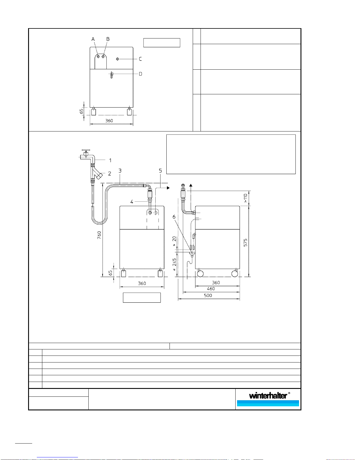
3 Installation and connection
3.1 Installation site requirements
The room must be frost-free.
A water drain must be located near the softener. The water drain
must not be higher than the safety overflow on the rear of the sof-
tener.
Ideally the room has a floor drain.
The installation location must be horizontal and even. Slight incli-
nations such as are usual in kitchens do not impair functioning,
however the softener should be secured against rolling.
The softener should preferably be installed on the floor. If the
softener is placed on a base, the castors should be removed.
There should be sufficient space above to ensure that the cover
can be removed easily during the refilling of regeneration salt.
See connection diagram for connections for water inlet and water
drain (page 10).
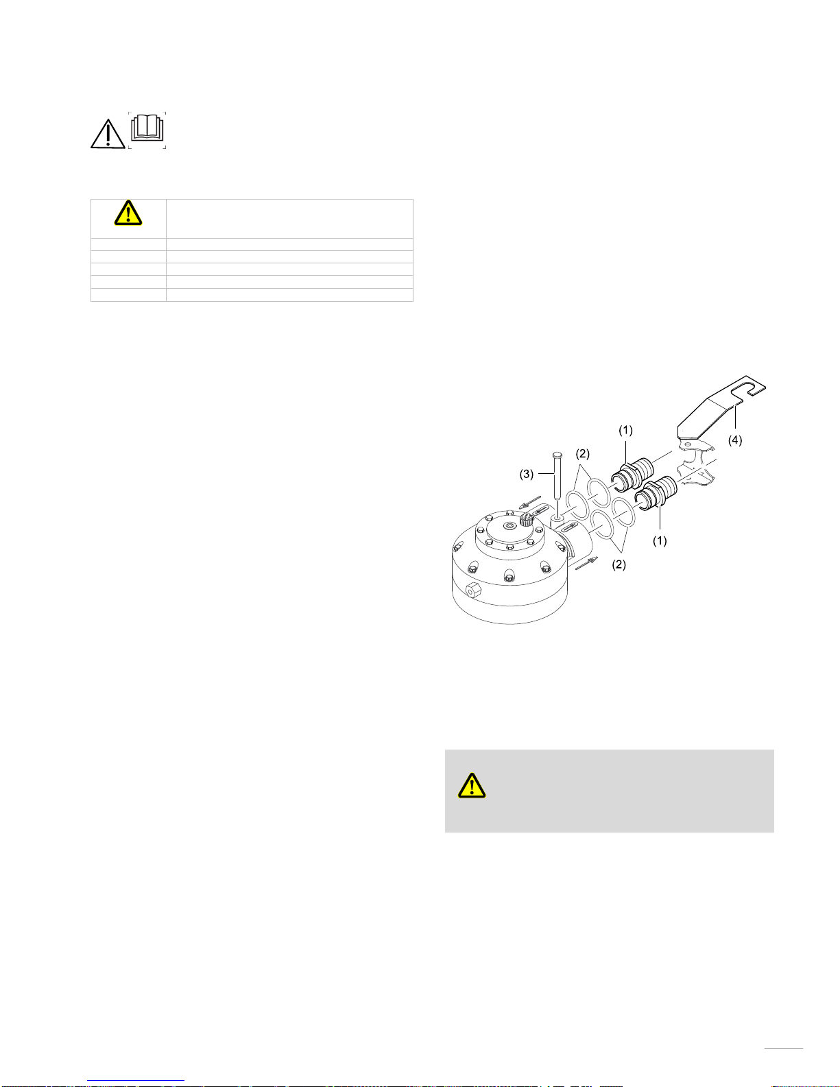
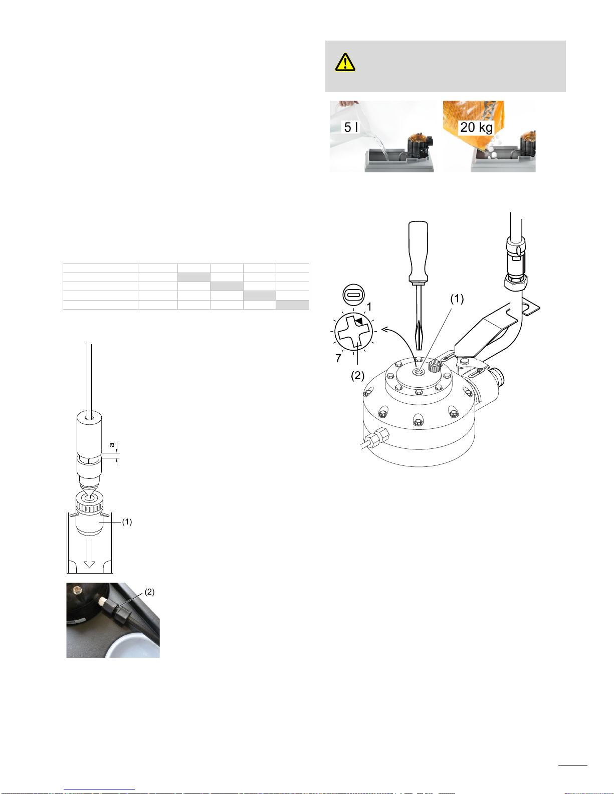
3.2 Preparing control head
Remove the cover of the container.
Take the hoses and assembly kit out of the container.
Equip the adapters (1) with the O-rings (2) and grease with sili-
cone grease.
Plug the adapters (1) onto the "in" and "out" connections.
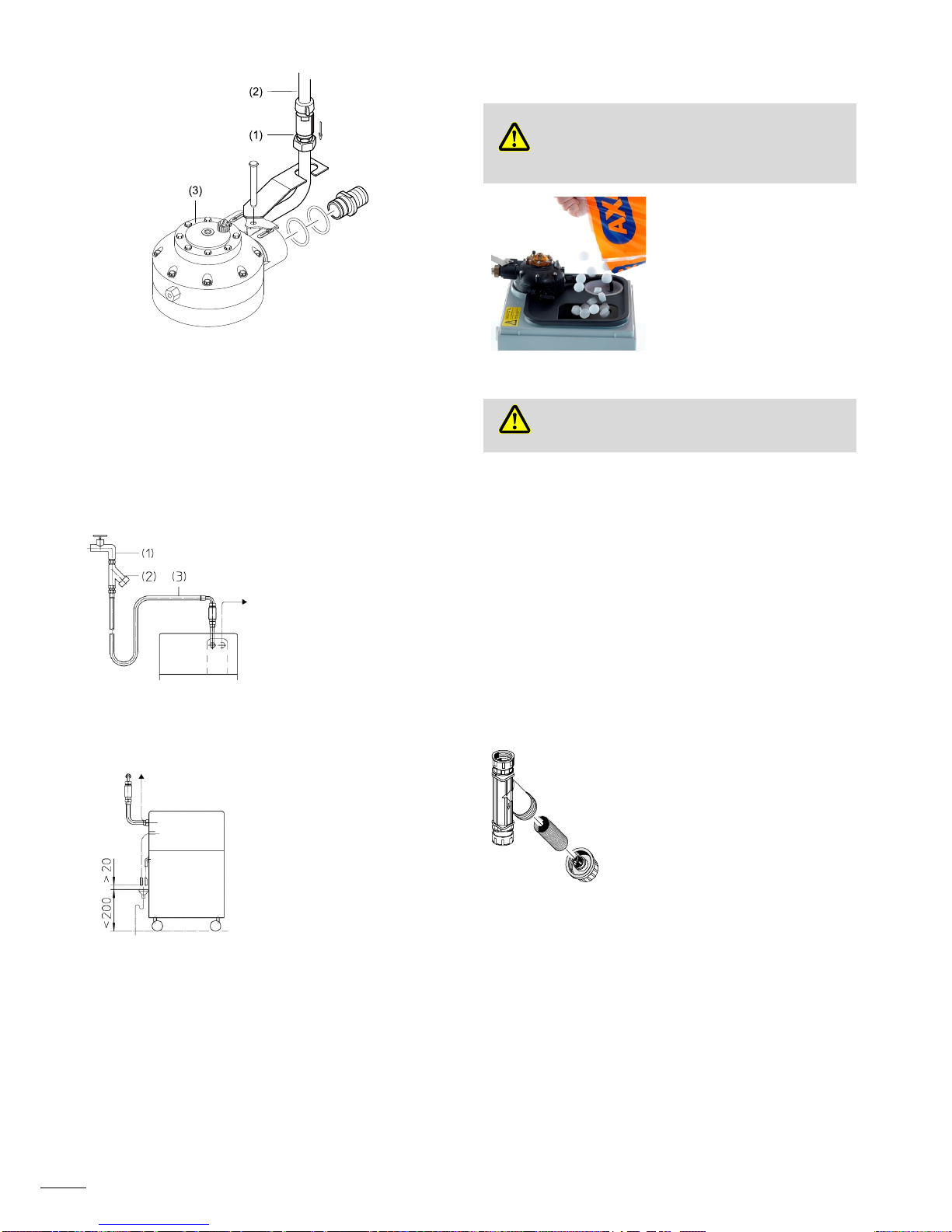
Secure with handle (4) and pin (3).
3.3 Connecting
Caution
Connection of the softener to the drinking water network
and to the waste water must be performed according to
the country-specific, local conditions by an approved
water fitter.
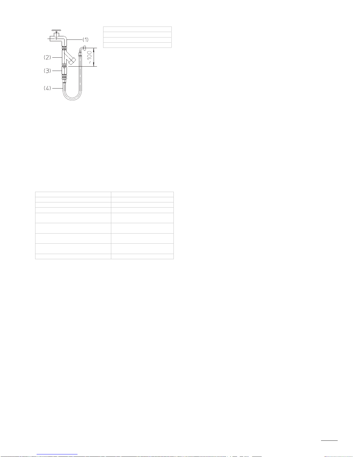
National installation and operating regulations as well as
details on the connection diagram on page 10 must be
observed.
03 / 2017-02

8
3.4 Connecting the water safety device
A water safety device (1) must be used in order for the softener to be
operated in accordance with DIN requirements. A kit is available
from Winterhalter for this purpose.
The kit contains a backflow preventer type HD in accordance with
DIN EN 1717.
Installation of the water safety device is shown in the drawing.
Should national guidelines not require a check valve or anti-vacuum
device, the water supply hose (2) is connected directly at the control
head (3).
3.5 Installing dirt trap
After the water stop cock (1),
install a dirt trap (2) with a
mesh width of 150 µm.
INFO The dirt trap en-
closed with Win-
terhalter warewash-
ers is suitable for this
purpose.
Connect supply hose (3).
3.6 Connecting the waste water hose and overflow
hose
Attach waste water hose to the
hose nipple and secure with a
hose clamp.
Guide the waste water hose to
the on-site water drain.
Attach a hose to the safety
overflow on the rear of the sof-
tener and guide this to the on-
site water drain.
Attach both hoses to the water
drain at a distance of 20 mm
(see drawing).
4 Commissioning
After the machine has been correctly connected to the water supply
and waste water drain, contact your Winterhalter branch or your
dealer in order to request them to perform commissioning. You can
use this opportunity for you and your operating personnel to learn
how to operate the softener.
5 Operation
The softener works automatically following commissioning. Only the
regeneration salt must be refilled from time to time.
Caution
Possibility of damage due to incorrect salt.
Only use undenaturated evaporated salt (approx. 15 mm
granularity or in tablet form) marked as regeneration salt
for softeners. Do not use any other types of salt e.g.
table salt, rock salt or de-icing salt. These may contain
components that are not soluble in water.
Refill the regeneration salt as
soon as the water in the contain-
er is above the level of the salt.
6 Maintenance
Caution
Possibility of damage due to chemicals.
Do not clean the inside of the container with cleaning
agents or other chemicals.
Only ever clean the container with water.
Clean the outside of the softener using conventional plastic kitch-
en hygiene products.
7 Maintenance by service technicians
Have the softener examined at least once per year by an authorised
Winterhalter service technician.
7.1 Cleaning the inside of the container
Turn off the water supply.
Drain the container completely (scoop out salt and water).
Remove filters.
Remove any sludge or dirt particles using a cloth or brush.
Insert filters.
Open the water supply.
Refill new regeneration salt (approx. 20 kg).
7.2 Cleaning the dirt trap
Turn off the water supply.
Remove the dirt filter, clean it and reinsert
it.
Open the water supply.
7.3 Check backflow preventer type HD
Is the backflow preventer installed according to the connection
diagram (page 10)?
Is the backflow preventer clean?
No visible leakage, corrosion or other damage?

9
7.4 Check backflow preventer type HD
(1) water stop cock
(2) dirt trap
(3) backflow preventer
(4) hose
Close the water stop cock (1).
Install the backflow preventer (3) according to the drawing.
Keep the hose (4) above the level of the backflow preventer (3).
Slightly open the water stop cock (1) and close it again as soon as
water flows out of the hose (4).
Point the hose (4) down into a bucket.
Check the following points:
Does water flow out of the hose (4)?
Does the backflow preventer (3) audibly suck in air while water
is flowing out of the hose (4)?
Replace the backflow preventer (3) if it does not pass the test.
Reinstall the backflow preventer (3) according to the connection
diagram (page 10) and test according to section 7.3.
8 Technical data
Water inlet temperature max. 60 °C
Minimum flow pressure 250 kPa (2.5 bar)
Maximum inlet pressure 600 kPa (6 bar)
Pressure loss 100 kPa (1 bar)
Max. total hardness of raw water 45 °dH
(56 °e / 82 °TH / 8.1 mmol/l)
Flow rate
(at 2.5 bar inlet pressure)
max. 30 l/min
Salt consumption per regeneration
(for the brine valve standard setting)
approx. 0.3 kg
Water consumption per regenera-
tion
19 l
Weight (empty) 21 kg

10
Connection diagram
Position of the connections
A Water out
(softened water);
G ¾" external thread
B
Water supply (raw water)
G ¾" external thread;
min. 2.5 bar; max. 6 bar;
max. 60 °C;
max. 45°dH total hardness
C Regeneration water
½ " hose; 2000 mm long
D Safety overflow
½ " connection
Connection diagram
INFO Pos. 1 to 4 and pos. 6 are not included in the scope of supply
A water safety device (pos. 4) must be used in order for the softener to be operated in accordance with DIN requirements. A kit is
available from Winterhalter for this purpose.
The kit contains a backflow preventer type HD in accordance with DIN EN 1717.
National installation and operating regulations must also be complied with.
The system can also be mounted in mirror image. Provide on-site connections next to the device.
6 Waste water funnel with trap
5 Hose to warewasher
4 Water safety device
3 Supply hose; 2 x G 3/4" union nut
2 Dirt trap; 1 x G 3/4" union nut; 1 x G 3/4" external thread
1 Water stop cock on-site, G 3/4" external thread
89013537-00 Connection diagram
DuoMatik 3 softener
Prepared: 07.02.2017 sch
View from rea
r
View from front
If space is limited, the water safety device (pos. 4) can also be
installed in the water pipe somewhere else.
Note:
- Top edge of the combination connector must be at least
110 mm above the top edge of the device
- Vertical installation position
- Install in direction of flow

11
Commissioning instructions
for the Winterhalter DuoMatik 3 softener
These regulations are intended for correct commissioning of the
softener by an authorised Winterhalter service technician.
1 Testing installation
Test the following points:
Is it installed according to the operating instructions and the
connection diagram?
Is the water inlet temperature in accordance with the connec-
tion diagram?
Are the water pressures in accordance with the connection
diagram?
2 Converting total hardness
Water hardness is specified in the German degree of hardness (°dH)
in these instructions. Other units of measurement are used in other
countries.
Measure the total hardness and convert into the German degree
of hardness (°dH) using the following table:
°dH °e °TH mmol/l
German hardness 1°dH= 1.0 1.253 1.78 0.179
English hardness 1°e= 0.798 1.0 1.43 0.142
French hardness 1°TH= 0.560 0.702 1.0 0.1
mmol/l 1mmol/l= 5.6 7.02 10.00 1.0
3 Adjusting and installing the brine valve
Determine the total hardness of the
raw water:
Total hardness ≤40 °dH:
Use standard setting (5 mm).
Total hardness > 40 °dH:
Change distance (a) to 17 mm.
INFO The salt consumption per
regeneration increases
from 0.3 kg to 0.5 kg.
Ensure that the valve base (1) is
sitting in the recess of the container
base and that it is possible to move
the float cup vertically approx. 6 mm.
Fasten riser pipe of the brine valve
onto the control head using the en-
closed screw connections (2).
4 Adding regeneration salt
Caution
Possibility of damage due to incorrect salt.
Only use undenaturated evaporated salt (approx. 15 mm
granularity or in tablet form) marked as regeneration salt
for softeners. Do not use any other types of salt e.g.
table salt, rock salt or de-icing salt. These may contain
components that are not soluble in water.
5 Venting / manually triggering regeneration
Switch off the warewasher connected to the softener.
Slowly open the water inlet to the softener.
Turn the screw (1) slowly in a clockwise direction until the
regeneration begins (approx. 1 o'clock / 7 o'clock position).
Air and water must be emitted from the hose with regenera-
tion waste water.
After approx. 10 minutes no more water may be emitted
from the hose.
Turn screw (1) further clockwise into the 7 o'clock (or 1 o'clock)
position and vent the second cartridge in the same way.

12
6 Adjusting total hardness
IMPORTANT Before adjusting the total hardness, the manually
triggered venting must have been done (chap-
ter 5).
During the setting the device must not be in regen-
eration mode.
Determine the total hardness of the raw water.
See the table for the relevant setting value.
INFO The setting values in the dark columns are directly applied
to the setting disc (2).
Press down the setting button (1).
Turn the setting button (1) until the arrow (3) points centrally to the
required setting value in the viewing window.
IMPORTANT The arrow must not point to the black area.
INFO Each tooth deviation means 20 litres of softened water
more or less up until the next regeneration.
Switch on the warewasher connected to the softener.
Fill up the warewasher.
Check that the hose connections do not leak.
7 Instructing personnel
Instruct personnel in the following points:
Salt refilling
Maintenance and care
Total hardness [°dH] 4 5 6 7 8 9 10
Setting value 1 3 6 8 10 11 13
a [mm] 5 5 5 5 5 5 5
Softened water
between
2 regenerations
[l] 1512 1369 1165 1022 879 797 654
Total hardness [°dH] 11-
12
13-
14 15 16-
19
20-
23
24-
31
32-
40
41-
45
Setting value 14 15 16 17 18 19 20 20
a [mm] 5 5 5 5 5 5 5 17
Softened water
between
2 regenerations
[l] 593 511 450 368 307 225 164 164


Winterhalter Gastronom GmbH
Gewerbliche Spülsysteme
Winterhalterstraße 2─12
88074 Meckenbeuren
Deutschland
Telefon +49 (0) 75 42/4 02-0
Telefax +49 (0) 75 42/4 02-1 87
www.winterhalter.de
Winterhalter Gastronom GmbH
Commercial Dishwashing Systems
Winterhalterstrasse 2─12
88074 Meckenbeuren
Germany
Telephone +49 (0) 75 42/4 02-0
Telefax +49 (0) 75 42/4 02-1 87
www.winterhalter.biz
Right to make technical modifications is reserved
89013557-03/2017-02
Table of contents
Other Winterhalter Water Dispenser manuals
Popular Water Dispenser manuals by other brands

Puretec
Puretec SOL-2CI Series user guide

Miracle Water
Miracle Water MW-40 owner's manual

HydroCare
HydroCare O2 Hydro Well System Installation, use & care guide

Scarlett
Scarlett SC-1222 instruction manual

Everpure
Everpure DEV9108-11 Specifications

Canature WaterGroup
Canature WaterGroup 85UF/DF owner's manual