Wipaire WIPLINE 7000 User manual

SERVICE MANUAL & ICA
WIPLINE 7000 FLOATS
P/N 1004646 Revision P Page 1
SERVICE MANUAL & ICA
FOR THE
WIPLINE 7000 AMPHIBIAN FLOAT
ON THE
QUEST MODEL 100 KODIAK
Revision P
WIPLINE FLOATS • SKIS • MODIFICATIONS • AIRCRAFT SALES
AVIONICS • INTERIOR • MAINTENANCE • PAINT REFINISHING

SERVICE MANUAL & ICA
WIPLINE 7000 FLOATS
Page 2 Revision P P/N 1004646
THIS PAGE INTENTIONALLY LEFT BLANK

SERVICE MANUAL & ICA
WIPLINE 7000 FLOATS
P/N 1004646 Revision P Page 3
LOG OF REVISIONS
Rev Pages Description Date
A All Initial Release 6/11/2010
B All ECO 22037, See Doc W7001-34-01 8/17/2010
C All ECO 22043, See Doc W7001-34-04 9/9/2010
D All ECO 22090, See Doc W7001-34-03 10/8/2010
E All
Update to cover page logo, added instructions and G1000 Land/oatplane software
conguration to oat removal and Re-install checklists, added 3 blade propeller maintenance
section.
11/5/2012
F All Added Green Grease as an approved grease. 4/18/2013
G All
Updated Fig 1-6 for new oleo, updated Fig 4-4A, Fig 4-6 and added 4-4B, changes to MLG
rigging procedures, remaining paged repaginated, minor changes to oat install and removal
instructions.
5/30/2014
H All Added shear torque chart, PR 1440 C Sealant and Tef-Gel, removed warranty claim form.
Corrected 1200 was 1000, 1400 was 1150 and 1900 was 1300. 5/26/2015
J All Added Dow Corning DC4 and Mobil Aviation Grease SHC 100 to approved product list, update
exhaust system. 7/29/2015
K All
Removed “If the oats are installed, remove…” detail in inspection checklist, removed duplicate
inspection page, directed chapter 8 to document number 1009486, deleted list of gures and
tables.
2/1/2018
L 10 Added reference for Structural Repair Manual part number 1008274 in introduction. 5/1/2019
M 80 Added note for Main Landing Gear Axle Shaft in Maintenance Inspection Checklist. 9/5/2019
N35, 74-75,
77-81
Added note about STA-Lube. Added STA-Lube to Brake Caliper Grease. Removed Figure
9-1. Added information about corrosion limits. Removed inspection column from Maintenance
Checklist.
8/3/2020
P All Reformatted manual in new software. Removed Comet Industries GP-730A. Added sections
1.4 through 1.8. Added notes to Figure 9-1 and at the end of Section 9.3. 9/16/2022
View most current revision of this ICA at www.wipaire.com.

SERVICE MANUAL & ICA
WIPLINE 7000 FLOATS
Page 4 Revision P P/N 1004646
THIS PAGE INTENTIONALLY LEFT BLANK

SERVICE MANUAL & ICA
WIPLINE 7000 FLOATS
P/N 1004646 Revision P Page 5
CONTENTS
CHAPTER 1 INTRODUCTION AND GENERAL INFORMATION ........................................................................7
CHAPTER 2 AIRWORTHINESS LIMITATIONS ..................................................................................................25
CHAPTER 3 NOSE GEAR ....................................................................................................................................27
CHAPTER 4 MAIN LANDING GEAR BRAKES & GEAR RETRACTION ..........................................................35
CHAPTER 5 HYDRAULICS..................................................................................................................................53
CHAPTER 6 WATER RUDDER ............................................................................................................................59
CHAPTER 7 ELECTRICAL...................................................................................................................................63
CHAPTER 8 HARTZELL 3 BLADE PROPELLER ...............................................................................................65
CHAPTER 9 RECOMMENDED PROCESSES, PRODUCTS, & INSPECTION CHECKLISTS.......................67
CHAPTER 10 TROUBLESHOOTING ..................................................................................................................91
CHAPTER 11 INSTALLATION PRINT INFORMATION ......................................................................................97
APPENDIX .............................................................................................................................................................99

SERVICE MANUAL & ICA
WIPLINE 7000 FLOATS
Page 6 Revision P P/N 1004646
LIST OF FIGURES
FIGURE 1-1 FRONT VIEW ........................................................................................................................9
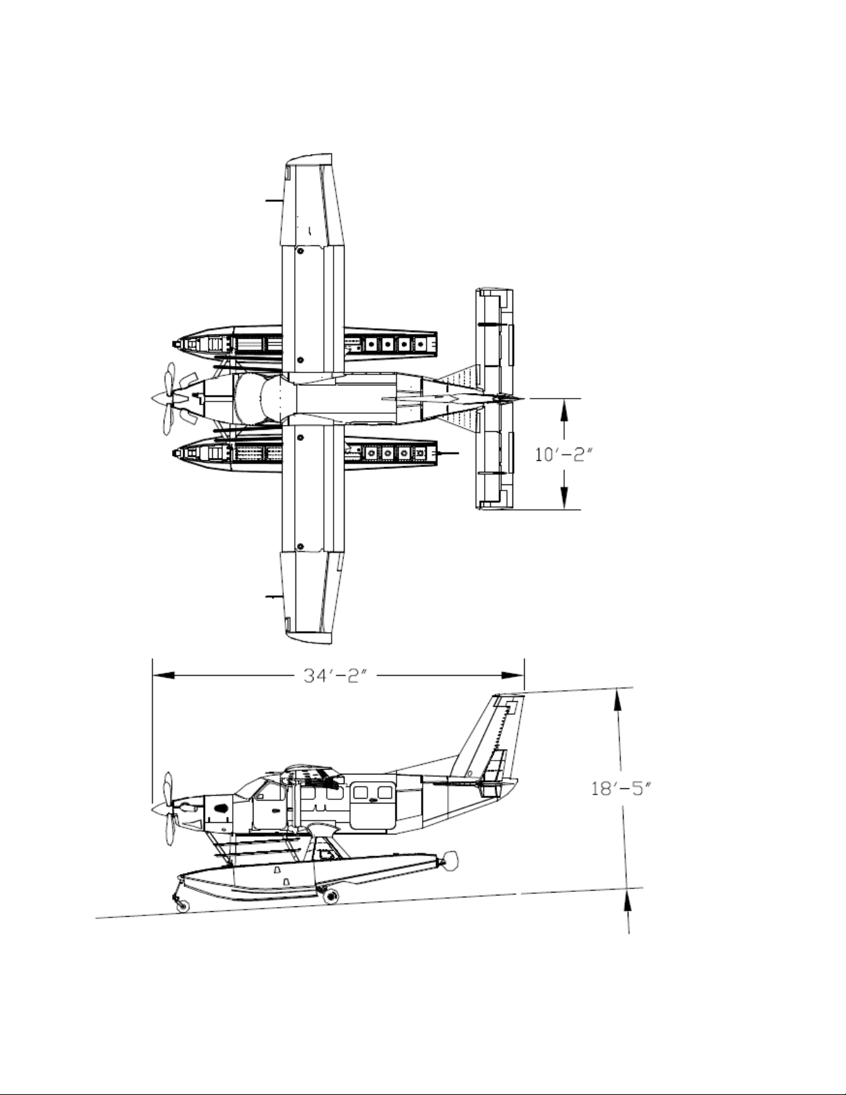
FIGURE 1-2 TOP & SIDE VIEWS............................................................................................................10
FIGURE 1-3 FLOAT TERMINOLOGY .....................................................................................................11
FIGURE 1-4 MAINTENANCE ACCESS POINTS...................................................................................12
FIGURE 1-5 HYDRAULIC FLUID LEVEL PLACARD ............................................................................14
FIGURE 1-6 FLUID TYPES AND QUANTITIES .....................................................................................14
FIGURE 1-7: JACK CRADLE RECOMMENDED MODIFICATION .......................................................20
FIGURE 1-8: JACKING LOCATION ........................................................................................................20
FIGURE 1-9: FLOAT SECURING LOCATIONS .....................................................................................21
FIGURE 1-10: FLOAT SECURING LOCATIONS OVERVIEW ..............................................................22
FIGURE 3-1 NOSE WHEEL & BOX.........................................................................................................29
FIGURE 3-2 NOSE WHEEL GREASING................................................................................................31
FIGURE 3-3 NOSE GEAR ITEMS...........................................................................................................33
FIGURE 4-1 MINIMUM BRAKE LINING THICKNESS...........................................................................37
FIGURE 4-2 MAIN GEAR, LOWER.........................................................................................................39
FIGURE 4-3 MAIN GEAR GREASING....................................................................................................41
FIGURE 4-4A MAIN GEAR ADJ. DOWN.................................................................................................42
FIGURE 4-4B MAIN GEAR ADJ. DOWN ................................................................................................43
FIGURE 4-5 MAIN GEAR ADJ. UP..........................................................................................................44
FIGURE 4-6 MAIN GEAR DOWN STOP ADJ.........................................................................................45
FIGURE 4-7 ROTARY ACTUATOR .........................................................................................................49
FIGURE 4-8 MAIN SHOCK STRUT.........................................................................................................50
FIGURE 5-1 HYDRAULIC SCHEMATIC .................................................................................................55
FIGURE 5-2 HYDRAULIC PLUMBING ...................................................................................................56
FIGURE 6-1 WATER RUDDER RETRACTION & EMERGENCY GEAR PUMP HANDLES...............60
FIGURE 6-2 WATER RUDDER CABLE ROUTING................................................................................61
FIGURE 9-1 FLOAT KIT INSTALLATION ITEMS...................................................................................77
FIGURE A-1 YAGI ANTENNAS INSTALLED ........................................................................................101
FIGURE A-2: CUFF REMOVAL..............................................................................................................101

SERVICE MANUAL & ICA
WIPLINE 7000 FLOATS
P/N 1004646 Revision P Page 7
CHAPTER 1 INTRODUCTION AND GENERAL INFORMATION
CONTENTS
1.0 INTRODUCTION.........................................................................................................................................8
1.1 GENERAL FLOAT INFORMATION..........................................................................................................13
1.2 CLEANING.................................................................................................................................................17
1.3 CORROSION.............................................................................................................................................18
1.4 TOWING.....................................................................................................................................................19
1.5 HOISTING..................................................................................................................................................19
1.6 LEVELING .................................................................................................................................................20
1.7 JACKING PROCEDURES........................................................................................................................20
1.8 JACK REMOVAL .......................................................................................................................................22
1.9 MOORING..................................................................................................................................................22

SERVICE MANUAL & ICA
WIPLINE 7000 FLOATS
Page 8 Revision P P/N 1004646
1.0 INTRODUCTION
This manual is provided for the owners of Wipaire model 7000 Floats as installed on the Quest model 100 Kodiak.
It has two main priorities: to inform owners of the level and amount of servicing required to properly maintain their
oatplane, and to provide technical data and servicing as specied to maintenance professionals charged with
servicing the oats.
When performing standard repairs for Wipline Aluminum Floats, please refer to the “Structural Repair Manual For
Wipline Aluminum Floats” part number 1008274. It is available free of charge online at www.wipaire.com.
The service products referred to throughout this manual are described by their trade names and may be
purchased from the Wipaire Parts Department.
We, at Wipaire, welcome your purchase and look forward to years of satisfying exchanges with you. Your oats
are built with pride and attention to detail, but we want that care to extend beyond your purchase. Our customer
service department is available for your questions 24 hours a day, 7 days a week, where ever you are in the
world.
Parts Sales and Technical Support Dept:
Wipaire, Inc.
1700 Henry Avenue – Fleming Field
South St. Paul, MN 55075
Telephone: (651) 306-0459
Fax: (651) 306-0666
Website: www.wipaire.com
Email: [email protected]
In this service manual we have worked hard to include many repair scenarios in addition to the recommended
products, practices, and routine maintenance required to keep your oats in working order.
When a oat part is signicantly changed or an additional inspection is recommended or required, often
a service letter and/or kit is issued. If a warranty is issued, most commonly it is for an 18 month time
period, so it is crucial to check for service letters specic to your oat model at each periodic inspection
to be eligible.
Service Manuals and the installation prints included are also revised periodically and also to be kept updated.
Service letters, Service Kits and Service Manuals are available on our web site at no charge at
www.wipaire.com.
NOTE: IT IS CRITICAL TO CHECK FOR MANUAL UPDATES EACH TIME AN INSPECTION IS EXECUTED.

SERVICE MANUAL & ICA
WIPLINE 7000 FLOATS
P/N 1004646 Revision P Page 9
FIGURE 1-1 FRONT VIEW

SERVICE MANUAL & ICA
WIPLINE 7000 FLOATS
Page 10 Revision P P/N 1004646
FIGURE 1-2 TOP & SIDE VIEWS

SERVICE MANUAL & ICA
WIPLINE 7000 FLOATS
P/N 1004646 Revision P Page 11
FIGURE 1-3 FLOAT TERMINOLOGY

SERVICE MANUAL & ICA
WIPLINE 7000 FLOATS
Page 12 Revision P P/N 1004646
FIGURE 1-4 MAINTENANCE ACCESS POINTS

SERVICE MANUAL & ICA
WIPLINE 7000 FLOATS
P/N 1004646 Revision P Page 13
1.1 GENERAL FLOAT INFORMATION
The model 7000 amphibious oat is a clean- sheet, all aluminum structure, designed to be installed on the Quest
Kodiak 100. The alloy used throughout is mostly corrosion resistant 6061-T6. Interior parts are cleaned, acid-
etched and then primed prior to being riveted for enhanced corrosion resistance. Exterior surfaces are cleaned,
alodine is applied as a corrosion resistant barrier, and then primed and custom painted with enamel.
Model 7000 oats contain fteen (15) water tight compartments per hull. Access to the inside of the oats for
cleaning, inspection and repairs is through the covers on the oat-deck and the covers inside the wheel well.
Figures 1-1 and 1-2 show three view drawings of the Kodiak 100, as installed on Wipline model 7000 amphibious
oats.
As a part of the oat installation, the following additional changes are made to the landplane:
1. The hydraulic landing gear retraction system components and cockpit controls are added.
2. The landing gear emergency gear operation hand pump and system are added.
3. A water rudder steering system is installed.
4. Auxiliary Vertical Fins are added.
5. Horizontal Strakes are added.
6. Vortex generators are added to the vertical stabilizer.
7. The elevator trim/servo tabs incorporate a 1.5-inch chord extension.
Operational information is detailed in the Airplane Flight Manual Supplement.
Actual displacement for each oat in fresh water is:
Amphibian-
at 100% Buoyancy = 6946 pounds
at 80% Reserve = 7717 pounds
LANDING GEAR
The landing gear incorporated within the amphibious oats is a retractable, quadricycle type with two swiveling
nose (or bow) wheels and four (4) (two (2) dual sets) of main wheels. Shock absorption is provided by air-oil
shock struts on the two main landing gear assemblies and composite at springs on the nose gear assemblies.
Each main wheel is equipped with a hydraulically-actuated disc brake.
Landing gear extension and retraction is accomplished by two (2) electrically-driven hydraulic pumps and four (4)
hydraulic actuators (one (1) for each gear).
The hydraulic pumps are located in the aircraft empennage and can be accessed by removing the aft cabin
bulkhead. The hydraulic actuators are located adjacent to each gear.
Hydraulic system uid level should be checked at 25-hour intervals and should be serviced to levels in
accordance with the installed placard using MIL-H-5606 (red) hydraulic uid. The uid level placard (Figure 1-5) is
installed on the forward hydraulic Reservoir.

SERVICE MANUAL & ICA
WIPLINE 7000 FLOATS
Page 14 Revision P P/N 1004646
FIGURE 1-5 HYDRAULIC FLUID LEVEL PLACARD
The nose wheels are fully castoring for maneuverability while the airplane is under engine power or being towed.
The main landing gear has dual 6:00x6 8-ply tires and the nose gear has a single 5:00x5 10-ply tire. All tires must
be approved to TSO C62, type III. Dierential use of the main-wheel brakes steers the aircraft on land.
FIGURE 1-6 FLUID TYPES AND QUANTITIES

SERVICE MANUAL & ICA
WIPLINE 7000 FLOATS
P/N 1004646 Revision P Page 15
Grease zerks are provided in many locations that have pivoting joints. Greasing is recommended at 25 hour
intervals, or more often depending on operating environment, with HCF Grease or equivalent. See Figure 3-2 for
nose gear grease zerk locations. See Figure 4-3 for main gear grease zerk locations.
STRUT PACKAGE
The strut package attaches the oats to the aircraft.
The strut package is comprised of the forward struts, main pylons, rear cross-wires, and front cross wires (or
ying wires).
The streamlined struts are made from extruded aluminum alloys. The main pylon is built from machined aluminum
trusses, internal ribs, and skinned with aluminum sheet.
WATER RUDDERS
The oats are equipped with water rudders attached at the rear of the oat structure. These rudders steer when
the oats are in the water.
Rudder controls are integrated into the existing aircraft rudder system and should move in the same direction as
the air rudder.
Water rudders are extended and retracted with a handle installed to the right of the pilot seat.
Water Rudder & Spring
OPTIONAL EXHAUST SYSTEM
The Kodiak amphibian can be equipped with an optional exhaust system designed to deect the engine exhaust
plume away from the aircraft. This exhaust system is applicable to the oatplane and landplane.
The optional exhaust system consists of a left and right hand waterline cut exhaust stack. The optional heat shield
is only installed to assist in cooling of exhaust gases across the left side of the cowling and fuselage.
Operation of the aircraft is unchanged when the optional exhaust system is installed. Specic data related to the
performance of the aircraft with this option installed can be found in the Airman’s Flight Manual Supplement, Doc.
No. W7001-25-01, latest revision.

SERVICE MANUAL & ICA
WIPLINE 7000 FLOATS
Page 16 Revision P P/N 1004646
Optional Left Exhaust Stack with optional Heat Shield
Optional Right Exhaust

SERVICE MANUAL & ICA
WIPLINE 7000 FLOATS
P/N 1004646 Revision P Page 17
OPERATORS IN SALT WATER ARE STRONGLY CAUTIONED
RINSING THE AIRCRAFT AND FLOATS WITH FRESH WATER AT THE END OF EACH DAY IS CRITICAL.
ADHERING TO THESE CLEANING RECOMMENDATIONS ARE VITAL FOR KEEPING CORROSION TO A
MINIMUM. FAILURE TO CLEAN THOROUGHLY CAN SEVERELY SHORTEN THE LIFE OF THE FLOATS.
SALT WATER, POLLUTED WATER, AND THEIR ENVIRONMENTS ARE STRONGLY AND DIRECTLY LINKED
TO CORROSION AND MUST BE HANDLED PROACTIVELY.
1.2 CLEANING
The outside of the oat should be kept clean by washing with fresh water and soap. Special care should be taken
to remove engine exhaust trails, water-line marks, and barnacle deposits. After salt water operations, washing
with fresh water should be done daily with special attention paid to hard to reach places like:
- skin seams
- wheel well areas
- oat attach points
- hardware
Alternatively, water taxiing in fresh water at step-speed can help ush the entire system.
The oat interior should be ushed out, especially if salt water or polluted water gets inside the compartments. If
the oats are being stored inside a building either installed on the aircraft or not, it is strongly recommended to
remove the inspection covers so the interior of the oats can dry out.
Even without direct contact with saltwater, this hydraulic pump in the aircraft fuselage has severely
corroded due to being in a saltwater environment without being kept clean.

SERVICE MANUAL & ICA
WIPLINE 7000 FLOATS
Page 18 Revision P P/N 1004646
1.3 CORROSION
Reference the Wipaire Structural Repair Manual (SRM) for allowable corrosion/material loss limits. Corrosion is
the process by which metals are turned into oxides. It is a natural and ultimately unavoidable chemical reaction
that is accelerated by dissimilar metals in contact with each other, and enclosed spaces and contaminants like
dirt and exhaust deposits that hold moisture against the metal. If that moisture is salt water or fresh water that is
polluted, it conducts the electrolytes better and the process of corroding is faster.
Most aircraft and most oats are made out of aluminum due to its strength to weight ratio, and its ability to
withstand fatigue and remain eld repairable.
Steel is used for strength in hardware and landing gear parts, and these are often areas where these dissimilar
metals cause corrosion.
Areas where moisture and dirt mix and stay wet against metal are common sites of oxidation. Float strut attach
points, water rudders, and skin joints are examples of areas where this occurs.
CORROSION HOT SPOTS
- DISSIMILAR METAL CONTACT LIKE LANDING GEAR, FLOAT ATTACH POINTS AND OTHERS.
- ENCLOSED SPACES THAT STAY MOIST LIKE LANDING GEAR FLOAT INTERIORS, SKIN LAP-JOINTS,
AND OTHERS.
- CONTAMINATES ON THE METAL LIKE DIRT, SALT, ENGINE EXHAUST AND OLD OR OTHERWISE
COMPRISED GREASE.

SERVICE MANUAL & ICA
WIPLINE 7000 FLOATS
P/N 1004646 Revision P Page 19
Cladding, plating, anodizing, painting, greasing and waxing are all processes used to help protect metal from
corrosion; Wipaire uses all these techniques during manufacture. But due to the rugged way our oats are used
and the environment, these surface sealers become abraded or wear away, leaving the metal exposed.
Removal of corrosion is detailed more fully in Chapter 8, but there are a few things an owner can do to stop
the spread of corrosion and minimize the damage. Aside from the already detailed cleaning and inspection
procedures, an anti-corrosion spray like Corrosion X, or its equivalent, should be used liberally. Because it has the
ability to displace moisture and contaminants, it can be used when the oats are still wet or when they are dry.
Periodically, hardware should be covered with waterproof grease. Especially in a salt water environment, bolts
should be removed at least once a year and grease applied to the shafts, bolt/screw heads, and nuts.
1.4 TOWING
When towing the amphibian aircraft, 2 lugs are provided on the lower forward side of the nose spring.
On land, a rigid “V” frame can be fabricated to attach to these lugs for towing the aircraft with a tractor. Lake & Air
Training and Pilot Shop has this tow bar available for purchase.
On water, a rope bridle arrangement can used to tow the aircraft from the lugs described above.
1.5 HOISTING
Hoisting the aircraft can be performed using a lifting rig that attaches to the aircraft with lifting rings that are
installed at the wing attach points. If the lifting rings are not installed, reference applicable aircraft maintenance/
service manual for additional hoisting specications. Lake & Air Training and Pilot Shop has this hoisting rig
available for purchase. Contact Wipaire Customer Service for additional guidance in removal or installation of
oats.
CAUTION!
Make sure nothing is under or above the airplane or oats when hoisting the aircraft
1. Raise aircraft high enough to place oat cradle under oats as shown in Figure 1-10.
2. Lower aircraft onto oat cradle as shown in Figure 1-10.
3. Place fore and aft supports as shown in Figure 1-9 and Figure 1-10.

SERVICE MANUAL & ICA
WIPLINE 7000 FLOATS
Page 20 Revision P P/N 1004646
1.6 LEVELING
See applicable aircraft maintenance/service manual.
1.7 JACKING PROCEDURES
CAUTION!
Make sure nothing is under or above the airplane or oats when jacking the aircraft.
1. Turn o fuel.
2. Place weighted bags above the nose gear (approximately 100 lbs. on each oat to start, more may be
added as needed).
3. Position 1 person at each fore and aft of each oat, and 3 people at the jacking location of one oat.
4. Modify jack saddle of a 3 ton minimum jack by welding as shown in Figure 1-7.
(X = WIDTH OF CRADLE)
FIGURE 1-7: JACK CRADLE RECOMMENDED MODIFICATION
NOTE: This is not required and Wipaire does not have the parts for modication. It is recommended a similar
modication be performed to the jack saddle to prevent the slippage of the cradle.
1. Center cradle on saddle and position so cradle is as far aft on the main keel as possible without interfering
with main gear as it decompresses as shown in Figure 1-8.
NOTE: If desired to prevent possible cosmetic damage to oat, use material to separate cradle and oat.
FIGURE 1-8: JACKING LOCATION
Other manuals for WIPLINE 7000
1
Table of contents
Other Wipaire Aircraft manuals

Wipaire
Wipaire Wipline 2100 User manual

Wipaire
Wipaire Wipline 4000 User manual

Wipaire
Wipaire WIPLINE 13000 User manual

Wipaire
Wipaire WIPLINE 8000 User manual

Wipaire
Wipaire WIPLINE 10000 User manual

Wipaire
Wipaire AT-802 User manual

Wipaire
Wipaire Wipline 3730 User manual

Wipaire
Wipaire 8750 User manual

Wipaire
Wipaire 8750 User manual