WISI COMPACT LINE
Operating instructions
© WISI Communications GmbH & Co. KG wisigroup.com
-4-
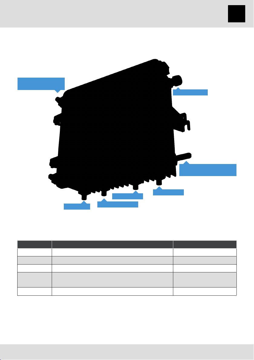
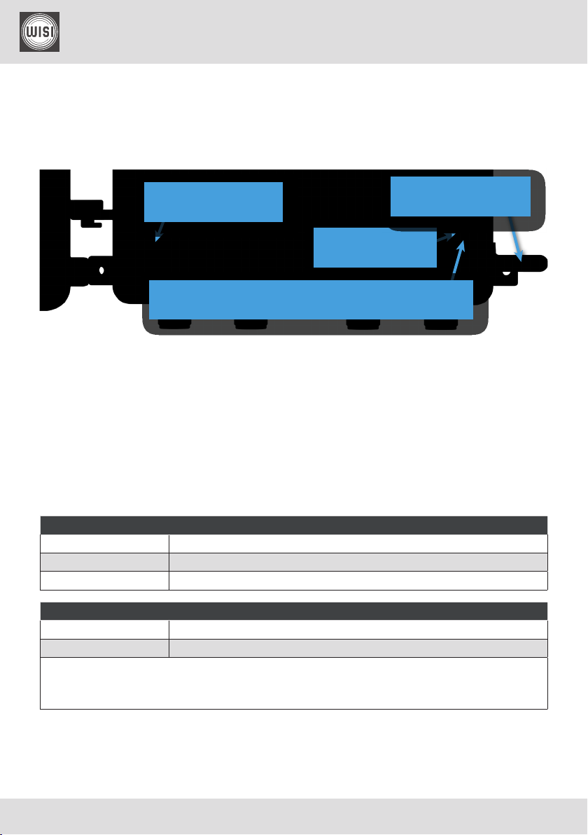
VX 52 B / VX 53 B series
RF amplifier - single output stage
1 Safety and warning notes
Please read the instructions before using the equipment.
Carefully inspect the device for any obvious damage. If it appears to have
been damaged, contact your WISI representative.
Do not use any equipment with noticeable damage!
1.1 ESD protection
This product contains electrostatic sensitive components.
These parts can be damaged or effectively destroyed by electrostatic dis-
charge (ESD) during unpacking, installation, removal, storage, or shipment
if incorrectly handled.
Please note that discharge might go unnoticed by a user.
Always take common anti-static precautions when handling the equipment.
1.2 Electrical safety
Risk of bodily injury from electric shock!
Failure to adhere to these instructions could result in personal injury and/or
damage to electrical components.
•The equipment must be grounded in accordance to local and national electrical
standards.
•The device is started up immediately when the power plug is inserted into the
mains socket. To turn off the power supply, the plug must be removed from the
socket. Never pull at the cable.
•The mains socket should be easily accessible. In the event of operational error, the
plug must be immediately removed from the socket.
•The power supply partition of the equipment as well as all coaxial interfaces carry-
ing remote power feeding contain dangerous voltages. All service or maintenance
work should be carried out by qualified personnel who can get assistance by con-
tacting the manufacturer’s agent.