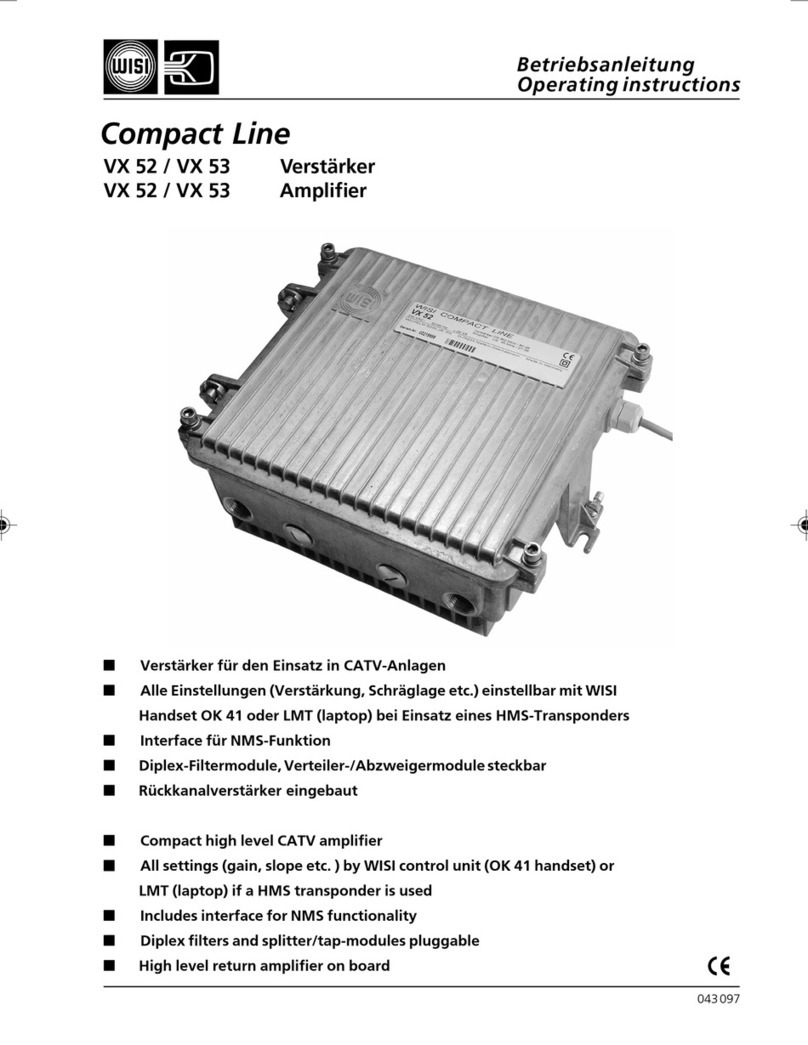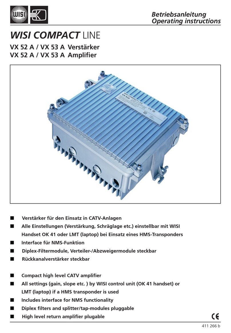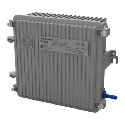
Sicherheitshinweise - bitte beachten!
Safety and installation notes – please observe!
Caution
The mains voltage must match the rated input
voltage of the unit (230 VAC).
Connecting cable — Lay the cable so that no-
one can trip over it.
— Lay the cable with a down-
ward loop so that any water condensing on it can
drip on the floor instead of running into the unit.
Selecting the installation location
Excessive temperatures will reduce the operating
lifetime of the unit. DO not install the unit directly above
or in the vicinity of radiators or heating systems where
it would be subjected to thermal radiation or oil vapours.
Moisture
Water dripping or splashing onto the unit will
damage it. If there is condensation on the unit, wait
until this has evaporated before switching the unit
on.
Caution – danger!
In accordance with EN 50 083-1, the satellite
antenna system must comply with the safety
requirements with respect to grounding, potential
equalisation, etc.
Service work
Service work may be carried out only by qualified
personnel. Always disconnect the supply voltage
before starting any such work.
Bemassung / Dimensions
LNB-Versorgungs-Spannung liegt an allen Eingängen gleichzeitig an / LNB power
applied on all inputs simultaneously
Auswahl mit Handset zwischen / Selection of
with handset
– 14 VDC
– 14 VDC - 22 kHz
– 18 VDC
– 18 VDC - 22 kHz
Anlagenbeipiele / Applications
Achtung
Die angegebene 230 VAC-Betriebsspannung muß
mit der Netzspannung übereinstimmen.
Anschlußkabel — Stolperfrei verlegen.
— mit einer Schlaufe verlegen,
damit bei Kondenswasser -Schwitzwasserbildung
kein Wasser ins Gerät läuft sondern auf den Boden
abtropft.
Aufstellungsort auswählen
Zu starke Hitzeeinwirkung oder Wärmestau beein-
trächtigen die Lebensdauer. Nicht direkt über oder in
der Nähe von Heizungsanlagen o.ä. montieren, wo
das Gerät Hitzestrahlung oder Öldämpfen ausgesetzt
ist.
Feuchtigkeit
Tropf- oder Spritzwasser schadet dem Gerät. Bei
Kondenswasserbildung warten, bis die Feuchtigkeit
abgetrocknet ist.
Achtung Lebensgefahr!
Nach EN 50 083-1 muß die Satelliten-Anten-
nenanlage den Sicherheitsanforderungen bezüg-
lich Erdung, Potentialausgleich etc. entsprechen.
Servicearbeiten
Dürfen nur von autorisiertem Fachpersonal durch-
geführt werden. Vor Beginn der Servicearbeiten die
Betriebsspannung abschalten.
OM 0..OM 0..
DM 02
OUT
470-862
MHz
IN-4 IN-5
Netzteil
Power supply
Alimentation
IN-1
+5VDC
110mA
IN-3
Module anschrauben
Tighten moduls / Visser les modules
OM 12 OM 12
230 VAC
(B)
(A) (A)
Modul 1 Modul 2 Modul 3
OM 12
IN-6IN-2
Einbau OM 12...Module
Installation OM 12...moduls
Hinweis: Wird Modul 1 eingebaut, muß Platine
(B) gesteckt bleiben. Werden weitere OM
12...Module 2-3 eingebaut, entfällt Platine (B).
Die zwei Schrauben (A) am Gehäusedeckel
lösen und Deckel abnehmen. Modul einsetzen,
anschrauben und anschließen. Deckel an-
schrauben und Einstellungen mit Handset OK
41A vornehmen.
Note: If only module 1 is installed, board (B)
must be left in place. If further OM12...modules
(2-3) are installed, board (B) is no longer
required. Loosen the two screws (A) on the
cover and remove the cover. Insert the module,
screw it down and connect it.
Fit and secure the cover and make the
necessary settings with the handset OK 41A.
Werkseitige Einstellungen/ Factory settings
Ausgangsdämpfung / Output attenuator
0 dB
OM12...
SAT-ZF-Eingangsfrequenz / Ausgangskanal
SAT IF input frequency / Output channel
1214 MHz 21 Ch
1244 MHz 23 Ch
Spannungsfrei schalten!
Switch off power supply!
DM 16
OC 41
Zur Verteilanlage
To distribution system
470-862 MHz
Single Universal LNB
OC 44
QUADRO Universal LNB
OM 0..
Netzteil
Power supply
LNB power
230 VAC
Modul 1 Modul 2 Modul 3
DM 13 DM 13
H/LB
V/LB
