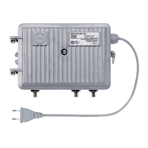
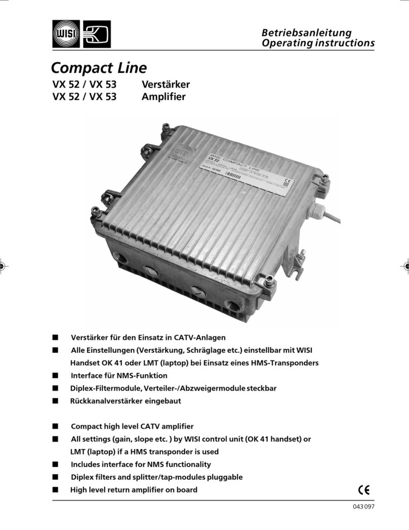
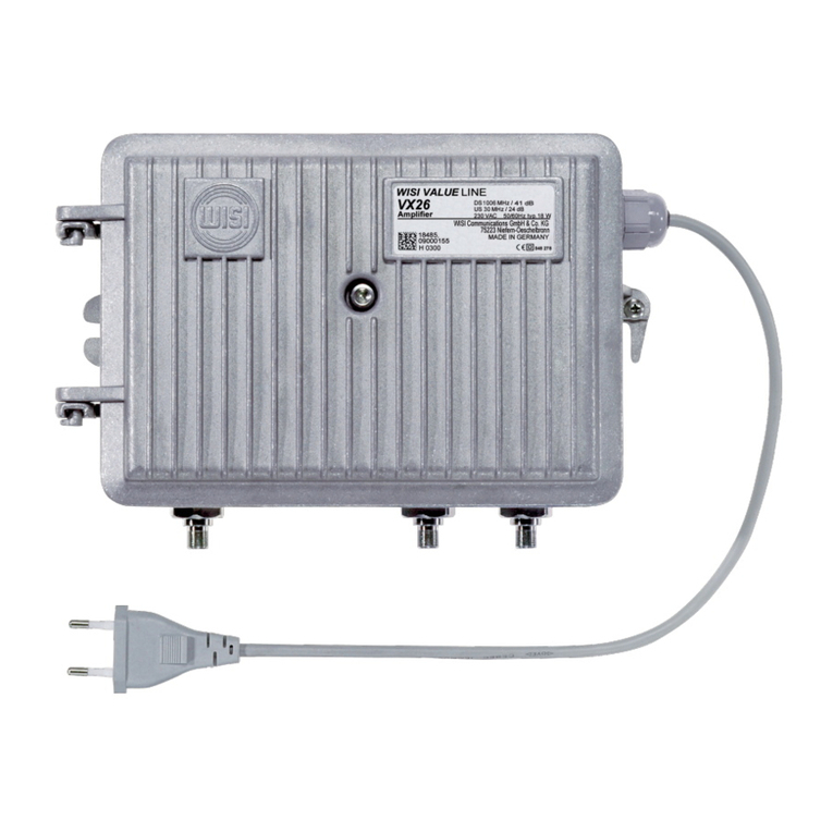
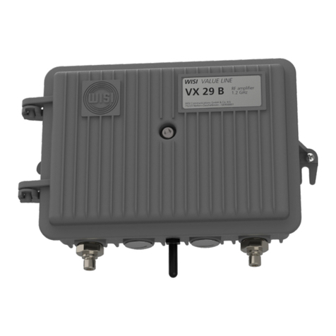
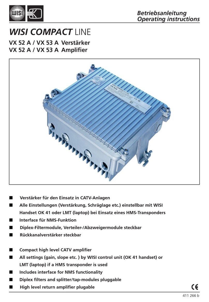
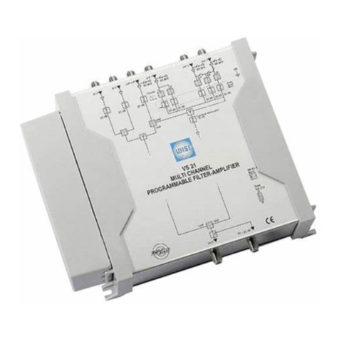
Wisi VX 24 User manual

- 1 -
043 062
Betriebsanleitung
Operating instructions
WISI VALUE LINE
VX 24
VX 25
Super compact housing
All settings (gain, slope etc.) programmable with
handset OK 41A or HMS transponder
High output level
High gain
Return path module active / passive
Sehr kompaktes Gehäuse
Alle Einstellungen (Verstärkung, Schräglage usw.)
mit Handset OK 41A oder HMS-Transponder
Hoher Ausgangspegel
Hohe Verstärkung
Rückwegmodul aktiv / passiv
Ortsgespeister Verstärker /
Local feed distribution amplifier
Ferngespeister Verstärker /
Remote feed distribution amplifier

- 2 -
Bemassung / Anschlüsse - Dimensions / Connectors
Die Verstärker werden ohne Gehäusekuppler ausgeliefert.
Sicherheitsanforderungen!
Servicearbeiten dürfen nur vom Fachpersonal durchgeführt wer-
den. Netzspannungsführende Teile beachten !
Netzbetriebene Geräte dürfen im Freien nur in einem isolierten
Wetterschutzgehäuse betrieben werden.
The amplifiers are supplied without glanded cable connec-
tors.
Safety instructions!
Services and repairs should only be carried out by experts.
Pay attention to live parts or wires!
Notice: In case the amplifier will be installed outdoor, please
provide sufficient weather protection according the local power
authorities requirement.
236,8
89,2
145,2
213,6
VX 24 - 230 VAC
input output 2 output 1

- 3 -
Steckplätze der Module - Plug-in slots of modules
Zubehör / Accessories
7,5A
XE 20A / 0300
XE 20A / 0650
Universal plug in
for ex. XE 51 / XE 52
Handset
XE 20A / 0300
XE 20A / 0650
Power supply
TP IN TP OUT
VX 27A
Einspeisung
Injection
IN
Jumper
input output2 output1
7,5A
7,5A
1
2
34
5
6
65 VAC
GND
65 VAC
Splitter
Fernspeisespannung
Remote feed voltage
Power LED
VT 24
Tx RX
VT 24
Fernspeisung
Remote feed
Power LED
oder / or
Bestellinformationen / Ordering informations
No. Type VX 24 / 25 Zubehör
werkseitig separat bestellen
ex factory Accessory
separate order
(1) XE 20A / 0300 Diplex-Filter Jumper X
XE 20A / 0650 Diplex filter
(2) Universal plug-in Jumper X
(3) VX 27A — X
Rückwegmodul aktiv
Return path module active
(4) XE 20A / 0300 Diplex-Filter Jumper X
XE 20A / 0650 Diplex filter
(5) Jumper Jumper —
(6) 3-dB-Splitter lose beigelegt —
3 dB splitter enclosed separately
Abzweiger/Splitter
XM 25-0082 / 8.5 dB — X
XM 25-0131 / 13 dB — X
Handset OK 41 / OK 41A
VT 24 Transponder

- 4 -
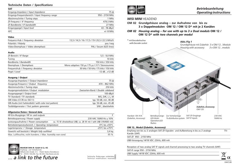
Technische Daten / Specifications
Inbetriebnahme
1. Deckelschrauben lösen und Deckel aufklappen.
2. Gehäusekuppler in die Anschlüsse IN und OUT einschrauben.
3. Innenleiter festschrauben.
4. Für VX 24 gilt: Netzstecker einstecken.
5. Für VX25 gilt: Fernspeisespannung mit Stecksicherungen auf die
HF-Anschlüsse am Ein- und Ausgang aufschalten*.
6. Verstärker lt. Pegelplan mit Dämpfer und Entzerrer einpegeln.
7. Deckel schließen und Deckelschrauben festziehen.
Initialisation
1. Loosen the cover screws and open the cover.
2. Screw the glanded connectors into the IN and OUT terminals.
3. Screw down the inner conductors.
4. For VX 24: insert the power plug in the AC wall outlet.
5. For VX 25: connect the remote power via plug-in fuses to the RF
connectors at the input and output*.
6. Adjust the amplifier with attenuator and equalizer in accordance
of the level plan.
7. Close cover and tighten the cover screws.
* Einspeisung auch über Strom-
versorgungskabel, das durch
die PG 9-Buchsen auf den
Steckanschluss der Grund-
platine aufgesteckt wird oder
direkt am Fernspeiseanschluß
des Netzteiles.
* Power can also be connected
via a power supply cable inser-
ted through the PG 9 gland
and connected to the terminal
of the main board or directly
at the remote feed connector
of the power supply.
Inbetriebnahme - Initialisation
Vorwärtskanal / Downstream
Frequenzbereich abhängig vom Diplexfilter / Frequency range determined by diplex filter 47 (85)-862 MHz
Verstärkung / Gain Einzelausgang / Single output 36 dB
Ausgangspegel für CENELEC 42 Kanäle Einzelausgang / Single output @109 dBµV, flat
Output level for CENELEC 42 Ch. - CSO > 64 dB
- CTB > 60 dB
Ausgangspegel für CENELEC 42 Kanäle Einzelausgang / Single output @112 dBµV,9 dB slope
Output level for CENELEC 42 Ch. - CSO > 63 dB
- CTB > 60 dB
Dämpfungssteller / Attenuator 0.5-dB-Schritte / steps 0-15 dB
Entzerrer / Equalizer 0.5-dB-Schritte / steps 0-15 dB
Interstage / Interstage Dämpfer / Attenuator 0 / 5 dB
Entzerrer / Equalizer 0 / 7 dB
Rauschmaß / Noise figure < 7 dB
Rückflußdämpfung (Ein -Ausgang) / Return loss (input- output) 18 dB -1.5 dB/oct.
Meßbuchse / Test socket - 20 dB
Rückkanalverstärker Modul VX 27... /...Return path amplifier module VX 27.../...
Frequenzbereich abhängig vom Diplexfilter / VX 27A 5 - 65 MHz
Frequency range determined by diplex filter VX 27A / 0180 18 - 65 MHz
Verstärkung / Gain 30 dB
Dämpfungssteller / Attenuator 1 dB steps 0-30 dB
wenn Interstage Dämpfer und Entzerrer = 0 dB / if interstage attenuator and equalizer = 0 dB 4-30 dB
- 5 -
Entzerrer / Equalizer 0.5-dB-Schritte / steps 0-10 dB
Ausgangspegel / Output level 2. Ordnung / 2nd order 114 dBµV
3. Ordnung / 3rd order 114 dBµV
ICS (Ingress Control Switch) 0 / 8 / >45 dB
Einspeise-Buchse / Injection socket - 20 dB
Meßbuchse / Test socket - 20 dB
Allgemeines / General
Betriebsspannung / Operating voltage VX 24 180-265 VAC / 50/60 Hz
VX 25 27-65 VAC
Leistungsaufnahme mit Rückwegverstärker / Power consumption incl. upstream amplifier <13 W
Anschlußtechnik / Connectors PG 11
Fernspeisestrom / Remote power current Eingang / Input < 6A
Ausgänge / Outputs < 3A
Impedanz / Impedance 75 Ω
Betriebstemperaturbereich / Ambient temperature -20 °C...+55 °C
Lagertemperatur / Storage temperature -25 °C...+75 °C
Max. Luftfeuchte, nicht kondensierend / Max. humidity, non condensing 95 %
Schutzart / Protection class IP 66
Blitzschutz RF-Anschlüsse / Lightning protector RF connectors 4 kV
Blitz- / Transientenschutz Stromversorgung / Lightning protector operating voltage 2 kV
EN 61000-4-5 1.2/50 µs pulse
Betriebsanzeige / Operation indicator LED green
EMV gemäß / EMC according to EN 50083-2
Zubehör / Accessories
VX 27A / VX 27A 0180 - HP 18 MHz Rückkanalverstärker aktiv / Return path amplifier active
VX 27 P (auf Anfrage, on request) Rückkanalmodul passiv / Return path module passive
XE 20A / 0300 Diplex-Filter 30 MHz / Diplex filter 30 MHz
XE 20A / 0650 Diplex-Filter 65 MHz / Diplex filter 65 MHz
Abzweiger / Splitter XM 25...
-Frequenzbereich 5-862 MHz
-XM25 / 0082 8.5 / <2.51) dB
-XM25 / 0131 13 / <11) dB
ZG 01 Adapter PG 11 - 5/8" / Adapter PG 11 - 5/8"
OK 41A Handset / Handset
1) Durchgangsdämpfung / Thru loss
Downstream - Anzeigen und Einstellungen mit Handset / DS display and settings with handset
- Eingangs-Entzerrung Input Equalizer 0 dB... 15 dB. 0,5-dB-Schritte, 0.5 dB steps.
- Eingangs-Dämpfung Input Attenuator 0 dB... 15 dB. 0,5-dB-Schritte, 0.5 dB steps.
- Interstage-Dämpfung Interstage Att. 0 / 5 dB
- Interstage- Schräglage Interstage slope 0 / 7 dB
Upstream
- Dämpfung Up. Attenuation 0 dB... 30 dB. 1-dB-Schritte,1 dB steps.
- Schräglage Up. Slope 0 dB... 10 dB. 0,5-dB-Schritte, 0.5 dB steps.
- Ingress Controll Switch ICS Up. ICS
Low 0 dB

- 6 -
universal
plug in
Handset
interface
equalizer attenuator
fuse
VX24: 230 V AC
VX25: 27 - 65 V AC
AC
12 VDC
5 VDC
amp.
equalizer
(switchable)
0/9 dB
attenuator
(switchable)
0/5 dB
Transponder
interface
m
C
power
amp.
HP/LP
testpoint
-20 dB
splitter/tap
(plugable)
AC-
coupling
fuse
output 1
output 2
input
AC-
coupling
fuse
testpoint
-20 dB
HP/LP
equalizer amp. att amp. ICS HP
Injection
point
-20 dB
AC
65 VAC
GND
65 VAC
return module VX 27A ...
Blockdiagram mit aktivem Rückkanalverstärker-Modul VX 27 A
Block diagram with active return path amplifier module VX 27A

- 7 -
Anschluß
Handset an Buchse "RJ-11" einstecken. Betriebsspannung anschließen.
Parameter-Menü
Tasten. — Parameter wählen.
Taste. — Weiter zum Parameter-Untermenü.
Taste. — Zurück.
Parameter-Untermenü
Tasten. — Anzeige oder zu ändernden Wert wählen.
Cursor steht unter dem Wert z.B. 89
Tasten. — Wert ändern.
Parametereinstellung mit Handset (Zubehör)
Bedienschritte Display/Untermenü Einstellungen
Downstream Downstream Mit UP/DOWN-Taste und mit bestätigen.
Upstream Upstream Upstream-Menü: nur wenn VX 27A gesteckt ist.
Sys. Settings Sys. Settings
Bei den Einstellungen zeigt ein *an, daß die Einstellung geändert wurde.
Downstream
Eingangs-Entzerrung Input Equalizer 0 dB... 15 dB. In 0,5 dB-Schritten einstellbar.
Eingangs-Dämpfung Input Attenuator 0 dB... 15 dB. In 0,5 dB-Schritten einstellbar.
Interstage-Dämpfung Interstage Att. 0 / 5 dB
Interstage-Schräglage Interstage slope 0 / 7 dB
Upstream
Dämpfung Up. Attenuation 0 dB... 30 dB. In 1 dB-Schritten einstellbar.
Dämpfung <4 dB einstellbar, wenn im Downstream-Menü >Interstage Att.< oder >Interstage slope<
eingestellt wurde.
Schräglage Up. Slope 0 dB... 10 dB. In 0,5 dB-Schritten einstellbar.
Ingress Controll ICS Up. ICS
Switch Low 0 dB
Pad 8 dB
High >45 dB (off)
Sys. Settings
Die Parameter eines eingestellten VX 2... können auf das Handset OK 41A abgespeichert und von dort auf
weitere VX.2... übertragen werden.
Einstellungen Auswahl: Speichern/Zurückspielen Ja oder Nein
- speichern
Save Val. > OK41A yes, save - no, not save
- zurückspielen Res. Val. < OK41A
yes, restore - no, not restore
Speichern
Speichern Save data to EEPROM Taste so oft drücken, bis
„Save Data to EEPROM“ erscheint.
Left Right
Down
Up
W
ISIVX24
1. 0 0
V

- 8 -
Connection
Plug the handset into socket "RJ-11". Connect the supply voltage.
Parameter menu
keys — Select parameter.
key — Open parameter sub-menu.
key — Back.
Parameter sub-menu
keys — Select display or value to be changed.
Cursor stands under the value, e.g. 89
keys — Change the value.
Left Right
Down
Up
W
ISIVX24
1. 0 0
V
Parameter settings with handset (Accessory)
Operation steps Display/sub-menu Settings
Downstream Downstream Select with keys and confirm with .
Upstream Upstream Upstream menu is available only if
Sys. Settings Sys. Settings VX 27A is plugged in.
An asterisk (*) in the settings shows that a setting has been changed.
Downstream
Input Equalizer Input Equalizer 0 dB... 15 dB. 0,5 dB steps.
Input Attenuator Input Attenuator 0 dB... 15 dB. 0,5 dB steps.
Interstage Attenuator Interstage Att. 0 / 5 dB
Interstage slope Interstage slope 0 / 7 dB
Upstream
Up. Attenuation Up. Attenuation 0 dB... 30 dB. 1 dB steps.
Up attenuation <4 dB adjustable, when Interstage slope or Interstage -Att. are set in downstream menu.
Up. Slope Up. Slope 0 dB... 10 dB. 0,5 dB steps.
Ingress Controll ICS Up. ICS
Switch Low 0 dB
Pad 8 dB
High >45 dB (off)
Sys. Settings
The parameters of an VX 2...which has been set can be saved to the memory of the handset OK 41A and
transferred from there to other VX 2... systems.
Settings Select: Save or Restore, Yes or No
– Save
Save Val. > OK41A yes, save – no, not save
– Restore Res. Val. < OK41A
yes, restore – no, not restore
Savings
Save Save data to EEPROM Press several times until the display shows:
"Save Data to EEPROM“.
07.06
This manual suits for next models
1
Table of contents
Other Wisi Amplifier manuals

Wisi
Wisi VX 56 B Series User manual

Wisi
Wisi PROSWITCH DY 40 User manual

Wisi
Wisi VX 52 B Series User manual

Wisi
Wisi MIDI Series User manual

Wisi
Wisi VX 56 B Series User manual

Wisi
Wisi VX 52 User manual

Wisi
Wisi VX 29 B Series User manual

Wisi
Wisi DY 90 User manual

Wisi
Wisi VX 12 V 2220 User manual

Wisi
Wisi VX 52 B Series User manual