Wisniowski MIDO 600 User manual

DRIVE UNIT FOR GARAGE DOORS
MIDO
Assembly and Operating
Instructions
MIDO 600
MIDO 800
MIDO 1000
EN
DE
FR
RU
Technical description
Assembly and Operating Instructions
Drive unit for garage doors / PART 2
Technical documentation - go to PART 1 (EU - 1/2)
Technische Beschreibung
Montage und Bedienungsanleitung
Antrieb für Garagentore / TEIL 2
Technische Dokumentation - siehe TEIL 1 (EU - 1/2)
Descriptif technique
Notice de Montage et de Fonctionnement
Automatisme pour les portes de garage
/ PART 2
Dossier technique - voir PART 1 (EU - 1/2)
Техническое описание
/ 2
Техническая документация - смотри ЧАСТЬ 1 (EU - 1/2)
(EU - 2/2)
CS
Technický popis
Návod k instalaci a obsluze
Pohon pro garážová vrata / ČÁST 2
Technická dokumentace - přejděte na ČÁST 1 (EU - 1/2)
SV
Teknisk beskrivning
Montering och bruksanvisning
Drivenhet för garageport / DEL 2
Teknisk dokumentation - gå till DEL 1 (EU - 1/2)
– page 2
– Seite 9
– page 17
– strana 32
– sida 39
– 24

Assembly and Operating Instructions – Drive unit for garage doors MIDO
2
EN
IIiO/MIDO/07/2012/ID-93341 Technical Description
TABLE OF CONTENTS:
1. General information ........................................................................................ 2
2. Terms and definitions according to the norms ............................................... 2
3. Symbols meaning ............................................................................................ 2
4. Build description and technical specification ................................................ 2
4.1. Application and designation ................................................................ 2
4.2. Safety guidelines ................................................................................... 2
5. Installation guidelines ..................................................................................... 2
6. Required installation conditions ..................................................................... 2
7. Installation instructions .................................................................................... 3
7.1. Installation sequence ............................................................................. 3
7.2. Photocells circuit diagram ..................................................................... 3
7.3. Bell-push circuit diagram ....................................................................... 3
7.4. El3Q radio receiver circuit diagram ..................................................... 3
7.5. Drive installation errors .......................................................................... 3
8. Environment protection ................................................................................... 3
9. Dismantling the drive ....................................................................................... 4
10. Operation issues ............................................................................................. 4
11. Technical parameters ...................................................................................... 4
12. Door instruction manual .................................................................................. 4
13. Drive adjustment .............................................................................................. 5
13.1. Overload adjustment ............................................................................. 5
14. Controller ......................................................................................................... 5
14.1. The intended use and operation principle ........................................... 5
14.2.Controller installation sequence ........................................................... 5
14.3.Controller programming ........................................................................ 5
15. Routine maintenance instructions ................................................................... 6
16. Warranty terms ............................................................................................... 6
17. The equipment of the MIDO drive ................................................................. 7
18. FAQ .................................................................................................................. 8
[A000001] 1. GENERAL INFORMATION
The door can be installed and adjusted by at least a COMPETENT person.
[A000019] This Assembly Instruction is intended for professional installers or
other competent persons. It provides necessary information on safe installation
of the drive unit.
[A000020] The drive and its components have to be installed in line with the
drive Installation & Operation Manual supplied by „WIŚNIOWSKI” ltd. Only
original fixing parts, supplied with the drive, may be used to install the drive.
Read this manual before proceeding with the installation works. Read this man-
ual carefully and follow the guidelines in it. Correct drive operation to a large
degree depends on its correct installation.
[A000021] Drawings may differ in build details. When necessary, such details
are presented in separate drawings. This instruction provides the necessary in-
formation on a safe installation, usage and maintenance of the drive.
When proceeding with the installation, follow the safety rules on the following:
installation works, fitting works, and usage of electric tools applicable to the
installation method selected. Current norms, regulations and the construction
documentation should be followed too. In maintenance protect the drive from
plaster, cement and gypsum spalls likely to leave stains.
[A000022] Assembly and Operating Instruction is intended for the drive owner.
When the installation is complete, this manual should be issued to the owner. It
should be kept carefully and be protected against damage. No elements of the
drive may be modified or removed. Doing so may influence its safe operation.
Changing drive subassemblies is forbidden.
[A000042] When installing the drive, follow the guidelines of “WIŚNIOWSKI”
sp. z o.o. sp. k., the manufacturer of both the drive and the accessories. In con-
necting the drive, only original subassemblies may be used.
[D000136] This book covers installation of the drive with standard
and optional accessories. Standard and optional equipment rang-
es are listed in the commercial offer.
[A000023] WARNING: Read this manual carefully and
follow the instructions. It provides the necessary infor-
mation on a safe installation, usage and maintenance of
the drive. Keep this instruction with due care.
[A000037] 2. TERMS AND DEFINITIONS ACCORDING TO THE NORMS
Meaning of safety pictograms used in this book:
Important - a sign to draw your attention.
Information - a sign meaning an important bit of information.
Reference - a sign referring you to another place in this book.
Professional installer - a competent person or business unit who/which of-
fers door installation and enhancement services (as in EN 12635).
Competent person - a person with a relevant training record, possessing
skills based on his/her knowledge and experience, and familiar with the nec-
essary instructions to proceed with the installation properly and safely (as in
EN 12635).
Owner - a natural or legal person entitled to dispose of the door and responsi-
ble for its operation and usage (as in EN 12635).
Report book – a book with main data of a particular door and blanks for
inspections, tests and maintenance entries, as well as repairs and modifications
reports (as in EN 12635+A1).
[D000137] 3. SYMBOLS MEANING
Rs – unlocking in sectional doors
Ru – unlocking in up-and-over doors
Pw – white wire
Pr – red wire
Pg– green wire
Pb – brown wire
Py – yellow wire
[A000052]
- option - manual - automatic
[D000138] 4. BUILD DESCRIPTION AND TECHNICAL SPECIFICATION
The drive makes a set with a slide rail of a relevant length which is necessary
for its correct operation. It is mounted on the end of a steel slide rail. The rail is
equipped with a driving chain which drives a catch. The catch is integrated with
a door. The operator drives the door via an arm fastened to the chain holder
from one side, and to the door leaf top part on the other side. The drive is pro-
tected with overload switches; when the door leaf meets resistance on the way,
the drive will stop and reverse.
[D000139] 4.1. APPLICATION AND DESIGNATION
The drive is used to open automatic sectional and up-and-over garage doors,
with dimensional limits specified in the commercial offer, as well as operation
time limits and technical specifications from this instruction. The drive is intended
for dry rooms, and it may not be applied outdoors.
[B000004] 4.2. SAFETY GUIDELINES
Minimum safety levels provided in the door closing edge as required by
PN-EN 13241-1.
Door activation
method
Usage
Trained door
operators (private
premises)
Trained door
operators (public
premises)
Not trained
door operators
(public pre-
mises)
Deadman control with
the view of the door
(the Totmann version)
Push-button control
without electrical
latching
Key-switch control
without electrical
latching
Unacceptable
Pulse control with the
view of the door
(the Automatik version)
Pulse control without the
view of the door
(the Automatik version)
Automatic control
(the Automatik version
– automatic closing)
– safety bar - obligatory
– photocells barrier - obligatory – photocells barrier - optional
[A000024] 5. INSTALLATION GUIDELINES
Read these guidelines before proceeding with installing and starting up the
drive. Follow the drive installation and usage guidelines for a long and efficient
usage. The order of the installation steps must be followed too.
[A000025] 6. REQUIRED INSTALLATION CONDITIONS
The drive should be applied and operated in line with its designation. A selec-
tion of the operator must be based on the way the door is driven.
[B000026] The room where the drive fitting is planned should be finished
completely (plastered walls, finished floor). It should be also dry and free of
any harmful chemicals.

Assembly and Operating Instructions – Drive unit for garage doors MIDO
3
EN
Technical Description IIiO/MIDO/07/2012/ID-93341
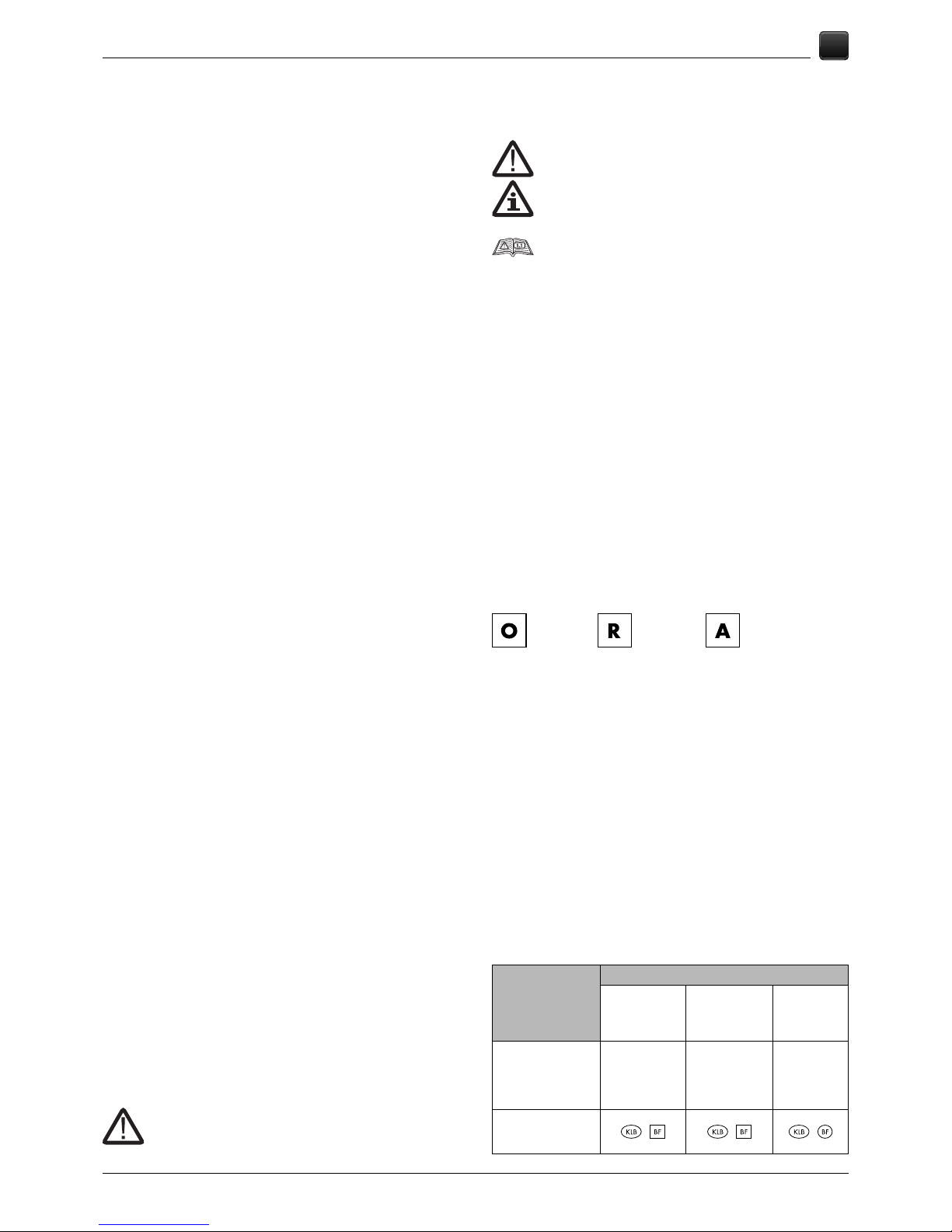
Installing the operator in a room which requires more
working (plastering, gypsum works, grinding, painting,
etc.) is not allowed. Installing the drive in an explosion
risk area is not allowed.
A proper garage ventilation should be provided (drying). The drive is to be
installed by a professional installer or other competent person only and in line
with this instruction.
[D000140] The required header capacity is >500N.
[B000027] Safety conditions
• The wiring system and the electric shock protection installations are defined
by current norms and regulations.
• The drive feed circuit should be equipped with a cut-off protection, a residual
current circuit-breaker, and an overcurrent protection.
• The drive feed system should be executed as a separate electrical circuit.
• Obligatory grounding should be made in the first place.
• When installing the drive, the wires delivered by “WIŚNIOWSKI” sp. z o.o.
sp.k. with the drive should be used.
• Electrical wiring must be executed according to local regulations.
• Only a qualified installer my perform electrical works.
• The door and the drive set must comply with PN-EN 12453, and PN-EN
12604 standards.
• MIDO drive complies with the following EU directives:
• Low Voltage Directive 2006/95/EC
• Machine Directive 2006/42/EC
• Electromagnetic Compatibility Directive 2004/108/EC
• Radio and Telecommunications Terminal Equipment Directive 1999/5/EC.
• [C000081] The drive must not be installed in an explo-
sion risk environment. Presence of flammable gases
and vapours is a major risk factor.
• [A000026] Keep the packaging (plastics, polystyrene,
etc.) out of the reach of children.
[D000144] 7. INSTALLATION INSTRUCTIONS
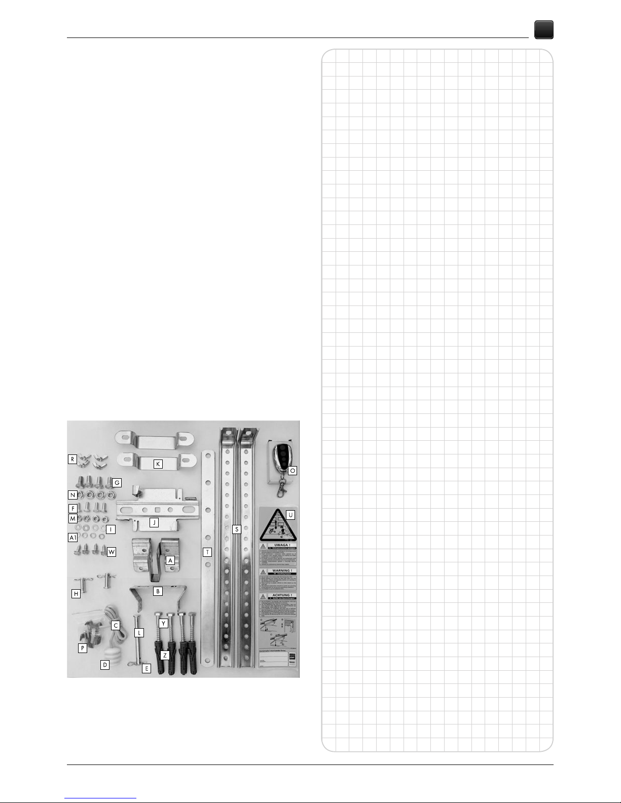
Preparatory activities include preparation of the wiring system. A rough layout of
the device components and wire arrangement is presented in figure 2.
Electrical wiring must be made by local regulations.
Only a qualified installer my perform electrical works.
[D000145] Garage ceiling must provide safe installation of the drive. If the
ceiling is too light or too high, or the drive mass exceeds 20 [kg], then it should
be mounted on a support structure adequate to room conditions. Mounting the
door or the drive fixing elements in a way that allows their dislocation during
operation is not allowed.
[C000084] Correct drive operation to a large degree depends on its correct
installation. On an extra order, “WIŚNIOWSKI” sp. z o.o. sp. k. performs instal-
lation itself or recommends authorised installation companies. Only installation
and maintenance done by competent persons or companies, in line with this
instruction, may guarantee safe and intended operation of the drive.
[D000146] Before drive installation, make sure that the door the drive is mount-
ed on has been mounted and adjusted correctly and opens and closes easily.
Also dismantle the fixing parts and the drive components which do not require
power supply.
The drive must not be installed with a non-operational
door. Disconnect the drive from power source before
proceeding with the installation works. Also a battery
power supply should be disconnected if it has been delivered.
[C000085] Correct operation of the door and the drive unit to a large extent
depends on the drive correct installation. To avoid malfunctioning, premature
wear or warranty loss of the drive, this instruction has to be strictly followed.
[D000147] The drive is delivered with fixing elements to apply to concrete; for
walls made of other materials different fixing elements may be required.
[C000086] If a wicket door is fitted in the garage door you must check if the
fixed elements do not protrude into a public pavement or road.
[D000259] 7.1. INSTALLATION SEQUENCE
Fig.3. Install the catch plate for the “Ru” up-and-over door leaf. The catch
plate is mounted in the middle of the door leaf.
Fig.4. Install the catch plate for the sectional door. The catch plate is
mounted in the middle of the door leaf. In the sectional doors with
the top panel cut, the leaf catch plate is delivered with the door.
Fig.4.7 Acceptable installation of a sectional door leaf catch plate; fixing
elements are not delivered with the drive.
The presented holes level for the door leaf catch plate
applies to doors manufactured by “WIŚNIOWSKI”
sp. z o.o. sp. k., in case of other doors the height
should be decided on by the client.
Fig. 5-6. Mark out installation holes for the header catch - in the header.
Fix the header catch to the header 20-150[mm] above the shaft or
above the door leaf catch plate (as offered by a free installation
space). Fix the metal slide rail to the catch with the “L” bolt. Fix
the drive to the slide rail with a “K” catch. Tighten with a 2[Nm]
torque. Fix the drive catch as close to the engine as possible, if
there is enough space.
Important: Make sure the slide rail is levelled towards
the door shaft.
Make sure that the “S” slide rail suspension brackets are fixed well
to the ceiling. Fix the slide rail with the dedicated “J” metal suspen-
sion bracket (depending on “v1” or “v2” design version).
Fig.3.1c, Fig.7. Connect the door leaf with the drive by means of the connec-
tion strip.
Fig.8. Fasten the coupling cord. The cord should be fastened at the height
below 1800 [mm] from the floor. Unlock the drive by pulling the
cord, attempt to open and close the door by hand. Make sure there
is no resistance between the door panel and the drive guide.
Fig.9. Mount a door leaf catch plate on the door and the “Rs” unlocking.
Connect the door leaf with the drive by means of the connection
strip.
Fig.8. To open the garage door in a blackout the drive must be unlocked
with the cable. The drive is provided with a function of the hoist
disengagement with a cable. Pull the cable to unlock the garage
door drive. To reengage the drive shift the lever, the cable is fixed
on, back to the original position. When the garage door is not
fitted with a wicket door, an external unblocking mechanism is
recommended. The cable handle should be mounted not higher
than 1800 [mm] above the floor.
• [D000273] Unlocking is not allowed when the drive is
operating, as this can cause permanent damage to the
drive. Pulling the drive unlocking cable with the whole
body weight is not allowed.
• [D000274] Take special care when unlocking the drive
manually: the opened garage door can fall if springs
are weak or broken or if the door is not balanced in
the right way.
[D000149] 7.2. PHOTOCELLS CIRCUIT DIAGRAM
Photocells connection to the control panel is presented in fig.19.
[D000172] 7.3. BELL-PUSH CIRCUIT DIAGRAM
Bell-push connection to the control panel is presented in fig.29.
[D000151] 7.4. El3Q RADIO RECEIVER CIRCUIT DIAGRAM
Radio receiver connection to the control panel is presented in fig.39.
[D000260] 7.5. DRIVE INSTALLATION ERRORS
Errors may occur when installing the drive, but they are easy to avoid when the
following steps are taken:
• the drive slide rail mounted and balanced properly, in line with data found
in this instruction,
• correct drive supply voltage,
• unlocking mechanism adjusted correctly,
• all connections parts tightened well.
Disregarding these basic recommendations may cause malfunctioning, damage
or warranty loss of the door.
[A000027] Extra requirements
On completing the installation, check if the door has a standard CE rating
plate, provide it if not. When you verify the drive operates correctly, submit
the drive Assembly and Operating Instruction to the owner. Apply warning
stickers in a way they are stable, visible, and close to the door or the control
panel.
[A000008] 8. ENVIRONMENT PROTECTION
Packaging
Packaging components (cardboard, plastics, etc.) are classified as recyclable
wastes. Dispose of them according to relevant local regulations.
Scrapping
This product consists of various materials. Most of them are recyclable. Segre-
gate them first, and then deliver to a recycling plant.

Assembly and Operating Instructions – Drive unit for garage doors MIDO
4
EN
IIiO/MIDO/07/2012/ID-93341 Technical Description
Dispose of them according to relevant local regulations.
[A000009] Important: Recycling cuts raw material usage
and wastes volume.
[A000016] This product is marked with the crossed-out wheeled bin logo, in
line with the Waste Electrical and Electronic Equipment Directive 2002/96/
EC. When discarded as waste it may not be utilised together with household
wastes. The user is responsible for delivering it to an appropriate recycling plant
authorised by the manufacturer or local authorities.
[D000153] 9. DISMANTLING THE DRIVE
The drive should be disassembled in the reverse order to the assembly. First, the
drive power supply should be disconnected, while the door should be closed
and locked.
[D000154] 10. OPERATION ISSUES
The following basic conditions ensure longterm and smooth operation of the
drive:
• protection of the drive from such agents corroding varnish coats and metal
as: acids, lyes and salts,
• when finishing or maintaining a room the drive should be protected against
plaster, paints and solvents chipping,
• the drive should be opened in line with the instruction delivered with the
electric equipment,
• if lifting of the door experiences excessive resistance, the hinges adjustment
should be verified and if it is found faulty then hinges should be adjusted in
line with the door Assembly and Operating Instruction,
• if a wicket door is installed in a garage door then lifting is only allowed
when the wicket door is locked.
In case of electrically driven doors, where a lock or
a locking bolt is applied, installing a lock sensor or
a locking bolt sensor is recommended. Otherwise, if an
actuator is connected to the power network the locking bolt or the
lock should be blocked in an open position.
[D000261] 11. TECHNICAL PARAMETERS
• Controller supply voltage [VAC] : 220 – 240
• Rated power [W]:
MIDO 600 : 150
MIDO 800 : 150
MIDO 1000 : 150
• Drive supply voltage [VDC] : 24
• Operating temperature [°C] : -20/+40
• ED efficiency [%] : 30
• S3 class : intermittent running
• Correct humidity : <90%
• Drive power [W]:
MIDO 600 : 40
MIDO 800 : 50
MIDO 1000 : 50
• Opening and closing force [N]:
MIDO 600 : 600
MIDO 800 : 800
MIDO 1000 : 1000
[C000011] 12. DOOR INSTRUCTION MANUAL
• Do not obstruct the door movement area. The door
opens up vertically. Accordingly, no barriers may stand in the
way of opening or closing the door. Make sure that no persons,
especially children, or objects stand in the way of a moving
door.
Caution! Risk of accident.
• [C000026] No persons, cars or objects are allowed to stay in the
door clear opening when the door is opened. No stopping, walk-
ing, running or driving under a moving door is allowed.
• The door leaf must not be used to lift objects or persons. Children
should not be allowed to play with this equipment. Keep control
transmitters out of the reach of children.
Caution! Risk of accident.
• [C000042] This equipment is not intended for persons (includ-
ing children) of limited physical, sensory or mental ability, or per-
sons of no experience or knowledge of such equipment, unless
supervised or assisted by other persons responsible for their safety
and on condition that they follow this instruction manual. Children
should not be allowed to play with this equipment.
Caution! Risk of accident.
[C000012] Before the door is opened for the first time, it should be checked in
line with the Assembly and Operating Instruction.
Smooth movement and operation of the door prove its correct installation.
[C000027] Each time the door is about to be started, make sure that the lock or
door bolt is not in the closed position.
Starting the door is allowed only when the lock and/or door bolt
are in the open position.
• [C000076] WARNING: Do not obstruct the door leaf
movement area.
Make sure that no persons, especially children, or objects stand in
the way of a closing or opening door leaf.
• [C000077] No barriers may stand in the way of a door leaf.
Caution! Risk of accident.
• [C000078] Opening and closing the door with the drive may be
performed only when the door is within the operator’s sight. Door
in motion should be watched.
Caution! Risk of accident.
• [C000079] The door may be approached only when its opera-
tion (opening or closing) is finished. Approaching the operating
door is not allowed.
Caution! Risk of accident.
• [C000080] Remote control transmitters, transmitters or other con-
trol equipment to activate the door should be kept out of the reach
of children, to avoid unauthorised activation. Children should not
be allowed to play with this equipment. Transmitters should be
kept in dry places.
Caution! Risk of accident.
• [C000082] If a non-detachable feed cable is damaged, it should
be replaced with a cable or a set of cables of identical param-
eters, available from the manufacturer or from a specialist main-
tenance shop.
• [C000083] If the garage door is equipped with a wicket door, the
drive may start only when the wicket door is closed. Wicket door
has to be equipped with a limit switch.
• [D000141] Take special care when unlocking the drive manually:
the opened garage door can fall if springs are weak or broken or
if the door is not balanced in the right way.
Caution! Risk of accident.
• [D000142] Before any maintenance or inspection of a garage
door, disconnect the drive from power source. Also a battery
power supply should be disconnected if it has been delivered.
• [D000143] Do not obstruct the door or the drive movement area.
Do not put fingers or objects into the slide rail.
Caution! Risk of accident.
[D000262] Manually operated door:
To open the garage door in a blackout the drive must be unlocked with the
cable. The drive is provided with a function of the hoist disengagement with
a cable. Pull the cable to unlock the garage door drive (fig. 8).
To reengage the drive shift the lever, the cable is fixed on, back to the original
position. When the garage door is not fitted with a wicket door, an external
unblocking mechanism is recommended. The cable handle should be mounted
no more than 1800 [mm] above the floor.
• [D000273] Unlocking is not allowed when the drive is
operating, as this can cause permanent damage to the
drive. Pulling the drive unlocking cable with the whole
body weight is not allowed.
• [D000274] Take special care when unlocking the drive
manually: the opened garage door can fall if springs
are weak or broken or if the door is not balanced in
the right way.
[D000263] Electrically driven door:
Opening and closing the door by the drive is done by pressing the button on the
remote control transmitter.
[C000092] After finishing works, maintenance involving
the change of a floor level, or dismantling and reinstalla-
tion of a door, limit switches should be checked and re-
adjusted.

Assembly and Operating Instructions – Drive unit for garage doors MIDO
5
EN
Technical Description IIiO/MIDO/07/2012/ID-93341
[D000159] 13. DRIVE ADJUSTMENT
• When the installation is complete, movement parameters of the drive should
be verified, as well as function of the overload switch. When the door encoun-
ters a barrier 50 [mm] high, it should stop and reverse.
Caution! Risk of accident.
• Make sure that the drive interrupts the opening operation if the door is loaded
with a 20 [kg] mass fixed in the middle of the bottom door edge.
Caution! Risk of accident.
• Drive controller parameters should be regulated according to the controller
manual. Movement parameters of the door should be regulated in line with
the Assembly and Operating Instruction.
[D000264] 13.1. OVERLOAD ADJUSTMENT
• Once a month minimum movement parameters of the door and the drive
should be verified, as well as the overload switch function. When the door
encounters a barrier 50 [mm] high, it should stop and reverse. When limit
switches are adjusted, the drive self-regulates the overload rate (the overload
rate may be regulated manually, see the controller manual). The set overload
rate should correspond to the minimum force at which the door can accom-
plish a full opening/closing cycle. The dynamic force of the main closing
edge may not exceed 400 [N] acc. to PN-EN 12453.
• The door pressure and pull force should be set to such values that no ob-
jects are damaged and no persons hurt (see manual adjustment of overload
switches in the controller manual).
Caution! Risk of accident.
[D000265] 14. CONTROLLER
14.1. THE INTENDED USE AND OPERATION PRINCIPLE
Advantages of controller:
• Soft start & stop, and related increased door operational life.
• Control via remote controls with a dynamic variable codes for 433,92MHz
frequency or via control panel buttons.
• Automatic selection of operation parameters.
• Photocells.
• Automatic closing.
• Overload rate adjustment.
• LED based lighting.
• Digital display.
• Sequential door control.
• Simple installation and programming procedure.
Drive control is executed via programmed button transmitter (remote control).
Photocells are an additional safety element to be connected to the control sys-
tem. They improve protection against the door running over a vehicle, a person
or an object in the way of the door.
Automatic closing requires photocells, to protect the user (the door will not
close when a barrier appears in the way). It also requires activating the function
in the controller.
Overload force is a necessary element to protect objects staying within the
door opening against crushing; it also protects from damage the engine and the
whole driving mechanism. The dynamic force of the main closing edge may not
exceed 400 [N] acc. to PN-EN 12453.
[D000266] 14.2. CONTROLLER INSTALLATION SEQUENCE
1. Make sure that the operator with its equipment is mounted correctly and that
its activation is not dangerous for the environment.
2. Switch the main drive supply on.
3. Find out the top and the bottom positions of the limit switch.
4. Activate the automatic opening and closing cycle to allow self-regulation of
the overload force. The dynamic force of the main closing edge may not
exceed 400 [N] acc. to PN-EN 12453.
5. The closing limit switch should adjusted to ensure a free door connector lock-
ing to the chain fitting, when the door is closed by hand (fig.8).
6. Check if the switches do switch off the drive.
7. Check if the drive works correctly.
[D000267] 14.3. CONTROLLER PROGRAMMING
Drive programming is executed with “SET”, “CODE”, “UP”, and “DOWN” but-
tons found on the drive and the digital display. Programming must be done with
the door closed.
1. Opening/ closing self-learning.
Depress and hold the “SET” button, until the figure “1” is shown on the display.
Set the upper limit position of the door curtain by pressing and holding the
“UP” button. Press the “SET” button to automatically display the figure “2”. Set
a free limit position of the door curtain by pressing and holding the “DOWN”
button. Using the “UP” and “DOWN” buttons, set the final lower limit position
and confirmed with the “SET” button. Then, the drive will perform a full cycle
(opening/closing) automatically selecting operation parameters. The drive will
automatically operate in this cycle with set opening and closing limit positions
and will remember the overload force.
2. The transmitter (remote control) programming.
Press and hold „CODE” until a dot is displayed (fig.A). Then press any button
on the transmitter (remote control) and the dot will disappear. Press the button
again, the dot will pulse quickly (fig.B) and then disappear. The transmitter is
programmed now. You can program up to 20 transmitters.
3. Clearing the transmitters memory.
Press and hold „CODE” for over 8 [s] until „C” is displayed. All codes will be
deleted.
4. Overload rate adjustment.
Depress and hold the “SET” button, until the figure “3” is shown on the display.
This is the force setting mode. Press the “UP” button to increase the force and the
“DOWN” button to decrease the force. The maximum force is “9”, while the
minimum force is “1”. Press the “SET” button to confirm.
5. Automatic closing.
Press and hold „UP” until „-” is displayed. Press „UP” again, the automatic clos-
ing time will rise to 1 minute; the maximum time is 9 minutes (1-minute pitch). The
code of automatic closing is switched off when „0” is displayed. Press „SET” to
confirm. The automatic closing requires photocells.

Assembly and Operating Instructions – Drive unit for garage doors MIDO
6
EN
IIiO/MIDO/07/2012/ID-93341 Technical Description
6. The photocell setting.
Press and hold the “DOWN”, until the “I I” (Fig.A) is shown on the display, press
the “UP” button to display “H” (Fig.B). The photocell function is now available.
Then, press the “SET” button to confirm. The infrared sensor is lit, when the con-
nection is established. The photocells should be equipped with normally closed
contacts. The function is inactive by default.
To deactivate the photocell function, press and hold the “DOWN” button. The
display shows “H”, press again the “DOWN” button, the display shows “I I”,
press the “SET” button to confirm.
A
B
If photocells are not connected their function should be
deactivated.
[D000164] 15. ROUTINE MAINTENANCE INSTRUCTIONS
The User may perform the following after careful reading the
whole manual delivered with this drive:
at least once every three months the following inspections should be performed:
• check all connecting parts for tightness and correct fastening,
• in case a fault is found it must be removed immediately,
• at least once every 12 months transmitter batteries should be replaced,
• in electrically driven doors regulation of limit switches should be checked; in
electrically driven doors the right operation of the following safety devices (if
present) should be verified:
• photocells – done by simulating working conditions: the door should stop
and reverse on breaking the light beam; they should be kept clean,
• overload switch - the door should stop and reverse when it touches an
object 50 [mm] high (the object stands on the floor). Readjust and check
again when necessary, as wrong adjustment may cause an accident.
• open wicket door sensor – when the wicket door is open the garage door
should not be activated,
• verify the function of drive manual unlocking,
• at least once every six months inspect and maintain (if required) the drive
fixing system, otherwise the drive may fail,
• once the drive is found not to function correctly, its continued operation is
forbidden. Damaged electrical system or incorrectly balanced door may
cause injury.
• lubrication of moving parts of the drive is not recommended,
• drive case should be cleaned with pure water and mild detergents,
• control unit and the drive should be protected against such corrosive agents
as: lyes, acids, etc.
• ensure that tree branches or bushes do not collide with the door movement.
[D000268] The following activities may be performed by a trained
personnel with required licenses:
• at least once every six months the following inspections should be performed:
• check all connecting parts for tightness and correct fastening,
• in case of errors in the electric drive operation, drives should be discon-
nected from power source for 20 seconds and connected again,
• check the wicket door condition, adjust if required,
• in case a fault is found it must be removed immediately,
• check the wiring system, especially electric cables,
• check all the fixing done during installation for wear, damage or imbalance.
• once the drive is found not to function correctly, its further operation is forbid-
den. Damaged electrical system or incorrectly balanced door may cause
injury,
• all activities should be done in line with the door Assembly and Operating
Instruction,
• verify function of the overload switch, photocells, and limit switch bumper
arms.
[D000166] The following activities may be performed exclusively
by authorised “WIŚNIOWSKI” sp. z o.o. sp. k. partnership service:
• any modifications to drives,
• repairs of electric sets.
Before any maintenance or inspection of a garage door,
disconnect the drive from power source. Also a battery
power supply should be disconnected if it has been de-
livered.
[A000011] All works must be performed according to this Assembly and Op-
erating Instruction of the door. Any comments or recommendations must be
submitted to the Owner in writing, e.g. to be noted in the door report book or
warranty card, and submitted to the door Owner. Upon performing the inspec-
tion, this fact must be confirmed by corresponding note in the door report book
or warranty card.
[D000135] 16. WARRANTY TERMS
A warranty is given on this product following the general terms of warranty by
“WIŚNIOWSKI” sp. z o.o. sp. k. The warranty excludes malfunctioning due to
strong magnetic field generated by nearby electrical units or radio sets. Any
construction changes or unoriginal parts lead to the loss of warranty. The war-
ranty does not cover damage resulting from the following:
• installation and connection performed by unskilled persons,
• effect of such external influences like: fire, water, abnormal environment con-
ditions,
• mechanical damage related to an accident, fall or impact
• damage due to negligence or misconduct,
• normal tear and wear of components (e.g. a fuse) or substandard mainte-
nance,
• repairs done by unqualified persons,
• applying unauthorized parts,
• incorrect operation of the drive.
[A000030] “WIŚNIOWSKI” spółka z o.o. sp.k. reserves the right to
introduce design modifications due to technological progress that
do not alter the product functionality, without prior notice.
Each and every design modification is subject to tests to confirm
compliance with European Union Directives.
This documentation is copyright of “WIŚNIOWSKI” spółka z o.o.
sp.k. Copying, reproduction and usage in full or in a part without
the written consent of the owner is prohibited.
[A000048] This document has been translated from Polish. In case
of discrepancies, the Polish version prevails.

Assembly and Operating Instructions – Drive unit for garage doors MIDO
7
EN
Technical Description IIiO/MIDO/07/2012/ID-93341
[D000284] 17. THE EQUIPMENT OF THE MIDO DRIVE
Marking Element name Quantity
A Door curtain fitting 1
B Head fitting 1
C Coupling cord 1
D Cord knob 1
ECotter pin Ø1.8x38 3
FHexagon bolt Ø 6x14 4
GHexagon bolt Ø 8x16 4
HPin Ø 8x25 2
IWasher Ø 64
J Guide (rail) suspension 1
K Drive fitting 2
LPin Ø 8x90 1
MNut Ø 64
NNut Ø 84
O Transmitter 1
P Transmitter fitting (screws, pins) 1
RWing-nuts Ø 64
S Rail suspensions 2
T Straight connector 1
U Warning label 1
W Screw 6,3x16 4
Y Wood screw 8x70 4
Z Sleeve 10x60 4
A1 Spring washer Ø 64

Assembly and Operating Instructions – Drive unit for garage doors MIDO
8
EN
IIiO/MIDO/07/2012/ID-93341 Technical Description
Reason Solution
Diode on transmitter (remote control) is off • Replace batteries, possibly replace the transmitter.
Control system does not react to signal from operative transmitter (remote control) • Check controller feed.
• Program transmitter.
Control system operates correctly but door does not move • Check chain mesh with rack.
• Check if manual drive may be opened.
Drive does not stop upon contact with barrier • Check overload rate adjustment.
Drive stops immediately after starting • Check overload rate adjustment.
Door does not stop at open/close position • Check limit switches function.
Drive opens but does not close, photocells are connected • Check photocells connection.
• Check photocells.
In final closing phase – door opens • Check limit switches function.
• Check overload rate adjustment.
In final opening phase – door closes • Check limit switches function.
• Check overload rate adjustment.
[D000271] 18. FAQ
If you have any doubts or recurring problems, please contact an authorised service outlet.

Montage und Bedienungsanleitung – Antrieb für Garagentore MIDO
9
DE
Technische Beschreibung IIiO/MIDO/07/2012/ID-93341
INHALTSVERZEICHNIS:
1. Allgemeine Informationen .............................................................................. 9
2. Begriffe und Definitionen gemäss Normen ................................................... 9
3. Erläuterungen der Symbole ............................................................................ 9
4. Beschreibung des Aufbaus und technische Daten ....................................... 9
4.1. Verwendung und Bestimmung ............................................................. 9
4.2. Sicherheitsanweisungen ........................................................................ 9
5. Montageanweisungen ................................................................................. 10
6. Erforderliche Montagebedingungen .......................................................... 10
7. Montageanleitung ........................................................................................ 10
7.1. Reihenfolge der Installation ................................................................ 10
7.2. Anschlussschema der Fotozellen ........................................................ 11
7.3. Anschlussschema des Klingelknopfes ................................................ 11
7.4. Anschlussschema des Funkempfängers eL3Q ................................... 11
7.5. Fehlerhafte Montage des Antriebs ..................................................... 11
8. Umweltschutz ................................................................................................. 11
9. Demontage des Antriebs .............................................................................. 11
10. Anmerkungen zum Betrieb ........................................................................... 11
11. Technische Parameter ................................................................................... 11
12. Bedienungsanleitung .................................................................................... 11
13. Einstellung des Antriebs ................................................................................ 12
13.1. Regulierung der Überlastungskraft ..................................................... 12
14. Steuergerät .................................................................................................... 12
14.1. Bestimmung und Funktion .................................................................... 12
14.2.Reihenfolge der Installation der Steuerung ....................................... 13
14.3.Programmierung der Steuerung ......................................................... 13
15. Anleitung für die Regelmässige Wartung .................................................... 14
16. Garantiebedingungen .................................................................................. 14
17. Ausstattung des Antriebs MIDO .................................................................. 15
18. FAQ ................................................................................................................ 16
[A000001] 1. ALLGEMEINES
Das Tor darf nur von einer FACHKRAFT montiert und reguliert werden.
[A000019] Bei dieser Montageanleitung handelt es sich um eine für professio-
nelles Montagepersonal bzw. für fachkundige Personen bestimmte Anleitung. Sie
enthält alle für eine sichere Installation des Antriebs erforderlichen Informationen.
[A000020] Der Antrieb und seine einzelnen Bestandteile sind in Übereinstim-
mung mit der durch die Firma “WIŚNIOWSKI” Spółka z o.o. sp.k. gelieferten
Installations- und Bedienungsanleitung zu installieren. Für die Installation des
Antriebs sind nur die originalen, zusammen mit dem Antrieb gelieferten Befesti-
gungselemente zu verwenden.
Vor Beginn der Montagearbeiten ist die gesamte Anleitung genau durchzule-
sen. Bitte lesen Sie diese Anleitung sorgfältig durch und halten Sie sich an die
Anweisungen. Die korrekte Funktion des Antriebs hängt im hohen Maße von
seiner richtigen Installation ab.
[A000021] Die Abbildungen können sich bezüglich der Einzelheiten der Aus-
führung unterscheiden.
Wenn dies erforderlich ist, werden diese Einzelheiten auf separaten Abbildun-
gen dargestellt. Diese Anleitung enthält alle erforderlichen Informationen, die
für eine sichere Montage und einen störungsfreien Betrieb sowie eine ordnungs-
gemäße Wartung des Antriebs erforderlich sind.
Bei der Montage sind die Arbeitssicherheitsvorschriften bezüglich der Monta-
ge- und Schlosserarbeiten, der verwendeten Elektrowerkzeuge in Abhängigkeit
von der angewandten Montagetechnik einzuhalten. Es sind die geltenden Nor-
men, Vorschriften und die entsprechenden Bauplanungsunterlagen zu befolgen.
Während der Überholungsarbeiten ist der Antrieb von Absplitterungen von
Putz, Zement und Gips zu schützen, die Flecken hinterlassen könnten.
[A000022] Die Installations- und Bedienungsanleitung ist eine für den Eigen-
tümer des Antriebs bestimmte Dokumentation. Nach Abschluss der Montage
ist sie dem Eigentümer zu übergeben. Die Anleitung ist vor Beschädigung zu
schützen und an einem sicheren Ort aufzubewahren. Es dürfen keinerlei Teile
des Antriebs verändert oder beseitigt werden. Dies kann eine Beschädigung der
die Nutzungssicherheit gewährleistenden Teile zur Folge haben. Eine Änderung
der Baugruppen des Antriebs ist nicht zulässig.
[A000042] Bei der Montage des Antriebs ist gemäß den Anweisungen der Fir-
ma “WIŚNIOWSKI” Spółka z o.o. sp.k., des Herstellers von Antrieb und Zusatz-
ausrüstung, vorzugehen. Für den Anschluss des Antriebs dürfen ausschließlich
Originalteile des Herstellers verwendet werden.
[D000136] Die Anleitung umfasst die Montage des Antriebs mit
Standardausstattung sowie der Elemente der Sonderausstattung.
Der Umfang der Standard- und Sonderausstattung ist in der Pro-
duktbeschreibung enthalten.
[A000023] WARNUNG: Bitte lesen Sie diese Anleitung
sorgfältig durch und halten Sie sich an die Anweisungen.
Diese Anleitung enthält alle erforderlichen Informatio-
nen, die für eine sichere Montage und einen störungsfreien Be-
trieb sowie eine ordnungsgemäße Wartung des Antriebs erfor-
derlich sind. Die Anleitung ist sorgfältig aufzubewahren.
[A000037] 2. BEGRIFFE UND DEFINITIONEN GEMÄSS NORMEN
Erklärung der in der Anleitung verwendeten Warnzeichen:
Achtung! - Dieser Punkt sollte besonders beachtet werden.
Information – Dieses Zeichen kennzeichnet wichtige Informationen.
Verweis - Dieses Zeichen verweist an einen bestimmten Punkt in
dieser Installationsanweisung.
Professioneller Installateur - Kompetente Person oder Einheit, die Dritten
Dienstleistungen im Bereich der Installation von Toren sowie deren Verbesse-
rung, anbietet (nach EN 12635).
Kompetente Person - Entsprechend ausgebildete Person mit Qualifikatio-
nen, die aus Kenntnissen und praktischer Erfahrung hervorgehen, die im Besitz
der erforderlichen Anleitungen ist, die eine richtige und sichere Installation er-
möglichen (nach EN 12635).
Eigentümer - Natürliche oder juristische Person, die einen Rechtstitel für die
Verfügung über das Tor besitzt und die Haftung für dessen Funktion und Nut-
zung übernimmt (nach EN 12635).
Berichtsheft - Heft, das die wichtigsten Daten eines bestimmten Tors enthält,
und alle durchgeführten Kontroll-, Test- und Wartungsarbeiten sowie alle Re-
paraturen und Modifizierungen des Tors eingetragen werden (nach der Norm
EN 12635).
[D000137] 3. ERLÄUTERUNGEN DER SYMBOLE
Rs – Entsperrung des Schlosses in Segmenttoren
Rs – Entsperrung des Schlosses in Kipptoren
Pw – weiße Leitung
Pr – rote Leitung
Pg – grüne Leitung
Pb – braune Leitung
Py – gelbe Leitung
[A000052]
- Option - Manuell - Automatisch
[D000138] 4. BESCHREIBUNG DES AUFBAUS UND TECHNISCHE
DATEN
Der Antrieb bildet zusammen mit der Fahrschiene der entsprechenden Länge,
die ein für seine Funktion notwendiges Teil darstellt, eine Einheit. Der Antrieb
wird am Ende der Fahrschiene montiert, Die Fahrschiene ist mit einer Antriebsket-
te zur Bewegung des mit dem Tor integrierten Griffs ausgestattet. Der Antrieb
bewegt das Tor durch den auf einer Seite am Griff der Kette und auf der ande-
ren Seite am oberen Teil des Torflügels befestigten Arm. Der Antrieb besitzt eine
Sicherung in Form von Überlastungsschaltern. Trifft das Tor während seiner Be-
wegung auf ein Hindernis, dann hält der Antrieb an und bewegt das Tor zurück.
[D000139] 4.1. VERWENDUNG UND BESTIMMUNG
Der Antrieb ist zur automatischen Öffnung von Segment- und Kipp-Garagentoren
unter Einhaltung der Maßbeschränkungen gemäß dem Handelsangebot, der Be-
schränkungen der Betriebszeit gemäß dieser Anleitung sowie der technischen
Daten gemäß dieser Anleitung bestimmt. Der Antrieb ist zum Einsatz in trockenen
Räumen bestimmt und darf nicht außerhalb von Räumen eingesetzt werden.
[B000004] 4.2. SICHERHEITSANWEISUNGEN
Minimales, von der Norm PN-EN 13241-1 gefordertes Sicherheitsniveau der
Hauptschließleiste.
Art der Inbetrieb-
nahme des Tors
Art der Verwendung
Geschulte Perso-
nen für die Be-
dienung des Tors
(Privatgelände)
Geschultes
Bedienungsperso-
nal (Öffentliches
Gelände).
Ungeschultes
Bedienungsper-
sonal (Öffentli-
ches Gelände)
Steuerung durch Fühler
bei Anwesenheit einer
Person mit Blick auf
das Tor
(Version Totmann)
Steuerung über
Druckschalter ohne
selbstständige
Aufrechterhaltung
der Spannung
Steuerung mit
Schlüsselschalter
ohne selbstständige
Aufrechterhaltung
der Spannung
Nicht zulässig
Impulssteuerung mit
Sicht auf das Tor (Auto-
matik Version)

Montage und Bedienungsanleitung – Antrieb für Garagentore MIDO
10
DE
IIiO/MIDO/07/2012/ID-93341 Technische Beschreibung
Impulssteuerung ohne
Blick auf das Tor (Auto-
matik Version)
Automatiksteuerung
(Automatik Version - Au-
tomatische Schließung)
– Sicherheitsleiste - erforderlich
– Fotozellenbarriere - gefordert – Fotozellenbarriere
- Zusatzoption
[A000024] 5. MONTAGEANWEISUNGEN
Vor der Montage und Inbetriebnahme des Antriebs sind die in dieser Anleitung
enthaltenen Anweisungen genau durchzulesen. Die Montage- und Nutzungsan-
weisungen des Antriebs sind zu befolgen, da dadurch eine fehlerfreie Montage
sowie langlebige und störungsfreie Nutzung gewährleistet wird. Alle Montage-
arbeiten sind in der angegebenen Reihenfolge durchzuführen.
[A000025] 6. ERFORDERLICHE MONTAGEBEDINGUNGEN
Der Antrieb muss in Übereinstimmung mit seiner Bestimmung eingesetzt und
genutzt werden. Die Auswahl und die Anwendung des Antriebs müssen auf
Grundlage des zum Antrieb eingesetzten Tors erfolgen.
[B000026] Der zur Montage des Antriebs vorgesehene Raum muss vollstän-
dig fertiggestellte sein (Wände verputzt, Fußboden hergerichtet). Der Raum
muss trocken und frei von schädlichen chemischen Stoffen sein.
Die Montage des Antriebs in einem Raum, in dem Aus-
bauarbeiten durchgeführt werden(Putz-, Gips-, Schleif-
und Malerarbeiten usw.) ist verboten. Die Montage des
Antriebs in explosionsgefährdeten Zonen ist verboten.
Es ist eine entsprechende Lüftung (Trocknung) der Garage sicherzustellen. Die
Installation des Antriebs am Tor durch einen professionellen Installateur oder
eine andere kompetente Person ist gemäß dieser Anleitung auszuführen.
[D000140] Es wird eine Tragfähigkeit des Türsturzes von mehr als 500 N
gefordert.
[B000027] Sicherheitsbedingungen
• Die Art der Ausführung der Elektroinstallation sowie des Stromschlagschutzes
sind in den geltenden Normen und Rechtsvorschriften festgelegt.
• Der Stromkreis des Antriebs muss mit einer Vorrichtung zur Unterbrechung
der Stromzufuhr, einem Fehlerstromschutz sowie einem Überlastungsschutz
ausgestattet sein.
• Die Stromversorgung des Antriebs muss als gesonderter Stromkreis ausge-
führt werden.
• Die zwingend notwendige Erdung des Antriebs muss zuallererst ausgeführt
werden.
• Zum Anschluss des Antriebs sind die von der Firma „WIŚNIOWSKI“ Spółka
z o.o. sp.k. zusammen mit dem Antrieb gelieferten Leitungen zu verwenden.
• Die elektrische Installation muss entsprechend der geltenden staatlichen Vor-
schriften des gegebenen Landes ausgeführt werden.
• Sämtliche elektrischen Arbeiten dürfen ausschließlich von einem zugelasse-
nen Elektroinstallateur durchgeführt werden.
• Das Tor einschließlich Antrieb muss mit den Normen PN-EN 12453, PN-EN
12604 übereinstimmen.
• Der MIDO-Antrieb erfüllt die Anforderungen folgender EU-Richtlinien:
• Niederspannungsrichtlinie 2006/95/EG
• Maschinenrichtlinie 2006/42/EG
• Richtlinie über die elektromagnetische Verträglichkeit 2004/108/EG
• Telekommunikationsrichtlinie 1999/5/EG
• [C000081] Der Antrieb darf nicht in explosionsgefähr-
deter Umgebung installiert werden. Die Anwesenheit
von Gasen oder Dämpfen stellt ein ernsthaftes Sicher-
heitsrisiko dar.
• [A000026] Es dürfen keine Verpackungsmaterialien
(Kunststoffe, Polystyren usw.) an für Kinder zugängli-
chen Stellen belassen werden, da diese eine ernsthaf-
te Gefahrenquelle darstellen.
[D000144] 7. MONTAGEANLEITUNG
Die Vorbereitungsarbeiten umfassen die Vorbereitung der Elektroinstallation.
Die etwaige Anordnung der Elemente der Anlage und die Führung der Leitun-
gen stellt Zeichnung 2 dar.
Die elektrische Installation muss entsprechend der gel-
tenden staatlichen Vorschriften des gegebenen Landes
ausgeführt werden. Sämtliche elektrischen Arbeiten
dürfen ausschließlich von einem zugelassenen Elektroinstallateur
durchgeführt werden.
[D000145] Die Garagendecke, an welcher der Antrieb montiert wird, muss eine
sichere Anbringung garantieren. Bei einer zu leichten oder zu hohen Decke so-
wie im Falle eines Antriebs mit dem Gewicht von mehr als 20 kg ist der Antrieb
auf einer Stützkonstruktion zu montieren, die entsprechend der Bedingungen im
Inneren des Raums auszuführen ist. Die Montage aller Befestigungen des Tores
und des Antriebs auf eine Weise, die ihre Verschiebung ermöglicht, ist unzulässig.
[C000084] Die korrekte Funktion des Antriebs hängt im hohen Maße von sei-
ner richtigen Montage ab. Die Firma „WIŚNIOWSKI“ Spółka z o.o. sp.k. führt
die Montage auf der Grundlage eines zusätzlichen Auftrags des Kunden aus
oder betraut autorisierte Montagefirmen mit diesem Auftrag. Nur die richtige, in
Übereinstimmung mit der Anleitung durch kompetente Einheiten oder Personen
durchgeführte Installation und Wartung garantiert die sichere und störungsfreie
Funktion des Antriebs.
[D000146] Vor Beginn der Montagearbeiten ist sicherzustellen, dass das Tor,
an welchem der Antrieb montiert ist, korrekt montiert und eingestellt wurde und
sich leicht öffnen und schließen lässt. Es sind zudem die Befestigungselemente
und Teile des Antriebs zu demontieren, die nicht an die Stromversorgung ange-
schlossen werden müssen.
• Der Antrieb darf nicht zur Öffnung eines defekten To-
res verwendet werden.
• Vor Beginn der Montagearbeiten ist der Antrieb vom
Stromnetz zu trennen. Zudem ist die Akkumulator-
Versorgung abzutrennen, wenn eine solche geliefert
wurde.
[C000085] Die korrekte Funktion des Antriebs und des Tors hängt im hohen
Maße von der richtigen Montage des Antriebs ab. Es müssen unbedingt die
Anweisungen in dieser Anleitung eingehalten werden, um ein falsches Funktio-
nieren des Antriebs, einen vorzeitigen Verschleiß und einen eventuellen Garan-
tieverlust zu vermeiden.
[D000147] Zusammen mit dem Antrieb werden Befestigungselemente zur Mon-
tage im Beton geliefert. Im Falle anderer Materialien kann ein Austausch der
Befestigungselemente entsprechend der Wandmaterialien notwendig sein.
[C000086] Wenn das Tor eine Durchgangstür besitzt, ist sicherzustellen, dass
nach der Montage die Türelemente nicht auf den öffentlichen Gehweg bzw. die
öffentliche Straße hinausstehen.
[D000259] 7.1. REIHENFOLGE DER INSTALLATION
Zeichnung 3: Haken des Flügels am Kipptor „Ru“ montieren. Haken in der Mitte
des Torflügels montieren.
Zeichnung 4: Haken des Flügels am Segmenttor montieren. Haken in der Mitte
des Torflügels montieren. Für Segmenttore mit abgeschnittenem
oberem Paneel befindet sich der Haken des Flügels im Paket mit
dem Tor.
Zeichnung 4.7. Zulässige Montage des Hakens des Flügels am Segmenttor,
Montageelemente nicht im Lieferumfang des Antriebs enthalten.
Die Lage der Bohrungen für den Haken des Flügels gilt
für Tore, die von der Firma „WIŚNIOWSKI“ Spółka
z o.o. sp.k. hergestellt werden. Für andere Tore ist die
Höhe selbständig zu bestimmen.
Zeichnung 5-6. Montageöffnungen im Torsturz für die Befestigung des Griffs
kennzeichnen und erstellen. Griff am Torsturz 20- 150 mm über
der Welle oder dem Haken des Torflügels befestigen (in Abhän-
gigkeit vom freien Installationsraum). Metallschiene am Griff mit
Hilfe des Bolzens „L” befestigen. Antrieb an der Schiene mit Hilfe
des Griffs „K” befestigen. Mit einem Drehmoment von 2 Nm fest-
ziehen. Antriebshalter so nahe am Motor befestigen wie möglich,
wenn ausreichend Platz ist.
Achtung! Stellen Sie sicher, dass die Schiene im Ver-
gleich zur Welle entsprechend in Waage gebracht wird.
Sicherstellen, dass die Aufhängungen der Schiene „S” entspre-
chend fest an der Decke befestigt wurden. Schiene mit Hilfe der
Metallaufhängung „J” befestigen (je nachdem die „v1“ oder „v2“
Ausführung).
Zeichnung 3.1.c, Zeichnung 7: Torflügel mittels des Verbinders mit dem Antrieb
verbinden.
Zeichnung 8: Seil der Kupplung befestigen. Das Kupplungsseil ist in einer Höhe
von nicht mehr als 1800 mm über dem Fußboden zu montieren.
An der Schnur ziehen und den Antrieb entsperren. Anschließend
versuchen, das Tor von Hand zu öffnen und zu schließen. Sicher-
stellen, dass zwischen dem Torpaneel und der Führungsschiene
des Antriebs kein Widerstand auftritt.

Montage und Bedienungsanleitung – Antrieb für Garagentore MIDO
11
DE
Technische Beschreibung IIiO/MIDO/07/2012/ID-93341
Zeichnung 9: Haken des Flügels am Tor montieren und Schloss „Rohstoff“ ent-
sperren. Torflügel mittels des Verbinders mit dem Antrieb verbin-
den.
Zeichnung 8: Im Falle eines Stromausfalls besteht die Möglichkeit, nach der Ent-
riegelung des Antriebs das Tor manuell mit dem Seil zu öffnen.
Der Antrieb ist mit einer manuellen Entsperrung mit Hilfe eines
Seils ausgestattet. Am Seil ziehen, um den Antrieb des Garagen-
tors zu entsperren. Um dem Antrieb erneut einzukuppeln, muss der
Hebel, an welchem das Seil befestigt ist, in die Ursprungsposition
zurückgestellt werden. Wenn kein zusätzlicher Zutritt zum Raum
vorhanden ist, wird empfohlen, eine Möglichkeit der äußeren
Entsperrung des Antriebs anzuwenden. Der Halter des Seils ist in
einer Höhe von nicht mehr als 1800 mm über dem Fußboden zu
montieren.
• [D000273] Die Entsperrung darf nicht während des Be-
triebs des Antriebs erfolgen – dies kann zu einer dau-
erhaften Beschädigung des Antriebs führen. Es ist ver-
boten, sich an das Seil zur Entsperrung des Antriebs
zu hängen.
• [D000274] Während der manuellen Entsperrung des
Antriebs ist besonders vorsichtig vorzugehen – im
Falle schwacher oder gesprungener Federn sowie bei
unzureichender Auswuchtung kann das offene Tor he-
rabfallen.
[D000149] 7.2. ANSCHLUSSSCHEMA DER FOTOZELLEN
Das Anschlussschema der Fotozellen an der Steuerzentrale wurde auf Zeich-
nung 19 dargestellt.
[D000172] 7.3. ANSCHLUSSSCHEMA DES KLINGELKNOPFES
Das Anschlussschema des Klingelknopfes an der Steuerzentrale wurde auf
Zeichnung 29 dargestellt.
[D000151] 7.4. Anschlussschema des Funkempfängers eL3Q
Das Anschlussschema des Funkempfängers an der Steuerzentrale wurde auf
Zeichnung 39 dargestellt.
[D000260] 7.5. FEHLERHAFTE MONTAGE DES ANTRIEBS
Es besteht die Gefahr, dass bei der Montage des Antriebs Fehler begangen
werden. Um dies zu verhindern, muss auf Folgendes geachtet werden:
• Die Fahrschiene des Antriebs muss korrekt montiert und ausnivelliert werden,
gemäß den in dieser Anleitung angegebenen Daten.
• korrekte Versorgungsspannung des Antriebs;
• korrekt eingestelltes System der Entsperrung des Antriebs;
• Alle Verbindungsteile müssen richtig miteinander verschraubt werden.
Die Nichteinhaltung der oben genannten, grundlegenden Vorgaben kann zu
Schwierigkeiten beim Betrieb des Tores, zu dessen Beschädigung und in der
Konsequenz zum Garantieverlust führen.
[A000027] Zusätzliche Anforderungen
Nach Abschluss der Installation ist zu prüfen, ob das Tor mit einem CE-Typen-
schild gemäß der Norm ausgestattet ist. Fehlt ein solches Schild, dann muss es
angebracht werden. Nach der Kontrolle der korrekten Funktion des Antriebs
ist dem Eigentümer die Installations- und Bedienungsanleitung des Antriebs zu
übergeben. Die Warnhinweise sind an gut sichtbaren Stellen in der Nähe des
Tores und der Steuerzentrale dauerhaft zu befestigen.
[A000008] 8. UMWELTSCHUTZ
Verpackungen
Verpackungselemente (Pappe Kunststoff, usw.) sind als wiederverwertbarer
Abfall eingestuft. Vor dem Wegwerfen der Verpackungen sind die lokal gel-
tenden gesetzlichen Regelungen bezüglich des vorliegenden Materials zu
befolgen.
Verschrottung der Anlage
Das Produkt setzt sich aus verschiedenen Materialien zusammen. Der größte
Teil des verwendeten Materials eignet sich zur Wiederverwertung. Die Mate-
rialien sind zu trennen und einem Sammelpunkt für wiederverwertbare Abfälle
zuzuführen.
Vor dem Verschrotten sind die lokal geltenden gesetzli-
chen Regelungen bezüglich des vorliegenden Materials
zu befolgen.
[A000009] Achtung! Die Zuführung von Verpackungsma-
terial in den Wiederverwertungskreislauf schont die Roh-
stoffressourcen und verringert die Abfallmenge.
[A000016] Das Produkt wurde gemäß der europäischen Richtlinie 2002/96/
EU über Elektro- und Elektronik-Altgeräte mit dem Symbol des durchgestriche-
nen Hausmüllcontainers gekennzeichnet. Nach dem Verbrauch bzw. der Been-
digung der Nutzung darf das Produkt nicht zusammen mit dem Haushaltsabfall
entsorgt werden. Der Benutzer ist verpflichtet das Produkt an Sammelstellen für
Elektro- und Elektroaltgeräte, wie Geschäften, vom Hersteller angegebene Sam-
melstellen sowie den von den Gemeinden angegebenen Abfallsammelstellen
zu entsorgen.
[D000153] 9. DEMONTAGE DES ANTRIEBS
Die Demontage des Antriebs muss in umgekehrter Reihenfolge der Montage
vorgenommen werden. Als erstes ist die Stromversorgung abzutrennen sowie
das Tor zu schließen und zu verriegeln.
[D000154] 10. ANMERKUNGEN ZUM BETRIEB
Grundlegende Bedingungen der richtigen Nutzung des Antriebs zur Gewähr-
leistung eines langjährigen, störungsfreien Betriebs:
• Der Antrieb ist vor dem Einwirken von für die Lackschicht und das Metall
schädlichen Stoffen, wie u.a. Säuren, Laugen und Salze zu schützen.
• Während des Innenausbaus oder der Renovierung des Garagenraumes
muss der Antrieb vor Putz- und Farbspritzern sowie vor Lösungsmitteln ge-
schützt werden.
• Der Antrieb muss gemäß der mit dem elektrischen Zubehör mitgelieferten
Anleitung geöffnet werden.
• Wenn während des Anhebens des Tores zu hohe Widerstände auftreten,
muss geprüft werden, ob die Scharniere, Rollen und Federn richtig ein-
gestellt sind. Werden dabei Inkorrektheiten festgestellt, ist die Einstellung
dieser Teile gemäß der Montage- und Bedienungsanleitung des Tores vor-
zunehmen.
• Wenn im Tor eine Durchgangstür montiert ist, darf das Tor nur dann ange-
hoben werden, wenn die Tür nicht mit dem Schlüssel verschlossen wurde.
Bei motorbetriebenen Toren, die mit einem Schloss oder
Riegel ausgestattet sind, empfiehlt sich die Montage ei-
nes Schloss- oder Riegelsensors. Falls kein Sensor vor-
handen und der Motor an die Stromversorgung angeschlossen
ist, muss das Schloss oder der Riegel in der geöffneten Position
arretiert werden.
[D000261] 11. TECHNISCHE PARAMETER
• Stromversorgung der Steuerung [VAC] : 220 – 240
• Nennleistung [W]:
MIDO 600 : 150
MIDO 800 : 150
MIDO 1000 : 150
• Stromversorgung des Antriebs [VDC] : 24
• Arbeitstemperatur [°C] : -20/+40
• Leistungsgrad ED [%] : 30
• Klasse S3 : zyklisch unterbrochener Betrieb
• Relative Luftfeuchtigkeit : <90%
• Antriebsleistung [W]:
MIDO 600 : 40
MIDO 800 : 50
MIDO 1000 : 50
• Öffnungs- und Schließungskraft [N]:
MIDO 600 : 600
MIDO 800 : 800
MIDO 1000 : 1000
[C000011] 12. BEDIENUNGSANLEITUNG
• Den Bewegungsbereich des Tors nicht verstellen. Das
Tor öffnet sich vertikal nach oben. Auf der Bewegungsbahn des
sich öffnenden oder schließenden Tors dürfen sich daher keine
Hindernisse befinden. Es ist sicherzustellen, dass sich während der
Bewegung des Tors keine Personen, insbesondere Kinder, oder
Gegenstände in dessen Bewegungsbereich befinden.
Achtung! Unfallgefahr.
• [C000026] Es ist untersagt, dass sich Personen sowie Fahrzeuge
und andere Gegenstände im Öffnungsbereich des Tors befinden.
Es ist untersagt, sich im Bereich des sich bewegenden Tors auf-
zuhalten oder durch das sich bewegende Tor zu laufen oder zu
fahren.
• Es ist untersagt, den Torflügel zum Anheben von Gegenständen
oder Personen zu verwenden. Kinder dürfen nicht mit der Anlage
spielen. Die Fernbedienungen für das Tor müssen außerhalb der
Reichweite von Kindern aufbewahrt werden.
Achtung! Unfallgefahr.

Montage und Bedienungsanleitung – Antrieb für Garagentore MIDO
12
DE
IIiO/MIDO/07/2012/ID-93341 Technische Beschreibung
• [C000042] Diese Vorrichtung eignet sich nicht für den Gebrauch
durch physisch, sensorisch oder psychisch eingeschränkte Perso-
nen (darunter Kinder) oder durch Personen, die keine Erfahrung
oder Kenntnisse im Umgang mit Vorrichtungen dieser Art haben,
es sei denn, dass der Gebrauch unter Aufsicht oder in Überein-
stimmung mit der von den für die Sicherheit verantwortlichen Per-
sonen übergebenen Gebrauchsanweisung erfolgt. Dieses Gerät
ist kein Spielzeug! Von Kindern fernhalten!
Achtung! Unfallgefahr.
[C000012] Vor dem ersten Öffnen des Tores muss die Korrektheit
seiner Montage in Übereinstimmung mit der Installations- und Be-
dienungsanleitung geprüft werden.
Das Tor ist einwandfrei montiert, wenn sich der Torflügel / Vorhang fließend
bewegen lässt und die Bedienung ohne großen Kraftaufwand möglich ist.
[C000027] Ein jedes Mal vor der Inbetriebnahme des Tores ist zu prüfen, ob
das Schluss oder der Riegel nicht verschlossen sind.
Die Inbetriebnahme des Tores ist nur bei geöffnetem Riegel bzw.
Schloss gestattet.
• [C000076] WARNUNG: Den Bewegungsbereich des
Tors nicht verstellen.
Es ist sicherzustellen, dass sich während der Bewegung des Tores
keine Personen, insbesondere Kinder, oder Gegenstände in des-
sen Bewegungsbereich befinden.
• [C000077] In der Bewegungsbahn des sich Torflügels dürfen
sich keine Hindernisse befinden.
Achtung! Unfallgefahr.
• [C000078] Das Öffnen und Schließen des Tores mit Hilfe des
Antriebs darf nur erfolgen, wenn das Tor sich im Sichtbereich des
Bedieners befindet. Das sich bewegende Tor muss beobachtet wer-
den.
Achtung! Unfallgefahr.
• [C000079] Es darf nur dann an das Tor herangetreten werden,
wenn dieses vollständig stillsteht (geöffnet oder geschlossen ist).
Während der Bewegung des Tores nicht an das Tor herantreten!
Achtung! Unfallgefahr.
• [C000080] Die Fernbedienungssender oder andere Steuergerä-
te zur Inbetriebnahme des Tores sind an für Kinder unzugängli-
chen Stellen aufzubewahren, um eine zufällige Inbetriebnahme
zu vermeiden. Kinder dürfen nicht mit der Anlage spielen. Die
Sender sind an trockenen Orten aufzubewahren.
Achtung! Unfallgefahr.
• [C000082] Wenn die angeschlossene Stromversorgungsleitung
beschädigt wird, muss sie gegen ein Spezialkabel oder eine Ein-
heit mit den gleichen Parametern ausgetauscht werden, die beim
Produzenten oder in Spezialwerkstätten erhältlich ist.
• [C000083] Der Antrieb eines Tores mit Durchgangstür darf nur
dann in Betrieb genommen werden, wenn die Durchgangstür ge-
schlossen ist. Die Durchgangstür muss mit einem Endabschalter
ausgestattet werden.
• [D000141] Während der manuellen Entsperrung des Antriebs ist
besonders vorsichtig vorzugehen – im Falle schwacher oder ge-
sprungener Federn sowie bei unzureichender Auswuchtung kann
das offene Tor herabfallen.
Achtung! Unfallgefahr.
• [D000142] Bei allen Wartungsarbeiten und Inspektionen muss
die Stromversorgung des Antriebs abgeschaltet werden. Zudem
ist die Akkumulator-Versorgung abzutrennen, wenn eine solche
geliefert wurde.
• [D000143] Das Tor oder der Antrieb dürfen nicht absichtlich blo-
ckiert werden. Keine Finger oder Gegenstände in die Fahrschiene
legen.
Achtung! Unfallgefahr.
[D000262] Manuell zu öffnendes Tor:
Im Falle eines Stromausfalls besteht die Möglichkeit, nach der Entriegelung des
Antriebs das Tor manuell mit dem Seil zu öffnen. Der Antrieb ist mit einer manu-
ellen Entsperrung der Kupplung mit Hilfe des Seils ausgestattet. Am Seil ziehen,
um den Antrieb des Garagentors zu entsperren (Zeichnung 8).
Um dem Antrieb erneut zu blockieren (einzukuppeln), muss der Hebel, an wel-
chem das Seil befestigt ist, in die Ursprungsposition zurückgestellt werden. Wenn
kein zusätzlicher Zutritt zum Raum vorhanden ist, wird empfohlen, eine Möglich-
keit der äußeren Entsperrung des Antriebs anzuwenden. Der Halter des Seils ist
in einer Höhe von nicht mehr als 1800 mm über dem Fußboden zu montieren.
• [D000273] Die Entsperrung darf nicht während des Be-
triebs des Antriebs erfolgen – dies kann zu einer dau-
erhaften Beschädigung des Antriebs führen. Es ist ver-
boten, sich an das Seil zur Entsperrung des Antriebs
zu hängen.
• [D000274] Während der manuellen Entsperrung des
Antriebs ist besonders vorsichtig vorzugehen – im
Falle schwacher oder gesprungener Federn sowie bei
unzureichender Auswuchtung kann das offene Tor he-
rabfallen.
[D000263] Tor mit elektrischem Antrieb:
Das Öffnen und Schließen des Tores mit Antrieb ist durch Drücken der entspre-
chenden Taste auf der Fernsteuerung möglich.
[C000092] Bei Ausbau- oder Überholungsarbeiten, die
mit einer Änderung des Fußbodenniveaus oder mit der
Demontage und erneuten Montage des Tores verbunden
sind, ist die Lage der Endabschalter zu prüfen und einzustellen.
[D000159] 13. EINSTELLUNG DES ANTRIEBS
• Nach abgeschlossener Montage sind die Bewegungsparameter des An-
triebs und die Funktion des Überlastungsschalters zu prüfen. Das Tor muss
beim Antreffen eines Hindernisses mit einer Höhe von 50 mm vom Fußboden
anhalten und anschließend zurücklaufen.
Achtung! Unfallgefahr.
• Es ist sicherzustellen, dass der Antrieb während des Öffnens anhält, wenn der
Torflügel mit einem Gewicht von 20 kg zentral am unteren Torrand belastet
wird.
Achtung! Unfallgefahr.
• Die Einstellung der Parameter der Steuerung ist nach der beigefügten Be-
dienungsanleitung der Steuerung durchzuführen. Die Einstellung der Bewe-
gungsparameter des Tores muss in Übereinstimmung mit der Installations- und
Bedienungsanleitung des Tores erfolgen.
[D000264] 13.1. REGULIERUNG DER ÜBERLASTUNGSKRAFT
• Mindestens einmal monatlich sind die Bewegungsparameter des Tores und
des Antriebs sowie die Funktion des Überlastungsschalters zu prüfen. Das
Tor muss beim Antreffen eines Hindernisses mit einer Höhe von 50 mm vom
Fußboden anhalten und anschließend zurücklaufen. Während der Einstel-
lung der Endabschalter nimmt der Antrieb eine automatische Regulierung der
Überlastungskraft vor (Die Regulierung der Überlastungskraft kann auch ma-
nuell gemäß der Bedienungsanleitung der Steuerung durchgeführt werden).
Die eingestellte Kraft am Überlastungsschalter muss gleich der minimalen
Kraft sein, bei der das Tor einen vollständigen Öffnungs- und Schließungs-
zyklus ausführt. Die dynamische Kraft der Hauptschließleiste darf nach der
Norm PN-EN 12453 400 N nicht überschreiten.
• Die Zug- und Druckkraft des Tores ist so einzustellen, dass eine Beschädigung
von Gegenständen und eine Verletzung von Menschen nicht zugelassen wird
(Die Art und Weise der manuellen Einstellung der Kraft der Überlastungs-
schalter wurde in der Bedienungsanleitung der Steuerung beschrieben).
Achtung! Unfallgefahr.
[D000265] 14. STEUERGERÄT
14.1. BESTIMMUNG UND FUNKTION
Vorteile der Steuerung:
• Langsamer Start und Stopp, was die Lebensdauer des Tores erhöht;
• Steuerung mit Hilfe einer Fernsteuerung mit dynamisch veränderlichem Code
auf der Frequenz von 433,92 MHz oder mit Hilfe der Tasten in der Steuer-
zentrale.
• Automatische Auswahl der Betriebsparameter,
• Fotozellen.
• Automatische Schließung.
• Regulierung der Überlastungskraft.
• Beleuchtung durch LED.
• Digitale Anzeige.
• Sequentielle Steuerung des Tores.
• Einfache Installations- und Programmierungsprozedur.
Die Steuerung des Antriebs erfolgt durch eine programmierte Fernbedie-
nung.
Die Fotozellen sind ein zusätzliches Sicherungselement, das an die Steuerung
anzuschließen ist. Sie erhöhen die Nutzungssicherheit und schützen vor dem
Herablassen des Tores auf ein Fahrzeug, eine Person oder einen Gegenstand.
Das automatische Schließen erfordert den Einsatz von Fotozellen für die
Anwendersicherheit (damit das Tor nicht schließt, wenn ein Hindernis auf sei-
nem Verschlussweg steht!) Es ist die entsprechende Funktion in der Steuerung
zu aktivieren.
Die Überlastungskraft ist ein notwendiges Element der Sicherung vor dem
Zerdrücken von Elementen, die sich auf dem Wege des Tores befinden. Zusätz-
lich schützt sie den Motor und den gesamten Antriebsmechanismus des Tores

Montage und Bedienungsanleitung – Antrieb für Garagentore MIDO
13
DE
Technische Beschreibung IIiO/MIDO/07/2012/ID-93341
vor Beschädigung. Die dynamische Kraft der Hauptschließleiste darf nach der
Norm PN-EN 12453 400 N nicht überschreiten.
[D000266] 14.2. REIHENFOLGE DER INSTALLATION DER STEUERUNG
1. Sicherstellen, dass er Automat einschließlich des gesamten Zubehörs korrekt
installiert (befestigt) wurde und seine Inbetriebnahme kein Sicherheitsrisiko
darstellt.
2. Hauptstromversorgung des Antriebs einschalten.
3. Lage des oberen und unteren Endabschalters festlegen.
4. Automatischen Zyklus des Öffnens und Schließens einleiten, um die Überlas-
tungskraft automatisch einzustellen. Die dynamische Kraft der Hauptschließ-
leiste darf nach der Norm PN-EN 12453 400 N nicht überschreiten.
5. Der Endabschalter ist so einzustellen, dass eine ungehinderte Verriegelung
des Torverbinders am Kettenhalter beim manuellen Schließen des Tores mög-
lich ist (Zeichnung 8).
6. Prüfen, ob die Endabschalter den Automat korrekt ausschalten.
6. Korrektheit von Funktion und Betrieb des Automaten überprüfen.
[D000267] 14.3. PROGRAMMIERUNG DER STEUERUNG
Die Programmierung des Antriebs erfolgt mit den Tasten “SET”, “CODE”, “UP”,
“DOWN” am Antriebsgehäuse sowie der digitalen Anzeige. Die Programmie-
rung ist bei geschlossenem Tor durchzuführen.
1. Öffnung / Schließen – Selbsterlernen.
Taste „SET” drücken und halten, bis auf dem Display die Ziffer „1“ angezeigt
wird. Jetzt die Lage des oberen Endabschalters des Tormantels durch Druck und
Halten der Taste „UP“ einstellen. Erneut Taste „SET“ drücken – auf dem Display
erscheint die Ziffer „2“. Jetzt beliebige Endlage des Tormantels durch Druck und
Halten der Taste „DOWN“ einstellen. Mit den Tasten „UP“ und „DOWN“ end-
gültige untere Lage einstellen und mit der Taste „SET“ die Auswahl bestätigen.
Anschließend führt der Antrieb einen vollständigen Betriebszyklus (Öffnen/
Schließen) aus und wählt dabei die entsprechenden Betriebsparameter. Der
Antrieb wird automatisch im Zyklus mit den eingestellten Endabschaltern sowie
der gespeicherten Überlastungskraft arbeiten.
2. Programmierung der Fernbedienung.
Taste „CODE” drücken und halten, bis auf dem Display ein Punkt (siehe Zeich-
nung A) angezeigt wird. Anschließend eine beliebige Taste der Fernbedienung
drücken – der Punkt verschwindet vom Display. Erneut ein Taste drücken – der
Punkt blinkt jetzt auf dem Display (Zeichnung B) und erlischt anschließend. Die
Fernbedienung ist nun programmiert. Sie können bis zu 20 Sender zu program-
mieren.
3. Löschen des Speichers der Sender.
Taste „CODE” drücken und länger als 8 Sekunden halten, bis auf dem Dis-
play der Buchstabe „C“ angezeigt wird – alle gespeicherten Codes werden
gelöscht.
4. Regulierung der Überlastungskraft.
Taste „SET” drücken und halten, bis auf dem Display die Ziffer „3“ angezeigt
wird. Dies ist der Modus zur Krafteinstellung. Taste „UP” drücken, um die Kraft zu
erhöhen, Taste „DOWN“ drücken, um die Kraft zu senken. Die maximale Kraft
beträgt „9“, die minimale Kraft – „1“. Taste „SET“ zur Speicherung drücken.
5. Automatische Schließung.
Taste „UP” drücken und halten, bis auf dem Display das Zeichen „-“ angezeigt
wird. Noch einmal Taste „UP“ drücken – die Zeit bis zum automatischen Schlie-
ßen des Tores wächst um eine Minute. Maximalzeit: 9 Minuten (in Abständen
je 1 min). Der Code der automatischen Schließung des Tores ist ausgeschaltet,
wenn auf dem Display eine „0“ erscheint. Taste „SET“ zur Speicherung drücken.
Die automatische Schließung erfordert den Einsatz von Fotozellen.
6. Einstellen der Fotozellen.
Taste „DOWN” drücken und halten, bis auf dem Display „I I“ angezeigt wird
(Zeichnung A). Taste „UP” drücken – auf dem Display erscheint ein „H” (Zeich-
nung B) – die Funktion der Fotozellen ist eingeschaltet. Anschließend Taste
„SET“ zur Speicherung drücken. Bei anliegender Verbindung leuchtet der Inf-
rarotsensor. Die Fotozellen müssen mit normal geschlossenen Kontakten ausge-
stattet sein. Die Funktion wurde fabrikseitig deaktiviert.
Um die Funktion der Fotozellen einzuschalten, Taste „DOWN” drücken und
halten. Auf dem Display erscheint ein „H“. Erneut Taste „DOWN” drücken und
halten, bis auf dem Display „I I“ angezeigt wird. Anschließend Taste „SET“ zur
Speicherung drücken.
A
B
Die Funktion der Fotozellen muss ausgeschaltet werden,
wenn diese nicht angeschlossen sind.

Montage und Bedienungsanleitung – Antrieb für Garagentore MIDO
14
DE
IIiO/MIDO/07/2012/ID-93341 Technische Beschreibung
[D000164] 15. ANLEITUNG FÜR DIE REGELMÄSSIGE WARTUNG
Bevor der Benutzer die nachfolgend genannten, von ihm durch-
zuführenden Arbeiten ausführt, muss er sich mit der mitgeliefer-
ten Bedienungsanleitung vertraut machen:
Wenigstens einmal alle 3 Monate ist eine laufende Inspektion des Tors vorzu-
nehmen, bei der folgendes durchzuführen ist:
• Prüfen, ob alle Verbindungselemente richtig festgezogen sind,
• Falls irgendwelche Mängel festgestellt werden, müssen diese umgehend be-
seitigt werden,
• Wenigstens einmal alle 12 Monate müssen die Batterien der Sender ausge-
wechselt werden,
• Bei Toren mit Elektroantrieb ist die Korrektheit der Einstellung der Endabschal-
ter zu prüfen. Bei Toren mit Elektroantrieb einmal pro Monat die elektrischen
Sicherheitsvorrichtungen (falls vorhanden) auf fehlerfreie Funktion überprü-
fen:
• Fotozellen - Durch Simulation von Betriebsbedingungen - nach Unterbre-
chung des Lichtstrahls muss das Tor anhalten und sich zurück bewegen.
Die Fotozellen sind sauber zu halten.
• Überlastungsschalter: Wenn das Tor einen sich auf dem Boden befinden-
den Gegenstand mit einer Höhe von 50 [mm] berührt, muss das Tor anhal-
ten und sich zurück bewegen. Bei Bedarf neu einstellen und erneut prüfen,
da eine falsche Einstellung zu Unfällen führen kann.
• Sensor des Schließens der Durchgangstür - Wenn die Durchgangstür ge-
öffnet ist, darf das Tor sich nicht einschalten.
• Funktion der manuellen Entsperrung des Antriebs prüfen.
• Mindestens aller 6 Monate ist eine Kontrolle und Wartung der Befestigung
des Antriebs durchzuführen. Andernfalls besteht das Risiko, dass der Antrieb
nicht korrekt arbeitet.
• Bei inkorrekter Funktion wird die Verwendung des Antriebs verboten. Eine be-
schädigte elektrische Installation oder ein falsch ausgewuchtetes Tor können
Verletzungen bewirken.
• Das Schmieren der beweglichen Elemente des Automaten wird nicht emp-
fohlen.
• Das Gehäuse des Abtriebs ist mit Klarem Wasser unter Zugabe milder Reini-
gungsmittel zu säubern.
• Die Steuerung und der Antrieb sind vor ätzenden Mitteln, wie Laugen, Säu-
ren usw. zu schützen.
• Es ist darauf zu achten, dass keine Äste oder Sträucher mit der Bewegung
des Tores kollidieren.
[D000268] Wartungsarbeiten, die von qualifiziertem und geschul-
tem Personal mit entsprechenden Zulassungen durchgeführt wer-
den müssen:
• Wenigstens einmal alle 6 Monate ist eine Inspektion des Tors vorzunehmen,
bei der folgendes durchzuführen ist:
– Prüfen, ob alle Verbindungselemente richtig festgezogen sind.
– Falls die Elektroantriebe mangelhaft funktionieren, muss der Antrieb von
der Stromversorgung abgetrennt und nach 20 Sekunden erneut ange-
schlossen werden.
– Zustand der Durchgangstür prüfen - falls notwendig, Einstellung durchfüh-
ren.
• Falls irgendwelche Mängel festgestellt werden, müssen diese umgehend be-
seitigt werden,
• Elektrische Installation und insbesondere elektrische Leitungen prüfen.
• Alle während der Montage ausgeführten Befestigungen auf Verschleiß, Zer-
störung und fehlendes Gleichgewicht prüfen.
• Bei inkorrekter Funktion wird die Verwendung des Tores verboten. Eine be-
schädigte elektrische Installation oder ein falsch ausgewuchtetes Tor können
Verletzungen bewirken.
• Alle Arbeiten sind in Übereinstimmung mit der Installations- und Betriebsanlei-
tung des Tores durchzuführen.
• Funktion des Überlastungsschalters und der Fotozellen prüfen.
[D000166] Wartungsarbeiten, die ausschließlich von autorisiertem
Servicepersonal der Firma WIŚNIOWSKI vorgenommen werden
dürfen:
• sämtliche Änderungen am Antrieb,
• Reparatur von elektrischen Bauteilen.
Bei allen Wartungsarbeiten und Inspektionen muss die
Stromversorgung des Antriebs abgeschaltet werden.
Zudem ist die Akkumulator-Versorgung abzutrennen,
wenn eine solche geliefert wurde.
[A000011] Alle Arbeiten sind in Übereinstimmung mit der Installations- und
Betriebsanleitung durchzuführen. Alle Bemerkungen und Empfehlungen müssen
dem Toreigentümer in schriftlicher Form, z. B. durch einen Eintrag in das Be-
richtsheft (oder die Garantiekarte) übergeben werden. Die Durchführung der
Inspektion muss durch einen Eintrag in das Berichtsheft oder die Garantiekarte
des Tors bestätigt werden.
[D000135] 16. GARANTIEBEDINGUNGEN
Auf das Erzeugnis wird eine Garantie nach den allgemeinen Garantiebedin-
gungen der Firma „WIŚNIOWSKI“ Spółka z o.o. sp.k. erteilt. Die Garantie
erfasst keine Störungen im Betrieb des Steuergeräts, die durch starke Mag-
netfelder aus nahegelegenen Strom- oder Funkanlagen bewirkt werden. Die
Vornahme jeglicher konstruktiver Änderungen und der Einsatz nicht originaler
Ersatzteile bewirkt das Erlöschen der Garantie. Von der Garantie ausgeschlos-
sen sind Schäden, die durch folgende Ursachen entstehen:
• unqualifizierte Montage und Anschluss,
• Einfluss äußerer Faktoren, wie Feuer, Wasser oder anormale Umweltbedin-
gungen,
• mechanische Beschädigungen durch Umfallen, Herabfallen, Zusammenstöße,
• Zerstörungen durch Nachlässigkeiten und Dreistigkeiten,
• normaler Verschleiß der Teile (z.B. Sicherungen) oder Wartungsmängel,
• von unqualifizierten Personen ausgeführte Reparaturen,
• Einsatz von Ersatzteilen fremder Herkunft,
• falsche Nutzung des Antriebs.
[A000030] Die Firma “WIŚNIOWSKI“ Spółka z o.o. sp.k. behält sich
das Recht vor, konstruktive Änderungen vorzunehmen, die aus der
technischen Weiterentwicklung hervorgehen, die Funktion dieses
Produktes jedoch nicht ändern.
Die eingeführten konstruktiven Änderungen werden ein jedes Mal
entsprechenden Untersuchungen unterzogen, um die Übereinstim-
mung mit den Richtlinien der Europäischen Union sicherzustellen.
Diese Dokumentation ist Eigentum der Firma „WIŚNIOWSKI“
Spółka z o.o. sp.k. Die teilweise oder vollständige Vervielfälti-
gung, Abdruck oder Nutzung ohne schriftliche Erlaubnis des Eigen-
tümers ist untersagt.
[A000048] Dieser Text wurde aus dem Polnischen übersetzt. Falls
irgendwelche Abweichungen zwischen der Übersetzung und dem
Original auftreten sollten, ist die polnische Originalfassung maß-
gebend.

Montage und Bedienungsanleitung – Antrieb für Garagentore MIDO
15
DE
Technische Beschreibung IIiO/MIDO/07/2012/ID-93341
[D000284] 17. AUSSTATTUNG DES ANTRIEBS MIDO
Kennzeichnung Name des Elements Anzahl
A Griff des Tormantels 1
B Befestigungsgriff für Türsturz 1
C Kupplungsschnur 1
D Knauf der Schnur 1
ESplint Ø1.8x38 3
FSchrauben mit Sechskantkopf. Ø 6x14 4
GSchrauben mit Sechskantkopf. Ø 8x16 4
HBolzen Ø 8x25 2
IUnterlegescheibe Ø 64
J Aufhängung der Führungsschiene 1
K Griff des Antriebs 2
LBolzen Ø 8x90 1
MMutter Ø 64
NMutter Ø 84
O Sender 1
P Halter des Senders (Schrauben, Dübel) 1
RSchmetterlingsmuttern Ø 64
S Aufhängung der Schiene 2
T gerader Verbinder 1
U Warnaufkleber 1
W Schraube 6,3x16 4
Y Holzschraube 8x70 4
Z Mantel 10x60 4
A1 Federring Ø 64

Montage und Bedienungsanleitung – Antrieb für Garagentore MIDO
16
DE
IIiO/MIDO/07/2012/ID-93341 Technische Beschreibung
Grund Lösung
Diode am Sender (der Fernbedienung) leuchtet nicht • Batterie wechseln, eventuell Sender wechseln.
Die Steuerung reagiert nicht auf ein Signal einer korrekt arbeitenden Fernbe-
dienung
• Stromversorgung der Steuerung prüfen.
• Sender programmieren.
Die Steuerung arbeitet korrekt, aber das Tor bewegt sich nicht • Prüfen, ob die Kette mit dem Zahnrad verzahnt ist.
• Funktion der manuellen Entsperrung des Antriebs prüfen.
Der Antrieb hält nach der Inbetriebnahme sofort an • Korrekte Einstellung der Überlastungskraft prüfen.
Das Tor hält in geöffneter / geschlossener Position nicht an • Funktion der Endabschalter prüfen.
Der Antrieb öffnet das Tor, aber schließt es trotz installierter Fotozellen nicht • Anschluss der Fotozellen überprüfen.
• Fotozellen prüfen.
In der Endphase des Schließens öffnet sich das Tor wieder • Funktion der Endabschalter prüfen.
• Korrekte Einstellung der Überlastungskraft prüfen.
In der Endphase des Öffnens schließt sich das Tor wieder • Funktion der Endabschalter prüfen.
• Korrekte Einstellung der Überlastungskraft prüfen.
[D000271] 18. FAQ
Falls Zweifel auftreten oder sich das Problem nicht beheben lässt, setzen Sie sich bitte mit einem autorisierten Kundendienstpunkt in Verbindung.

Notice de Montage et de Fonctionnement – Automatisme pour les portes de garage MIDO
17
FR
Descriptif Technique IIiO/MIDO/07/2012/ID-93341
TABLE DE MATIERES :
1. Renseignements generaux ................................................................ 17
2. Termes et definitions conformes a la norme .......................................... 17
3. Explication des symboles .................................................................. 17
4. Description de la structure et caracteristiques techniques ....................... 17
4.1. Emploi et destination ................................................................ 17
4.2. Conseils de sécurité ................................................................. 17
5. Conseils d’installation ...................................................................... 17
6. Conditions necessaires pour le montage ............................................. 18
7. Instructions pour l’installation ............................................................ 18
7.1. L’ordre des travaux d’installation ............................................... 18
7.2. Schéma de connection des photocellules .................................... 18
7.3. Schéma de connection du bouton poussoir .................................. 18
7.4. Schéma de connection du récepteur radio eL3Q .......................... 19
7.5. Erreurs d’installation de la motorisation ...................................... 19
8. Protection de l’environnement ........................................................... 19
9. Demontage de la motorisation .......................................................... 19
10. Conseils d’utilisation ........................................................................ 19
11. Parametres techniques ..................................................................... 19
12. Instruction d’utilisation de la porte ...................................................... 19
13. Reglage de la motorisation ............................................................... 20
13.1. Réglage de la force de surcharge ............................................ 20
14. Controleur ...................................................................................... 20
14.1. But et la fonction de la marche ................................................ 20
14.2. L’ordre des opérations d’installation du dispositif de commande ..... 20
14.3. Programmation du dispositif de commande ............................... 20
15. Instruction d’entretien ....................................................................... 21
16. Conditions de garantie .................................................................... 22
17. Equipement du dispositif d’entrainement MIDO ................................... 22
18. Questions fréquemment posées ......................................................... 23
[A000001] 1. RENSEIGNEMENTS GENERAUX
L’installation et le réglage de la porte ne peuvent être effectués que par une per-
sonne COMPETENTE ou par un professionnel.
[A000019] La présente Instruction d’installation est destinée aux installateurs pro-
fessionnels ou personnes compétentes. Elle contient des informations nécessaires
garantissant une installation sûre de la motorisation.
[A000020] La motorisation et ses composants doivent être installés conformé-
ment à l’Instruction d’installation et d’utilisation fournie par «WIŚNIOWSKI»
spółka z o.o. sp.k. Lors de l’installation, seuls les éléments de fixation fournis
avec la motorisation sont autorisés.
Avant de commencer les travaux de montage, veuillez lire attentivement la pré-
sente instruction et respecter ses dispositions. Le bon fonctionnement de la moto-
risation dépend considérablement de son installation correcte.
[A000021] Les dessins informatifs peuvent présenter quelques différences dans
les détails d’exécution.
Si nécessaire, ces détails sont présentés séparément. L’instruction comprend des
informations importantes qui assurent un montage et une utilisation sûrs, ainsi
qu’un enretien correct de la motorisation.
Pendant l’installation, il est obligatoire de respecter les dispositions de sécurité et
d’hygiène du travail concernant les travaux de montage et de serrurerie, exécutés
avec électro-outils selon la technologie employée, en conformité avec les normes et
les règlements en vigueur et suivant les plans. Lors des travaux, la motorisation doit
être protégée contre les éclats de ciment et de plâtre qui peuvent laisser des taches.
[A000022] L’instruction d’installation et d’utilisation est destinée au propriétaire
de la motorisation. Une fois le montage fini, elle devrait lui être remise. Elle doit
être protégée contre la destruction et soigneusement conservée. Aucun élément
de la motorisation ne peut être modifié ni enlevé. Cela pourrait endommager les
pièces assurant la sécurité d’utilisation. Il est interdit de changer les composants
de la motorisation.
[A000042] Le montage de la motorisation doit être effectué conformément aux
conseils de la «WIŚNIOWSKI» spółka z o.o. sp.k., le fabricant de la motori-
sation et de ses accessoires. Pour brancher la motorisation, seuls les éléments
originaux du fabricant sont autorisés.
[D000136] L’instruction concerne le montage de la motorisation, de
ses accessoires standard et des éléments optionnels. Les éléments
d’équipement standard et optionnels sont décrits dans l’offre com-
merciale.
[A000023] AVERTISSEMENT : Veuillez lire attentivement la
présente instruction et respecter ses dispositions. Elle
contient des informations nécessaires garantissant un
montage et une utilisation sûrs, ainsi qu’un entretien correct de la
motorisation. Elle doit être soigneusement conservée.
[A000037] 2. TERMES ET DEFINITIONS CONFORMES A LA NORME
Explication des termes d’avertissement employés dans l’instruction :
Attention ! - attire l’attention du lecteur.
Information - introduit une information importante.
Renvoi - dirige vers un autre point de la présente instruction.
Installateur professionnel - personne ou entreprise compétente qui offre aux
tiers les services d’installation et de modernisation des portes (selon la norme
EN 12635).
Personne compétente - personne qualifiée ayant les compétences profession-
nelles, le savoir et l’expérience pratique, et équipée d’instructions nécessaires
lui permettant l’exécution d’une installation correcte et sûre (selon la norme EN
12635).
Propriétaire - personne physique ou morale ayant le titre l’autorisant de dis-
poser d’une porte et assumant la responsabilité de son fonctionnement et son
utilisation (selon la norme EN 12635).
Cahier des rapports - livre qui contient les principales caractéristiques concer-
nant une porte donnée, où peuvent être inscrits les rapports de contrôle, d’essais,
d’entretien et de toutes réparations ou modifications de la porte (selon la norme
EN 12635).
[D000137] 3. EXPLICATION DES SYMBOLES
Rs - déblocage de la serrure dans les portes sectionnelles
Ru - déblocage de la serrure dans les portes basculantes
Pw - fil blanc
Pr - fil rouge
Pg - fil vert
Pb - fil marron
Py - fil jaune
[A000052]
- option - manuelle - automatique
[D000138] 4. DESCRIPTION DE LA STRUCTURE ET CARACTERISTIQUES
TECHNIQUES
La motorisation fait un tout avec le rail de guidage d’une longueur définie qui
est un élément nécessaire pour son bon fonctionnement. La motorisation est ins-
tallée sur l’extrémité du rail de guidage en acier qui est équipé d’une chaîne de
transmission. La chaîne fait mouvoir le tablier par l’intermédiaire d’une pièce
d’attache. La porte est mise en mouvement par la motorisation à l’aide d’un bras
fixé d’un côté à la chaîne et de l’autre côté à la partie haute du tablier. Elle est
protégée par les interrupteurs de surcharge qui font arrêter et reculer le mouve-
ment de la porte en cas de présence d’obstacle sur son trajet.
[D000139] 4.1. EMPLOI ET DESTINATION
La motorisation est destinée à l’ouverture automatique des portes de garage
sectionnelles et basculantes, tout en gardant les limites dimensionnelles définies
par l’offre commerciale, les restrictions concernant son temps de travail et les
paramètres techniques définis par la présente instruction. La motorisation est des-
tinée à être installée à l’intérieur des locaux secs et ne peut pas être montée à
l’extérieur.
[B000004] 4.2. CONSEILS DE SÉCURITÉ
TABLEAU - Niveaux minimum de sécurité du bord inférieur du tablier recquis par
la norme PN-EN 13241-1.
Mode de mise en
marche de la porte
Mode d’utilisation
Personnes formees
(lieu prive) Personnes formees
(lieu public)
L’utilisation par
les personnes
non formées
(un lieu public)
Commande de type
«homme mort», en
présence de l’homme
avec la vue sur la porte
(version Totmann)
Commande à l’aide
d’une touche sans
le maintien automa-
tique électrique
Commande à
l’aide d’un commu-
tateur à clé sans
le maintien automa-
tique électrique
Inadmissible
Commande à impulsion
avec la vue sur la porte
(version Automatik)
Commande à impulsion
sans la vue sur la porte
(version Automatik)
Commande automatique
(version Automatik – fer-
meture automatique)
– Bandeau de securite de contact -
obligatoire
– Barriere photocellule - obligatoire
– Barriere photocellule -
option supplémentaire
[A000024] 5. CONSEILS D’INSTALLATION
Avant l’installation et avant la mise en marche de la motorisation, il est recom-
mandé de lire attentivement les dispositions de la présente instruction. Le respect

Notice de Montage et de Fonctionnement – Automatisme pour les portes de garage MIDO
18
FR
IIiO/MIDO/07/2012/ID-93341 Descriptif Technique
des prescriptions de montage et d’utilisation de la motorisation permet son instal-
lation correcte et assure une utilisation longue et fiable. Il faut également garder
l’ordre de toutes les opérations de montage.
[A000025] 6. CONDITIONS NECESSAIRES POUR LE MONTAGE
La motorisation doit être installée et utilisée conformément à sa destination. Le
choix et l’exploitation des motorisations doit se faire en fonction du type de la
porte destinée à être motorisée.
[B000026] Le local destiné à recevoir une motorisation doit être complètement
fini (les murs enduits ou plâtrés et le sol définitivement fini). La pièce devrait être
sèche et libre de toute substance chimique nuisible.
Il est interdit d’installer la motorisation dans une pièce où
sont prévues des travaux de finition (enduits, plâtrerie,
ponçage, peinture, etc.). Il est interdit de monter la moto-
risation dans les zones à risque d’explosion.
Il faut assurer une bonne aération (séchage) du garage. L’installation d’une mo-
torisation pour porte de garage doit être faite par un installateur professionnel,
conformément à la présente instruction.
[D000140] La capacité de charge du linteau doit être > 500 N.
[B000027] Conditions de sécurité
• Les modes de réalisation des travaux d’installations électriques et les méthodes
de protection contre la commotion électrique sont définis par les normes et
réglementations en vigueur.
• Le circuit d’alimentation de la motorisation doit être muni d’un interrupteur de
sécurité, d’un disjoncteur différentiel et d’une protection contre le courant de
surcharge.
• L’installation d’alimentation de la motorisation doit être faite en forme d’un
circuit électrique séparé.
• La mise à terre obligatoire doit être faite en premier.
• Pour connecter le dispositif d’entraînement, utiliser les câbles fournis par le
«WIŚNIOWSKI» spółka z o.o. sp.k. ainsi que le dispositif d’entraînement.
• Pendant l’installation de la motorisation, il faut employer les câbles fournis par
«WIŚNIOWSKI» spółka z o.o. sp.k. avec la motorisation.
• L’installation électrique doit être réalisée conformément aux prescriptions en
vigueur du pays.
• Tous les travaux électriques doivent être exécutés par un installateur autorisé.
• La porte et sa motorisation doivent être conformes aux standards des normes
PN-EN 12453 et
• PN-EN 12604.
• La motorisation MIDO répond aux exigences des directives UE :
• directive LVD 2006/95/EC
• directive relative aux machines 2006/42/EC
• directive relative à la compatibilité électromagnétique 2004/108/EC
• directive RTTE 1999/5/EC
• [C000081] Il est interdit d’installer la motorisation dans
un milieu à risque d’explosion. Une présence des gaz et
des vapeurs inflammables constitue un danger grave
pour la sécurité.
• [A000026] Il est interdit de laisser les matériaux d’em-
ballage (plastiques, polystyrène, etc.) à la portée des
enfants, cela représente une source de danger.
[D000144] 7. INSTRUCTIONS POUR L’INSTALLATION
Les travaux préliminaires comprennent la préparation de l’installation électrique.
Les schémas de disposition des éléments de la motorisation et des câbles sont
présentés sur la fig. 2.
Toute l’installation électrique doit être réalisée conformé-
ment à la réglementation en viguer du pays.
Les travaux électriques ne peuvent être exécutés que par
un installateur autorisé.
Le plafond du garage auquel est accrochée la motorisation doit garantir une fixa-
tion sûre. Si le plafond est trop léger ou trop haut, ou en cas d’une motorisation
dont la masse est supérieure à 20 kg, il faut prévoir le montage d’une structure
porteuse qui conviendrait aux caractéristiques de la pièce. Une exécution des
fixations de tous les éléments de la porte et de la motorisation qui ne seraient pas
sufisamment stables pendant l’exploitation est inacceptable.
[C000084] Le bon fonctionnement de la motorisation dépend considérablement
de son installation correcte. La société «WIŚNIOWSKI» spółka z o.o. sp.k.
réalise elle-même l’installation sur la demande du client ou recommande des
entreprises autorisées. Seule une installation correcte et un entretien conforme
à l’instruction, effectués par des personnes ou entreprises compétentes peuvent
garantir un fonctionnement sûr et conforme aux attentes.
[D000146] Avant de commencer les travaux d’installation, il est recommandé de
s’assurer si la porte qui va recevoir la motorisation est correctement installée et
réglée, si elle s’ouvre et se ferme facilement. Tous les éléments de fixation inutiles,
ainsi que les pièces servant à l’ouverture manuelle qui ne vont pas être branchées
à l’électricité doivent être démontées.
La motorisation ne peut pas servir à l’ouverture d’une
porte en mauvais état.
Avant de commencer les travaux d’installation, il faut
débrancher l’alimentation de la motorisation. Cela
concerne aussi bien l’alimentation par batterie d’accu-
mulateurs, si elle est fournie.
[C000085] Le bon fonctionnement de la motorisation et de la porte dépend
considérablement de leur installation correcte. Il est strictement obligatoire d’ob-
server les dispositions de la présente instruction, pour éviter toute irrégularité de
fonctionnement de la motorisation et tout signe d’une usure précoce, ainsi que
l’éventuelle perte de la garantie.
[D000147] Avec la motorisation, sont fournis des éléments de fixation destinés
à être enfoncés dans du béton ; en cas d’autres matériaux, il est possible que
ces éléments soient remplacés par d’autres, mieux adaptés au matériau des murs
avoisinants.
[C000086] Si la porte de garage est dotée d’un portillon, il faut s’assurer si,
après l’installation de la motorisan, les éléments du portillon ne font pas saillie sur
le trottoir ou la voie publique.
[D000259] 7.1. L’ORDRE DES TRAVAUX D’INSTALLATION :
Fig. 3. Fixez la pièce d’attache à la porte basculante «Ru». La pièce doit
être placée au milieu du tablier.
Fig. 4. Fixez la pièce d’attache à la porte sectionnelle. La pièce doit être
placée au milieu du tablier.
Pour les portes sectionnelles à panneau supérieur découpé, la
pièce d’attache se trouve dans l’emballage de la porte.
Fig. 4.7 Le montage de la pièce d’attache au tablier de la porte sectionnelle
est autorisé. Les éléments de montage ne sont pas fournis avec la
motorisation.
Disposition des trous pour recevoir la pièce d’attache ne
concerne que les portes fabriquées par «WIŚNIOWSKI»
spółka z o.o. sp.k. ; pour les autres portes cette hauteur
reste à définir.
Fig. 5 à 6. Tracez les trous de montage du support dans le linteau. Fixez le
support au linteau à 20-150 mm au dessus de l’arbre de transmis-
sion ou de la pièce d’attache du tablier (en fonction de l’espace
libre). Fixez le rail métallique au support à l’aide de la goupille «L».
Fixez la motorisation au rail à l’aide du support «K». Vissez avec un
moment de 2 Nm. Fixez le support de la motorisation aussi près du
moteur que possible.
Attention ! Vérifiez si le rail est installé horizontalement
par rapport à l’arbre de la porte.
Assurez-vous si les suspentes du rail «S» sont suffisamment bien
fixées au plafond. Fixez le rail à l’aide de l’elément métallique «J»
(selon le type de platine de fixation fourni: «v1» ou «v2»).
Fig. 3.1c, Fig. 7. Attachez le tablier à la motorisation à l’aide du bras.
Fig. 8 Attachez la corde d’embrayage. La corde doit être montée à une
hauteur de pas plus de 1800 [mm] à partir du sol. Débloquer le dis-
positif d’entraînement en tirant sur la corde, essayer d’ouvrir et de
fermer la porte manuellement. S’assurez qu’il n’ya pas de résistance
entre le panneau de portail et le guidage de l’entraînement.
Fig. 9. Fixez la pièce d’attache au tablier de la porte et débloquez la ser-
rure «Rs». Attachez le tablier à la motorisation à l’aide du bras.
Fig. 8 En cas de panne de l’alimentation et de l’ouverture manuelle de
portail, débloquer le dispositif d’entraînement à l’aide de corde.
Le dispositif d’entraînement est doté d’un appareil de déblocage
avec une corde. Tirer sur la corde afin de débloquer le disposi-
tif d’entraînement de porte du garage. Pour remettre le dispositif
d’entraînement, déplacer le levier d’entraînement à qui est attachée
la corde, vers sa position initiale. Dans les situations où il n’y a pas
d’entrée supplémentaire pour la salle, il est recommandé d’utiliser
un appareil de déblocage externe. Monter la poignée de corde à
une hauteur de pas plus de 1800 [mm] à partir du sol.
• [D000273] Le déblocage ne peut pas se faire pendant
la marche de la motorisation, cela pourrait provoquer
sa détérioration durable. Il est interdit de se suspendre
à la corde destinée au déblocage de la motorisation.
• [D000274] Une prudence particulière est à observer
pendant le déblocage manuel de la motorisation. Le
tablier de la porte peut chuter si les ressorts sont faibles
ou cassés, ainsi qu’en cas d’un mauvais équilibrage.
[D000149] 7.2. SCHÉMA DE CONNECTION DES PHOTOCELLULES
Le schéma de connection des photocellules au dispositif de commande est pré-
senté à la fig. 19.
[D000172] 7.3. SCHÉMA DE CONNECTION DU BOUTON POUSSOIR
Le schéma de connection du bouton de sonnette au dispositif de commande est
présenté à la fig. 29.

Notice de Montage et de Fonctionnement – Automatisme pour les portes de garage MIDO
19
FR
Descriptif Technique IIiO/MIDO/07/2012/ID-93341
[D000151] 7.4. SCHÉMA DE CONNECTION DU RÉCEPTEUR RADIO eL3Q
Le schéma de connection du récepteur radio au dispositif de commande est pré-
senté à la fig. 39.
[D000260] 7.5. ERREURS D’INSTALLATION DE LA MOTORISATION
Il existe un risque de commettre des erreurs d’installation qui sont faciles à éviter
si on fait attention à ce que :
• le rail de guidage soit correctement fixé à l’horizontale, conformément aux
dispositions de la présente instruction,
• la tension du courant soit correcte,
• le dispositif de déblocage de la serrure soit correctement réglé,
• toutes les pièces d’assemblage soient correctement serrées.
La non observation des renseignements de base ci-dessus mentionnés peut engen-
drer des difficultés de fonctionnement de la porte, et son détérioration pourra, par
conséquent, conduire à la perte de la garantie.
[A000027] Exigences suplementaires
Une fois l’installation finie, il est recommandé de vérifier si la porte est bien dotée
d’une plaquette signalétique CE conforme à la norme, et sinon, fixer une telle
plaquette à la porte. Après la vérification du bon fonctionnement de la motorisa-
tion, il faut remettre au propriétaire l’Instruction d’installation et d’utilisation de la
motorisation. Les étiquettes d’avertissement sont à accrocher de façon durable à
un endroit bien visible, à côté de la porte ou du dispositif de commande.
[A000008] 8. PROTECTION DE L’ENVIRONNEMENT
Emballages
Les éléments d’emballages (cartons, matières plastiques, etc.) sont des maté-
riaux recyclables. Avant de les jeter à la poubelle, veuillez étudier les réglemen-
tations locales concernant le recyclage des matériaux employés.
Destruction des motorisations usagées
Le produit est composé de plusieurs différents matériaux. La plupart d’entre eux
sont recyclables. Au lieu de les jeter, il est recommandé de les trier et ensuite
envoyer dans un centre de tri des déchets recyclables.
Avant de jeter le matériel desuet, veuillez étudier les ré-
glementations locales concernant le recyclage des maté-
riaux composants.
[A000009] N’oubliez pas ! Le recyclage des matériaux d’em-
ballage préserve les ressources naturelles et réduit le vo-
lume de déchets.
[A000016] Le produit à été marqué d’un symbole de la corbeille barrée, confor-
mément à la directive europénne 2002/96/CE relative aux déchets d’équipe-
ments électriques et électroniques. Ce type de déchet ne peut pas être melé avec
d’autres types d’ordures menagères. L’utilisateur de ce matériel est obligé de
l’envoyer aux professionnels qui s’occupent de la collecte des déchets d’équi-
pements électriques et électroniques, ou dans les lieux organisés à cete effet,
comme points de collecte, magasins, points indiqués par les fabricants ou par les
autorités communales.
[D000153] 9. DEMONTAGE DE LA MOTORISATION
Le démontage du dispositif d’entraînement doit être effectué dans l’ordre inverse
du montage. Tout d’abord, couper la source d’alimentation, fermer et verrouiller
le portail.
[D000154] 10. CONSEILS D’UTILISATION
Les conditions de la bonne exploitation de la motorisation, lui garantissant un
travail long et sans pannes, sont les suivantes :
• protéger la motorisation contre tout agent nocif pour peintures et métaux, tels
que produits chimiques agressifs (acides, bases, sels) ;
• pendant les travaux de finition ou de renovation dans la pièce, la motorisa-
tion doit être protégée contre tout éclat d’enduit, plâtre, peinture ou solvant ;
• l’ouverture de la porte doit se faire conformément à l’instruction fournie avec
l’équipement électrique ;
• si, lors de levée du portail, une forte résistance se produit, vérifier l’ajustement
de charnières, rouleaux et ressorts et, en cas d’irrégularité, la corriger conformé-
ment au mode d’emploi et aux instructions d’installation du portail ;
• lorsque la porte est équipée d’un portillon, il faut vérifier, avant de soulever
le tablier, si le portillon est bien fermé à clé.
Dans les portes motorisées équipées d’une serrure ou
d’un verrou, il est recommandé d’installer un détecteur de
serrure ou de verrou. Dans le cas contraire, si le moteur
est branché au réseau d’alimentation électrique, il faut bloquer le
verrou ou la serrure en position ouverte.
[D000261] 11. PARAMETRES TECHNIQUES
• Tension d’alimentation du dispositif de commande [Vca] : 220 à 240
• Puissance nominale [W] :
MIDO 600 : 150
MIDO 800 : 150
MIDO 1000 : 150
• Tension d’alimentation du moteur [Vcc] : 24
• Température de travail [°C] : -20 à +40
• Rendement ED [%] : 30
• Classe S3 : travail discontinu périodique
• Humidité ambiante : <90%
• Puissance du moteur [W] :
MIDO 600 : 40
MIDO 800 : 50
MIDO 1000 : 50
• Force d’ouverture et de fermeture [N] :
MIDO 600 : 600
MIDO 800 : 800
MIDO 1000 : 1000
[C000011] 12. INSTRUCTION D’UTILISATION DE LA PORTE
• La zone de mouvement de la porte doit être dégagée.
La porte s’ouvre verticalement vers le haut. Aucun obstacle ne doit
empêcher son mouvement d’ouverture ou de fermeture. Il est néces-
saire de vérifier, s’il n’y a pas d’objets, de personnes et surtout
d’enfants sur le chemin de la porte pendant son mouvement.
Attention ! Danger d’accident.
• [C000026] Il est interdit aux personnes de s’arrêter et de faire sta-
tionner leurs véhicules devant la porte ouverte. Il est interdit de s’arrê-
ter ou de passer, à pied ou en voitures, sous la porte en mouvement.
• Il est également interdit d’utiliser le tablier de la porte comme élé-
vateur des objets ou des personnes. Il est défendu aux enfants de
jouer avec la porte. Les émetteurs de commande doivent être ran-
gés hors de la portée des enfants.
Attention ! Danger d’accident.
• [C000042] Le matériel présenté n’est pas destiné à être utilisé par
les personnes (dont les enfants) handicapées physiquement, senso-
riellemet ou mentalement, ou par les personnes sans expérience ou
connaissance du matériel, à moins qu’elles soient surveillées par
les personnes responsables de leur sécurité, comme prévu dans
l’instruction d’utilisation. Il est nécessaire de faire attention aux
enfants pour qu’ils ne jouent pas avec ce matériel.
Attention ! Danger d’accident.
[C000012] Avant la première ouverture du portail, vérifier la régu-
larité de son installation, conformément à son mode d’emploi et
aux instructions d’installation.
Le portail est monté correctement si ses ailes / rideaux se déplacent en douceur
et son usage est très simple.
[C000027] A chaque fois, avant de mettre en marche la porte, il est recom-
mandé de vérifier si la serrure ou le verrou ne sont pas en position fermée.
La mise en marche de la porte est autorisée exclusivement lorsque
la serrure et/ou le verrou se trouvent en position ouverte.
• [C000076] AVERTISSEMENT : La zone de mouvement du
tablier doit être dégagée.
Lors de l’ouverture ou la fermeture du tablier, il faut s’assurer s’il
n’y a pas de personnes et surtout d’enfants sur le chemin du tablier.
• [C000077] Aucun obstacle de doit pas se trouver sur le chemin du
tablier de la porte.
Attention ! Danger d’accident.
• [C000078] L’ouverture et la fermeture de la porte ne peut se faire
que lorsqu’elle se trouve à la vue de l’opérateur. Il doit suivre les
mouvements de la porte.
Attention ! Danger d’accident.
• [C000079] Il est interdit de s’approcher de la porte avant qu’elle
ne soit totalement arrêtée (ouverte ou fermée), et jamais quand elle
est en mouvement.
Attention ! Danger d’accident.
• [C000080] Les télécommandes, les émetteurs et autres dispositifs
de commande à distance de la porte doivent être rangés hors de
la portée des enfants, afin d’éviter toute possibilité d’une mise en
marche accidentelle. Il est interdit de laisser les enfants jouer avec
ces dispositifs. Les émetteurs sont à rangés dans des endroits secs.
Attention ! Danger d’accident.
• [C000082] Si le câble d’alimentation fixe est endommagé, il doit
être remplacé par un câble ou un ensemble de câbles aux para-
mètres identiques, disponibles chez le fabricant ou dans un atelier
de réparation spécialisé.
• [C000083] Dans la porte équipée d’un portillon, la motorisation ne
peut être mise en marche que lorsqu’il est fermé. Le portillon doit être
doté d’un détecteur de fermeture.
• [D000141] Une prudence particulière est à recommander pendant
le déblocage manuel de la motorisation. Le tablier ouvert peut à
tout moment chuter si les ressorts sont faibles ou cassés, ou suite à
un équilibrage incorrecte.
Attention ! Danger d’accident.

Notice de Montage et de Fonctionnement – Automatisme pour les portes de garage MIDO
20
FR
IIiO/MIDO/07/2012/ID-93341 Descriptif Technique
• [D000142] Lors des travaux d’entretien ou des visites techniques
de la porte, il est nécessaire de débrancher l’alimentation de la
motorisation. De même pour l’alimentation par batterie d’accumu-
lateurs, si elle est fournie.
• [D000143] Il est interdit de bloquer le mouvement de la porte ou
celui de la motorisation. Il ne faut jamais mettre les doigts ou autres
objets dans le rail de guidage.
Attention ! Danger d’accident.
[D000262] Ouverture manuelle de la porte :
En cas de panne d’électricité ou pour ouvrir la porte à la main, il faut d’abord
débloquer la motorisation. Elle est équipée d’un dispositif de déblocage manuel.
Tirez la corde pour débloquer la motorisation (voir fig. 8).
Pour l’accoupler de nouveau, poussez le levier de la corde vers la position ini-
tiale. Au cas où le local ne dispose d’aucune entrée supplémentaire, il est recom-
mandé d’installer le dispositif de déblocage à l’extérieur. La poignée de la corde
devrait se trouver à une hauteur maximum de 1800 mm du sol.
• [D000273] Le déblocage ne peut pas se faire pendant la
marche de la motorisation, car cela pourrait provoquer
sa détérioration durable. Il est interdit de se suspendre
à la corde destinée au déblocage de la motorisation.
• [D000274] Une prudence particulière est à observer
pendant le déblocage manuel de la motorisation. Le
tablier de la porte peut chuter si les ressorts sont faibles
ou cassés, ainsi qu’en cas d’un mauvais équilibrage.
[D000263] Porte motorisée :
L’ouverture et la fermeture de la porte motorisée se fait par appui sur le bouton de
l’émetteur de commande à distance.
[C000092] En cas des travaux de finition ou de rénovation
liés au changement de niveau du sol fini, ou demontage et
réinstallation de la porte, il est nécessaire de vérifier et de
régler le positionnement des interrupteurs de fin de course.
[D000159] 13. REGLAGE DE LA MOTORISATION
• Une fois l’installation finie, il est recommandé de contrôler les paramètres de
mouvement de la motorisation et vérfier le fonctionnement de l’interrupteur
de surcharge. Le tablier, à la rencontre d’un obstacle de 50 mm de haut par
rapport au sol, devrait s’arrêter et ensuite réculer.
Attention ! Danger d’accident.
• Il faut s’assurer si la motorisation s’arrête, lors de l’ouverture, lorsque le tableau
est chargé d’une masse de 20 kg accrochée au milieu de son bord inférieur.
Attention ! Danger d’accident.
• Le réglage des paramètres du dispositif de commande doit se faire conformé-
ment à son mode d’emploi fourni. Le réglage des paramètres de mouvement
de la porte doit se faire conformément à l’Instruction d’installation et d’utilisa-
tion de la porte.
[D000264] 13.1. RÉGLAGE DE LA FORCE DE SURCHARGE
• Au moins tous les mois, il est nécessaire de contrôler les paramètres de mouve-
ment de la porte et de la motorisatoion, ainsi que vérifier le fonctionnement de
l’interrupteur de surcharge. Le tablier, à la rencontre d’un obstacle de 50 mm de
haut par rapport au sol, devrait s’arrêter et ensuite reculer. Lors du réglage de
positionnement des interrupteurs de fin de course, la motorisation règle automa-
tiquement la force de surcharge (ce réglage peut se faire à la main, conformé-
ment au mode d’emploi du dispositif de commande). Cette force d’interruption
de surcharge devrait être la plus petite possible avec laquelle la porte effectue
son cycle entier d’ouverture/fermeture. La force dynamique du bord inférieur du
tablier ne peut pas dépasser 400 N, selon la norme PN-EN 12453.
• La poussée et la force motrice de la porte doivent être réglées de façon à ne
pas abimer les objets ni blesser les personnes (la méthode de réglage manuel
des forces de surcharge est décrit dans le mode d’emploi du dispositif de
commande).
Attention ! Danger d’accident.
[D000265] 14. CONTROLEUR
14.1. BUT ET LA FONCTION DE LA MARCHE
Les qualités du dispositif de commande :
• Demarrage et arrêt en douceur, ce qui contribue à la durabilité de la porte.
• Système de commande à l’aide des émetteurs à code changeant sur une fré-
quence de 433,92 MHz, ou avec des boutons sur le dispositif de commande.
• Choix automatique des paramètres de travail.
• Photocellules.
• Fermeture automatique.
• Réglage de la force de surcharge.
• Eclairage avec diodes LED.
• Affichage numérique.
• Commande sequentielle de la porte.
• Simples modes d’installation et de programmation.
La commande de la motorisation se fait avec un bouton programmable
de l’émetteur.
Les photocellules sont un élément supplémentaire de sécurité, connecté au
système de commande. Elles améliorent la sécurité de la porte en protégeant
les utilisateurs contre ses mouvements accidentels, que se soit une personne, une
voiture ou tout autre objet se trouvant sur le chemin de la porte.
La fermeture automatique nécessite l’emploi des photocellules pour assurer
la sécurité de l’utilisateur (pour que la porte ne se ferme pas lorsqu’un obstacle se
trouve sur le passage !). Les fonctions appropriées sont à activer sur le dispositif
de commande.
La force de surcharge est un paramètre indispensable pour assurer la protec-
tion des objets contre l’écrasement, ainsi que du moteur et du mécanisme de la
porte contre la détérioration. La force dynamique du bord inférieur du tablier ne
peut pas dépasser 400 N selon la norme PN-EN 12453.
[D000266] 14.2. L’ORDRE DES OPÉRATIONS D’INSTALLATION DU DIS-
POSITIF DE COMMANDE :
1. S’assurer si le dispositif, avec tous ses accessoires, a été correctement installé
(fixé), et si son fonctionnement n’est pas dangereux.
2. Brancher l’alimentation principale de la motorisation.
3. Positionner les interrupteurs (supérieur et inférieur) de fin de course.
4. Mettre en marche le programme automatique du cycle complet d’ouverture/
fermeture, pour que la force de surcharge puisse être réglée automatiquement.
La force dynamique du bord principal inférieur ne peut pas dépasser 400 N
selon la norme PN-EN 12453.
5. Régler l’extrémité de fermeture pour en sorte que le connecteur puisse être
verrouillé sur la prise de chaîne au cours de la fermeture manuelle du portail
(Fig. 8).
5. Vérifier si les interrupteurs de fin de course arrêtent correctement le tablier.
6. Vérifier le bon fonctionnement de l’automatisme.
[D000267] 14.3. PROGRAMMATION DU DISPOSITIF DE COMMANDE
La programmation de la motorisation se fait à l’aide des boutons “SET”, “CODE”,
“UP”, “DOWN”, se trouvant sur le boîtier de la motorisation, et de l’écran digital.
La programmation doit se faire lorsque la porte est en position fermée.
1. Mémorisation des paramètres d’ouverture/fermeture.
Appuyez sur le bouton « SET » et le maintenir jusqu’à ce que l’écran affiche le
numéro « 1 ». Ensuite, appuyer sur le bouton « UP » et le maintenir pour régler
sa position finale supérieure. Appuyez sur le bouton « SET » puis le numéro « 2
» s’affichera automatiquement. Régler la position finale de panneau du portail en
appuyant sur le bouton « DOWN ». Appuyez sur les boutons « UP » et « DOWN
» pour régler la position finale inférieur et confirmez en appuyant sur le bouton «
SET ». Puis le dispositif d’entraînement effectuera un cycle complet (ouverture /
fermeture) en ajustant les paramètres de fonctionnement de manière automatique.
Le dispositif d’entraînement fonctionnera automatiquement dans le cadre du cycle
avec les positions extrêmes d’ouverture et de fermeture, retiendra la force de sur-
charge.
2. La pogrammation de l’émetteur (télécommande).
Appuyez sur le bouton „CODE” et maintenez-le enfoncé jusqu’à l’apparition d’un
point sur l’écran (fig. A). Ensuite, appuyez sur n’importe quel bouton de l’émetteur
pour faire disparaître le point. Appuyez encore une fois, et le point va clignoter
rapidement (fig. B), pour enfin disparaître. L’émetteur est alors programmé. Vous
pouvez programmer jusqu’à 20 émetteurs.
This manual suits for next models
2
Table of contents
Languages:
Other Wisniowski Garage Door Opener manuals
Popular Garage Door Opener manuals by other brands

B&D
B&D Controll-A-Door R instruction manual

Nice
Nice AVIO500 Instructions and warnings for installation and use

Chamberlain
Chamberlain LiftMaster Pro Security + 3265 owner's manual

Brandson Equipment
Brandson Equipment 305695 user manual

CAB
CAB DUMPER 7 Installation and user manual

Chamberlain
Chamberlain 1280LMC-R 1/2 HP owner's manual