Wittenstein Alpha V-Drive Advanced VT+ User manual

2022-D059517 Revision: 05
V-Drive Advanced / Value / Basic
VT+, VH+, VS+ / NVH, NVS / CVH, CVS
Operating Manual

V.. / NV.. / CV..
2022-D059517 Revision: 05
Customer Service department
WITTENSTEIN alpha GmbH
Walter-Wittenstein-Straße 1
D-97999 Igersheim
Germany
Motor-mounting video
[email protected] +81-3-6680-2835
Türkiye WITTENSTEIN Güç Aktarma
© WITTENSTEIN alpha GmbH 2020
Subject to technical and content changes without notice.

V.. / NV.. / CV..
Revision: 05 2022-D059517 en-1
Table of Contents
1 About this manual ................................................................................................3
1.1 Information symbols and cross references ..........................................................3
1.2 Scope of delivery .................................................................................................3
2 Safety.....................................................................................................................4
2.1 EC/EU Directive ...................................................................................................4
2.1.1 Machinery Directive.........................................................................................4
2.2 Personnel.............................................................................................................4
2.3 Intended use ........................................................................................................4
2.4 Reasonably foreseeable misuse..........................................................................5
2.5 General safety instructions ..................................................................................5
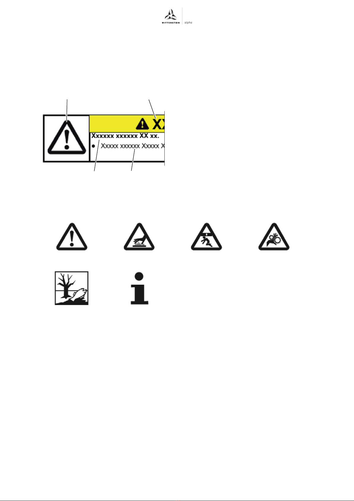
2.6 Structure of warning instructions..........................................................................6
2.6.1 Safety symbols ................................................................................................6
2.6.2 Signal words....................................................................................................7
3 Description of the gearbox..................................................................................8
3.1 Overview of gearbox components .......................................................................8
3.1.1 Version with through-holes..............................................................................8
3.1.2 Version with threaded bores............................................................................8
3.2 Name plate...........................................................................................................9
3.3 Ordering code ......................................................................................................9
3.4 Dimensions and performance data ....................................................................10
3.5 Information about the lubricant ..........................................................................10
3.6 Notes regarding the IP protection class .............................................................10
4 Transport and storage .......................................................................................11
4.1 Packaging ..........................................................................................................11
4.2 Transport............................................................................................................11
4.2.1 Transport of gearboxes up to size 063..........................................................11
4.2.2 Transport of gearboxes size 080 and up.......................................................12
4.3 Storage ..............................................................................................................12
5 Assembly ............................................................................................................13
5.1 Preparations.......................................................................................................13
5.2 Mounting the motor to the gearbox ....................................................................14
5.3 Mounting the gearbox on a machine..................................................................16
5.3.1 Mounting with through-holes .........................................................................16
5.3.2 Mounting with slotted holes ..........................................................................17
5.3.3 Mounting with threaded bores .......................................................................18
5.4 Components mounted to the output side ...........................................................18
5.4.1 Mounting with shrink disk ..............................................................................19
6 Startup and operation ........................................................................................20
7 Maintenance and disposal.................................................................................21
7.1 Maintenance schedule .......................................................................................21
7.2 Maintenance work..............................................................................................21
7.2.1 Visual inspection ...........................................................................................21
7.2.2 Checking the tightening torques....................................................................21
7.3 Startup after maintenance work .........................................................................21
7.4 Disposal .............................................................................................................21

V.. / NV.. / CV..
en-2 2022-D059517 Revision: 05
8 Malfunctions ...................................................................................................... 22
9 Appendix ............................................................................................................ 23
9.1 Specifications for mounting to a motor.............................................................. 23
9.2 Specifications for mounting to a machine.......................................................... 24
9.2.1 Specifications for mounting with threaded holes .......................................... 24
9.2.2 Specifications for mounting with through-holes ............................................ 25
9.3 Specifications for mounting to the output side................................................... 25
9.3.1 Mounting on the keyed hollow shaft ............................................................. 26
9.4 Specifications for startup and operation............................................................ 26
9.4.1 Mounting position.......................................................................................... 27
9.4.2 Continuous operation.................................................................................... 28
9.5 Tightening torques for common thread sizes in general
mechanical engineering .................................................................................... 28

V.. / NV.. / CV.. About this manual
Revision: 05 2022-D059517 en-3
1 About this manual
This operating manual contains necessary information to safely operate the gearbox.
If this manual is supplied with an amendment (e.g. for special applications), then the information in
the amendment is valid. Contradictory specifications in this manual thereby become void.
The operator must ensure that all persons assigned to install, operate, or maintain the gearbox have
read and understood these instructions in full.
Store these instructions within reach of the gearbox.
Inform colleagues who work in the area around the machine about the safety and warning notices
to avoid injuries.
The original instructions were prepared in German; all other language versions are translations of
these instructions.
1.1 Information symbols and cross references
The following information symbols are used:
Indicates an action to be performed
Indicates the results of an action
Provides additional information about the action
A cross reference refers to the chapter number and the header of the target section
(e. g. 2.3 "Intended use").
A cross reference on a table refers to the table number (e. g. Table "Tbl-15").
1.2 Scope of delivery
Check the completeness of the delivery against the delivery note.
Missing parts or damage must be notified immediately in writing to the carrier, the
insurance company, or WITTENSTEIN alpha GmbH.

Safety V.. / NV.. / CV..
en-4 2022-D059517 Revision: 05
2 Safety
These instructions, especially the safety and warning notices and the rules and regulations valid for
the operating site, must be observed by all persons working with the gearbox.
The following, especially, must be strictly adhered to:
Observe the instructions for transport and storage.
Use the gearbox only in accordance with its intended use.
Carry out maintenance and repair work appropriately and professionally in conformity with the
specified intervals.
Always mount, dismantle, and operate the gearbox properly (e.g. even test run only with
secure mounting).
The manufacturer of the higher-level machine shall, in accordance with its risk assessment,
install protective devices and equipment as appropriate to protect the user from the residual
hazards of the gearbox. Only operate the gearbox with intact and active protective devices
and equipment.
Only operate the gearbox with the correct lubricant (type and amount).
Prevent the gearbox from becoming extremely soiled.
Only carry out modifications or reconstructions when these are approved in writing by the
WITTENSTEIN alpha GmbH.
Personal injuries or material damage, or other claims arising from non-observance of these
minimum requirements, are the sole responsibility of the operator.
In addition to the safety-related information in this manual, also observe any legal and otherwise
applicable rules and regulations, particularly for accident prevention (e.g. personal safety
equipment) and environmental protection.
2.1 EC/EU Directive
2.1.1 Machinery Directive
The gearbox is considered a "machine component" and is therefore not subject to the EC
Machinery Directive 2006/42/EC.
Startup is prohibited within the scope of the EC directive until it has been determined that the
machine in which this gearbox is installed corresponds to the regulations within this directive.
2.2 Personnel
Only technicians who have read and understood this operating manual may perform work on the
gearbox. Based on their training and experience, technicians must be able to evaluate the tasks
assigned to them, in order to recognize and avoid risks.
2.3 Intended use
The gearbox serves to convert torques and speeds. It is suitable for all industrial applications.
The gearbox may not be operated in areas with potentially explosive atmosphere.
In food processing / pharmaceutical / cosmetics, the gearbox may only be used next to or under the
product area. Product-specific deviation regarding the positioning and mounting position are
described in Chapter 3 "Description of the gearbox".
The gearbox has been constructed according to current technological standards and accepted
safety regulations.
To avoid danger to the operator or damage to the machine, apply the gearbox only for its
intended use and in a technically flawless and safe state.
If you notice any altered operating behavior, check the gearbox in accordance with Chapter 8
"Malfunctions".
Read the general safety instructions before beginning to work (see Chapter 2.5 "General
safety instructions").

V.. / NV.. / CV.. Safety
Revision: 05 2022-D059517 en-5
The gearbox is intended for installation on motors that:
- correspond to the design B5 (in the event of deviations, consult our Customer Service
department [Technical Customer Service department]).
- have a radial and axial runout tolerance according to DIN EN 50347.
- have a cylindrical shaft end with tolerance class h6 to k6.
For motor shaft diameter 55 mm and up, m6 is also permissible.
Screw connections between gearbox and attached component such as motors have to be
calculated, dimensioned, mounted, and tested according to current technological standards. Use
the VDI directives VDI 2862 sheet 2 and VDI 2230 for example.
The tightening torques recommended by us can be found in Chapter 9 "Appendix".
Deviating from the recommendations in Chapter 5 "Assembly", washers may be used if the material
of the screw surface features a too low interface pressure.
The hardness of the washer needs to match the property class of the screw.
Take into account the washer for the screw calculation (joint, additional compression set,
surface pressure under screw head and under washer).
2.4 Reasonably foreseeable misuse
Any use is prohibited if
- it contradicts the requirements of chapter 2.3 "Intended use",
- it exceeds the permissible technical data, e.g. speed, force and torque load, temperature,
service life (see also chapter 3.4 "Dimensions and performance data").
2.5 General safety instructions
The operation of the gearbox involves residual risks even when adhering to the intended use.
Rotating components can cause serious injuries:
Before startup, remove objects, loose components (e.g. feather keys), and tools from the
gearbox, in order to avoid danger from thrown parts.
Keep a sufficient distance to moving machine components when the gearbox is running.
Secure the higher-level machine against restarting and unintentional movements during
assembly and maintenance work (e.g. uncontrolled lowering of lifting axes).
A hot gearbox can cause serious burns:
Touch the hot gearbox only with protective gloves.
The noise emissions can cause hearing damage. The continuous noise pressure level may vary
according to product type and gearbox size:
Information about your gearbox is available in the customized performance data (X093–D...),
in the catalog under www.wittenstein-alpha.de, or from our Customer Service / Sales
department.
For noise protection measures, observe the total noise pressure level of the machine.
Loose or overloaded screw connections can cause damage to the gearbox:
Use a calibrated torque wrench to tighten and check all screw connections for which
tightening torques have been specified.
Solvents and lubricants are flammable, can cause skin irritation, and can pollute soil and water:
In case of fire: Do not use a jet of water to extinguish.
Suitable extinguishing agents are powder, foam, water mist and carbon dioxide. Observe
the safety instructions of the lubricant manufacturer (see Chapter 3.5 "Information about
the lubricant").
Use protective gloves to avoid direct skin contact with solvents and lubricants.
Use and dispose of cleaning solvents and lubricants properly.

Safety V.. / NV.. / CV..
en-6 2022-D059517 Revision: 05
A damaged gearbox can cause accidents and injury:
Immediately shut down a gearbox that has been overloaded due to misuse or a machine
crash (see Chapter 2.4 "Reasonably foreseeable misuse").
Replace the damaged gearbox, even if no external damage is visible.
2.6 Structure of warning instructions
2.6.1 Safety symbols
The following safety symbols are used to indicate possible hazards, prohibitions, and important
information:
Warning instructions are situation-specific. They
will be precisely where tasks are described in
which dangers can arise.
The warning instructions in this manual are
designed according to the following pattern:
A = Safety symbol (see Chapter 2.6.1 "Safety
symbols")
B = Signal word (see Chapter 2.6.2 "Signal words")
C = type and consequence of danger
D = avoiding danger
General hazard Hot surface Suspended loads Entanglement
Environmental
protection
Information
AB
CD

V.. / NV.. / CV.. Safety
Revision: 05 2022-D059517 en-7
2.6.2 Signal words
The following signal words are used to indicate possible hazards, prohibitions, and important
information:
This signal word indicates an imminent danger that will cause serious
injuries or even death.
This signal word indicates a potential hazard that could cause serious
injuries and even death.
This signal word indicates a potential hazard that could cause minor
or serious injuries.
This signal word indicates a potential hazard that could lead to
material damage.
A note without a signal word indicates application hints or especially
important information for handling the gearbox.

Description of the gearbox V.. / NV.. / CV..
en-8 2022-D059517 Revision: 05
3 Description of the gearbox
The gearbox is a single- or multi-stage low-backlash servo worm gearbox.
The gearbox must only be operated in mounting position as specified in the order.
Various types of motors can be accommodated using an adapter plate and, where necessary, a
bushing.
The gearbox is equipped with an integrated linear length compensation to compensate for the
expansion of the motor shaft when heated up.
3.1 Overview of gearbox components
3.1.1 Version with through-holes
3.1.2 Version with threaded bores
Gearbox components
E Gear housing
Q Output shaft / Output flange
Q5For an indexing pin for mechanically zeroing the
gearbox/the application.
B Adapter plate
Tbl-1: Overview of gearbox components VT+ / VS+ / NVH / CVS
Gearbox components
M Through-holes
(see Chapter 5.3.1 "Mounting with through-holes")
Tbl-2: Version with through-holes
Gearbox components
E3Housing surface (Gear housing)
M Threaded holes
(see Chapter 5.3.3 "Mounting with threaded bores")
Tbl-3: Version with threaded bores
VT+VS+
NVH CVS
B
Q
Q5
EQ
B
Q
E
B
B
M
M
M
M
E
3
E
3
M

V.. / NV.. / CV.. Description of the gearbox
Revision: 05 2022-D059517 en-9
3.2 Name plate
The identification plate is attached to the gear housing or the input flange.
3.3 Ordering code
* For further information on the mounting position, please refer to Chapter 9.4.1 "Mounting position".
More information is available in our catalog or at www.wittenstein-alpha.de.
Gearbox components VT+ / VS+
M Threaded holes
(see Chapter 5.3.3 "Mounting with threaded bores")
Tbl-4: Version with threaded bores
Designation
A Ordering code
(see Chapter 3.3 "Ordering code")
BRatioi
C Customer material number (optional)
D Serial number
E Lubricant
F Production date
G Data matrix code (optional)
Tbl-5: Identification plate (sample values)
M
M
A B
C
G D E F G
WITTENSTEIN alpha GmbH-Walter-Wittenstein-Str.1-97999 Igersheim
xxxxxxx xxx
Mat. No.: 23456789
SN: 1234567
Lubrication: xxx
i= xx
DMF: 10/18
Made in Germany
Product type
Characteristic
Gearbox variant
Gearbox model
Number of stages
Ratio
Output shape
Number of shrink discs
Mounting position *
Motor connection
Generation
Backlash
Clamping hub diameter
xxxxxxx x - x x x - xxxxx - x x x - x x xx x

Description of the gearbox V.. / NV.. / CV..
en-10 2022-D059517 Revision: 05
3.4 Dimensions and performance data
The dimensions, the maximum permissible speeds and torques, and information on the service life
can be found
- in our catalog,
- at www.wittenstein-alpha.de,
- in the specification software cymex®,
- in the respective customized performance data (X093–D...).
Consult our Customer Service department if the gearbox is older than a year. The user will then
receive the valid performance data.
3.5 Information about the lubricant
3.6 Notes regarding the IP protection class
All gearboxes are permanently lubricated by the manufacturer with
synthetic gear oil (polyglycols) or with a high-performance grease (see
identification plate). All bearings are lubricated for life at the factory.
The products comply with the protection class according to the
catalog in accordance with EN 60529. Except for special versions, they
are not corrosion-protected and must be operated in a clean, dust-free
and dry environment. Moisture penetration in the area of the drive is
inadmissible. In this connection, we recommend additional protection
measures or alternative products.

V.. / NV.. / CV.. Transport and storage
Revision: 05 2022-D059517 en-11
4 Transport and storage
4.1 Packaging
The gearbox is delivered packed in foil and cardboard boxes.
Dispose of the packaging materials at the recycling sites intended for this purpose. Observe
the applicable national regulations concerning disposal.
4.2 Transport
The table "Tbl-6" specifies the maximum gearbox weights. Depending on the version, the actual
weight can be considerably less.
4.2.1 Transport of gearboxes up to size 063
No special method is specified for transporting the gearbox.
Suspended loads can fall and can cause serious injuries and even
death.
Do not stand under suspended loads.
Secure the gearbox before transport with suitable fasteners (e.g. belts).
Impacts, for instance from falling or hard dropping, may damage the
gearbox.
Only use hoisting equipment and lifting accessories with sufficient
capacity.
Never exceed the maximum permissible load for hoisting equipment.
Lower the gearbox slowly.
Applies only to gearboxes VT+:
The hollow shaft is not suitable for the transmission of force.
Deformations or leakages can occur.
Only attach the lifting accessories (e.g. loops) to the outer side of the
housing.
Never lift the gearbox by reaching into the openings of the hollow shaft.
Gearbox size V... 040 050 063 080 100
Maximum weight [kg] 5.6 9.7 16.7 35.5 64.6
Gearbox size NV... / CV... 040 050 063 080 100
Maximum weight [kg] 5.6 8.7 13.7 - -
Tbl-6: Maximum weight [kg]

Transport and storage V.. / NV.. / CV..
en-12 2022-D059517 Revision: 05
4.2.2 Transport of gearboxes size 080 and up
4.3 Storage
Store the gearbox in horizontal position and dry surroundings at a temperature of 0 °C to +40 °C in
the original packaging. Store the gearbox for a maximum of 2 years. Consult our Customer Service
department if the conditions are different.
For storage logistics, we recommend the "first in - first out" method.
For gearboxes size 080 and up, we recommend
the use of hoisting equipment.
You can screw in eye bolts (e.g. acc. to DIN 580)
into the threaded bores [M] in the housing. The eye
bolts (at least 2) are used for attaching the gearbox
securely to the hoisting equipment.
For specifications on the threaded bores, refer
to Chapter 9.2 "Specifications for mounting to a
machine".
M (12x)

V.. / NV.. / CV.. Assembly
Revision: 05 2022-D059517 en-13
5 Assembly
Read the general safety instructions before beginning to work
(see Chapter 2.5 "General safety instructions").
If you have questions about correct mounting, consult our Customer Service department.
5.1 Preparations
Make sure that motor meets the requirements in Chapter 2.3 "Intended use".
Select the screws for fastening the motor to the adapter plate according to the motor
manufacturer's specifications. Observe the minimum screw-in depth in relation to the property
class (see Table "Tbl-7").
Clean/degrease and dry the following components using a clean and lint-free cloth, and a
grease-dissolving, non-aggressive cleaning agent:
- All fitting surfaces to neighboring components
- Centering
- Motor shaft
- Inner diameter of clamping hub
- Bushing, inside and out
Dry all fitting surfaces to neighboring components in order to achieve the proper friction values
of the screw connections.
In addition, check the fitting surfaces for damage and impurities.
Pressurized air can damage the gearbox seals.
Do not use pressurized air to clean the gearbox.
Directly sprayed cleaning agents can alter the frictional values of the
clamping hub.
Only spray cleaning agents onto a cloth for wiping off the clamping hub.
Operation without an adapter plate might lead to damage.
Only install your own adapter plate or replace an adapter plate according
to the specifications of WITTENSTEIN alpha GmbH. Our Customer
Service department will provide you with disassembly instructions for this
purpose.
Operation without an adapter plate is prohibited.
In rare cases, a grease lubricated gearbox may show a small leak at
the input (sweating).
To prevent seeping, we recommend to seal the surfaces between
- adapter plate and drive housing (gearbox), as well as between
- adapter plate and motor,
using a surface sealing adhesive (e.g. Loctite® 573 or 574).
Property class of screws for fastening the motor 8.8 10.9 Ax-70 Ax-80
Minimum screw-in depth 1.5 x d 1.8 x d 1.5 x d (*)
d = Screw diameter
(*) Only use a tool that is suitable for working with stainless steel.
Tbl-7: Minimum screw-in depth of screws for fastening the motor to the adapter plate

Assembly V.. / NV.. / CV..
en-14 2022-D059517 Revision: 05
5.2 Mounting the motor to the gearbox
Only the “self-contained version” gearbox
variant with a drive shaft [O] is not intended for
motor mounting. It is possible to drive the
gearbox directly via the drive shaft, e.g. by
means of a belt pulley.
For all gearboxes with motor-mounting, the
following information applies:
Observe the specifications and safety instructions of the motor
manufacturer.
Observe the safety and processing instructions for the threadlocker to be
used.
Valid only for corrosion resistant gearboxes and gearboxes in
Hygienic Design:
Align the geometry of the seal surfaces before mounting the motor.
For corrosion resistant gearboxes, use sealing adhesives
(e. g. Loctite®573) to avoid leaks.
Place an appropriate sealing ring between adapter plate and motor for
gearboxes in Hygienic Design to avoid leaks.
In addition, WITTENSTEIN alpha GmbH offers a suitable sealing plate.
The tightening torque value [TA] of the clamping bolt
[H] can be found on the clamping hub [C].
The value for the tightening torque can also be
found in Chapter 9.1 "Specifications for mounting
to a motor".
O
XX Nm
H
C
TA
C

V.. / NV.. / CV.. Assembly
Revision: 05 2022-D059517 en-15
If the clamping bolt [H1] is loosened too far or removed, the clamping ring [I] can rotate on the
clamping hub. Align it so that the clamping bolt [H1] is in the keyway of the clamping hub
(see table "Tbl-8").
For certain motor shaft diameters and applications, a slotted bushing needs to be installed in
addition.
For the version with clamping bolt, eccentrical [H1]:
The slot of the bushing (if present) and the clamping hub must be flush with the groove
(if present) of the motor shaft; see Table "Tbl-8".
For the version with clamping bolt, centrical [H2]:
The slots of the bushing (if present) and clamping hub have to be aligned with the keyway
(if present) of the motor shaft and rotated 90° from the clamping bolt, see Table "Tbl-8".
No gap is permitted between the motor [D] and the adapter plate [B].
Apply threadlocker (e. g. Loctite®243) to the four screws [F].
Fasten the motor [D] onto the adapter plate [B] with the four screws. Evenly tighten the screws
crosswise with increasing torque.
Tighten the clamping bolt [H] of the clamping hub [C].
The value for the tightening torque can also be found in Chapter 9.1 "Specifications for
mounting to a motor".
For the version with a stopper plug [A], push the plug into the adapter plate [B] all the way to
the stop.
Preferably, the motor should be mounted in a vertical
orientation.
Remove the locking screw / stopper plug [A] from the
mounting bore in the adapter plate [B].
Rotate the clamping hub [C] until the clamping bolt [H] can
be reached via the mounting bore.
Loosen the clamping bolt [H] of the clamping hub [C] by one
revolution.
Slide the motor shaft into the clamping hub of the
gearbox [E].
The motor shaft should slide in easily. If this is not the case,
the clamping bolt needs to be loosened some more.
Designation
H1Clamping bolt, eccentrical
H2Clamping bolt, centrical
I Clamping ring
J Bushing
K Keyed motor shaft
L Motor shaft with shaft key
L1Shaft key
Tbl-8: Arrangement of motor shaft, clamping bolt and bushing
A
B
H
C
D
E
F
TA
H
1
JK
H
2
L
KL
1
I
I

Assembly V.. / NV.. / CV..
en-16 2022-D059517 Revision: 05
For the version with a locking screw [A], turn the screw into the adapter plate [B].
For screw size and specified tightening torque, see Table "Tbl-9".
5.3 Mounting the gearbox on a machine
Center the gearbox in the machine bed.
Apply threadlocker (e. g. Loctite®243) to the fastening screws.
Mount the gearbox so that the identification plate can still be read.
The specified screw sizes and tightening torques can be found in Chapter 9.2 "Specifications
for mounting to a machine".
If your gearbox is equipped with a liquid-cooled adapter plate, the separate manual "Cooled
adapter plate" (doc. no. 2022–D063351) applies for this. The manual will be provided by our
Sales / Customer Service department on request. Please always provide the serial number.
WITTENSTEIN alpha GmbH offers corresponding mounting kits for gearboxes in Hygienic
Design. The separate instructions "Hygienic Design Instruction Sheet, Mounting Kit" (Doc. no.
2022–D062618) are valid for this. The manual will be provided by our Sales / Customer Service
department on request. Please always provide the serial number.
5.3.1 Mounting with through-holes
Width across flats [mm] 5 8 10 12
Tightening torque [Nm] 10 35 50 70
Tbl-9: Tightening torques for the locking screw
Observe the safety and processing instructions for the threadlocker to be
used.
If your gearbox is equipped with reverse centering for motor-
side installation [M] on a machine, you will find more
information in the separate manual "Reverse centering device
for motor-side installation" (doc. no. 2022–D063062). The
manual will be provided by our Sales / Customer Service
department on request. Please always provide the serial
number.
We recommend doing without washers as long as the
material of the screw surface features sufficient interface
pressure.
Fasten the gearbox on the machine with the fastening screws
through the through-holes [M].
M
M
M
M

V.. / NV.. / CV.. Assembly
Revision: 05 2022-D059517 en-17
5.3.2 Mounting with slotted holes
Use only the washers included with the delivery for fastening the gearbox to the machine (see
Chapter 9.2 "Specifications for mounting to a machine").
Pinning the mounted and aligned gearbox (optional)
The gearbox can be optionally equipped with an output
pinion [P1]. The gearing backlash between output pinion and
toothed rack/counter-wheel can be adjusted using the slotted
holes [M] and the lateral guides. An additional adjustment
mechanism is no longer necessary.
Detailed information on the design of the gearbox interface is
available on request.
For the proper setting of the gearing backlash, you will find
further information in the "alpha rack and pinion system"
manual (doc. no. 2022–D001333). The manual will be provided
by our Sales / Customer Service department on request.
Please always provide the serial number.
Operating the gearbox without a motor (e.g. using a hand wheel) is
permitted for setting / aligning the output pinion on the toothed rack.
When doing so, ensure never to tilt / bend the clamping hub.
Slide the washers onto the fastening screws.
Fasten the gearbox to the machine with the
fastening screws through the slotted holes [M].
Optionally, there are two bore holes [N] on the gear housing for pinning
the gearbox to the machine. You can fasten the gearbox to the machine
with cylinder pins.
Drill pin holes into the machine bed according to the bores [N] of the
gear housing.
Ream the bores to the corresponding fit size for the cylinder pins.
For specifications on the cylinder pins, refer to Chapter 9.2
"Specifications for mounting to a machine".
Fasten the gearbox with the cylinder pins.
P
1
MM
M
N

Assembly V.. / NV.. / CV..
en-18 2022-D059517 Revision: 05
5.3.3 Mounting with threaded bores
5.4 Components mounted to the output side
The output side has different shapes depending on the product type:
- Smooth shaft
- Shaft with key
- Splined shaft (DIN 5480)
- Slip-on shaft / hollow shaft / hollow shaft interface / flange hollow shaft
- Flange
- with mounted output pinion
For details on how to mount the slip-on shaft / hollow shaft / hollow shaft interface, refer to
the instructions in Chapter 5.4.1 "Mounting with shrink disk".
For details on how to fasten the flange / flange hollow shaft / keyed hollow shaft, refer to
the instructions in Chapter 9.3 "Specifications for mounting to the output side".
WITTENSTEIN alpha GmbH offers corresponding mounting kits for gearboxes in Hygienic
Design. The separate instructions "Hygienic Design Instruction Sheet, Mounting Kit" (Doc. no.
2022–D062618) are valid for this. The manual will be provided by our Sales / Customer Service
department on request. Please always provide the serial number.
We recommend doing without washers as long as the
material of the screw surface features sufficient interface
pressure.
Fasten the gearbox to the machine with the fastening screws
through the threaded bores [M].
Tension during assembly may damage the gearbox.
Mount the mounting parts onto the output shaft / output flange without
using force.
Never attempt to assemble by force or hammering!
Only use suitable tools and devices for assembly.
Make sure not to exceed the maximum permissible static axial forces on
the output bearing (see Chapter 9.3 "Specifications for mounting to the
output side") when pulling or shrink-fitting a mounting part onto the output
side.
M
This manual suits for next models
6
Table of contents
Other Wittenstein Alpha Engine manuals
Popular Engine manuals by other brands

MTU
MTU 20V4000L33F operating instructions

Siemens
Siemens 1PA6 Series instructions

Paccar
Paccar PX-9 Operator's manual

Briggs & Stratton
Briggs & Stratton 400000 Professional Series quick start guide

RADEMACHER
RADEMACHER RolloTube S-line DuoFern Brief instructions for installation and initial commissioning

DLE
DLE DLE35RA user manual