Wittenstein cyber motor M Series User manual

AC: 50015493 5022-D039778 Revision: 06
Mxxx / Axxx
Rotating / linear electrical machine
Operating Manual

Mxxx / Axxx
5022-D039778 Revision: 06
© WITTENSTEIN cyber motor GmbH 2019
Diese Dokumentation ist urheberrechtlich geschützt.
Alle Rechte, auch die der fotomechanischen Wiedergabe, der Vervielfältigung und der
Verbreitung mittels besonderer Verfahren (zum Beispiel Datenverarbeitung,
Datenträger und Datennetze), auch teilweise, behält sich die
WITTENSTEIN cyber motor GmbH vor.
Inhaltliche und technische Änderungen vorbehalten.
This documentation is copyright protected.
WITTENSTEIN cyber motor GmbH reserves all rights to photo-mechanical
reproduction, copying, and the distribution by special processes (such as computers, file
media, data networks), in whole or in part.
Subject to technical and content changes without notice.
Questa documentazione è protetta dai diritti d'autore.
WITTENSTEIN cyber motor GmbH si riserva tutti i diritti, anche quelli relativi alla
riproduzione fotomeccanica, alla riproduzione e alla diffusione, anche parziali, eseguite
secondo processi particolari (quali ad es. l'elaborazione di dati, il supporto dati e le reti
di dati).
Con riserva di modifiche tecniche e di contenuto.
Cette documentation est protégée par copyright.
Tous les droits de reproduction même partielle, de diffusion et de transmission
photomécanique ainsi que par des procédés techniques spéciaux. (tels le traitement de
données, les supports et réseaux de données) sont réservés à
WITTENSTEIN cyber motor GmbH.
Sous réserve de modifications techniques et de fond.
Este documento es propiedad registrada.
WITTENSTEIN cyber motor GmbH se reserva todos los derechos de reproducción
fotomecánica, copia y divulgación, también en forma de extractos y por procedimientos
especiales (como editores de datos, memorias de datos y redes de datos).
Sujeto a modificaciones técnicas y de contenido sin previo aviso.
本ドキュメントは著作権で保護されています。
写真製版の複製、特別な手続き(データ処理、データキャリア、データネットワー
ク等)を介した複製と配布(抜粋を含む)に関する全ての権利は
WITTENSTEIN cyber motor GmbH に帰属します。
本取扱説明書の記載内容、及び技術的内容は予告なく変更されることがあります。

Mxxx / Axxx
Revision: 06 5022-D039778 en-1
日本語 español français italiano english deutsch
Operating Manual - english
Service
In case you have technical questions, please contact:
WITTENSTEIN cyber motor GmbH
Sales
Walter-Wittenstein-Straße 1
D-97999 Igersheim
In the event of technical malfunctions,
please contact us under the following address:
WITTENSTEIN cyber motor GmbH
Customer Service
Walter-Wittenstein-Straße 1
D-97999 Igersheim
This operating manual may be obtained from WITTENSTEIN cyber motor GmbH by
specifying article number 50015493. Alternatively, it is available to download at:
http://wittenstein-cyber-motor.de
Tel.: +49 7931 493-15800
Fax: +49 7931 493-10905
E-mail: [email protected]
Tel.: +49 7931 493-15900
Fax: +49 7931 493-10903
E-mail: [email protected]

Mxxx / Axxx
en-2 5022-D039778 Revision: 06
deutsch english italiano français español 日本語
Contents
1 About this manual ................................................................................................4
1.1 Signal words ........................................................................................................4
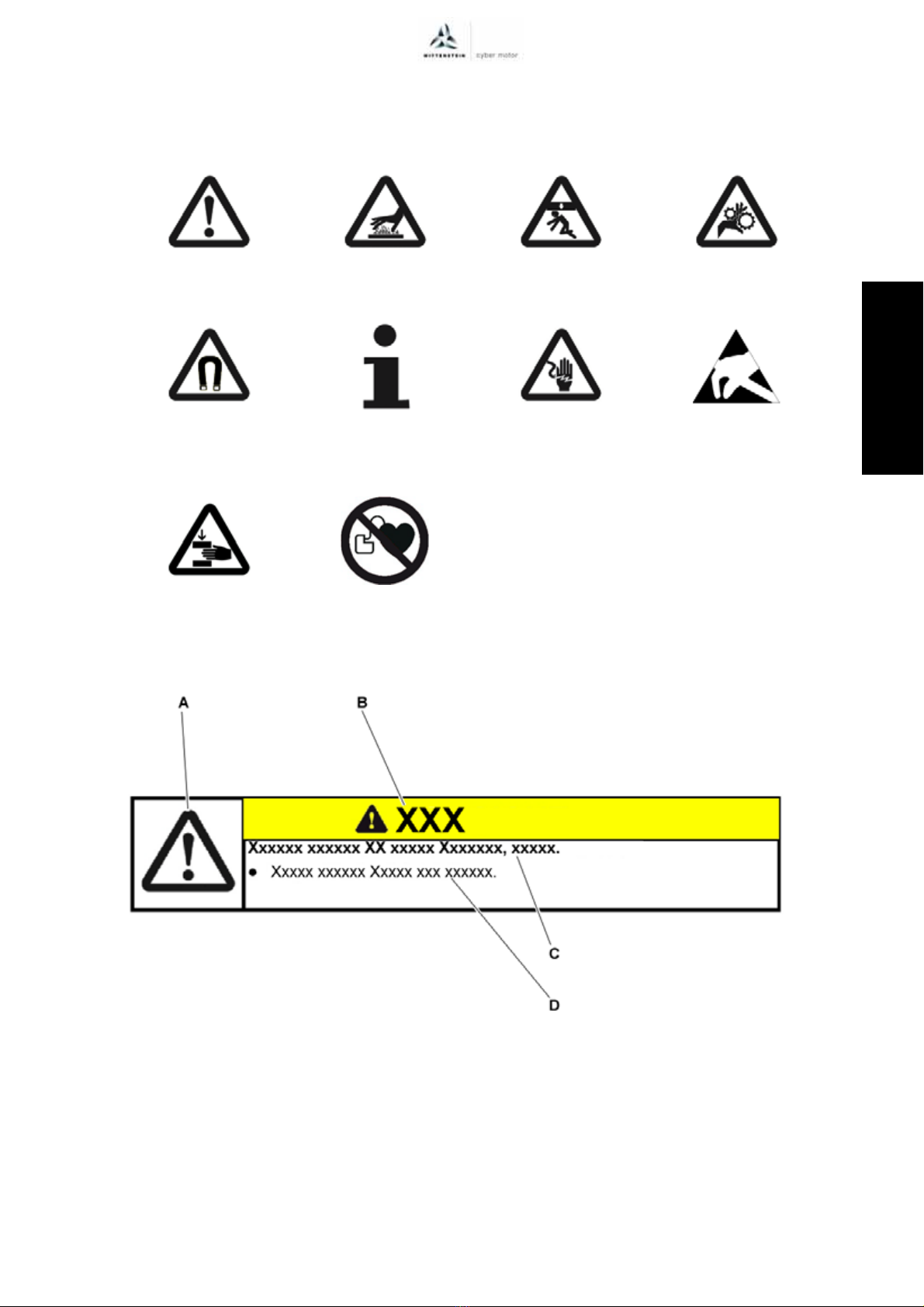
1.2 Safety symbols.....................................................................................................5
1.3 Design of the safety instructions ..........................................................................5
1.4 Information symbols.............................................................................................5
2 Safety.....................................................................................................................6
2.1 EC/EU Directive ...................................................................................................6
2.2 Dangers ...............................................................................................................6
2.3 Personnel.............................................................................................................6
2.4 Intended use ........................................................................................................6
2.4.1 Cooling type H and version H..........................................................................6
2.4.2 Version R.........................................................................................................6
2.4.3 Version V.........................................................................................................7
2.4.4 Version L .........................................................................................................7
2.5 Guarantee and liability .........................................................................................7
2.6 Other applicable documents ...............................................................................7
2.7 General safety instructions ..................................................................................7
3 Description of the motor....................................................................................11
3.1 General information ...........................................................................................11
3.2 Name plate.........................................................................................................11
3.2.1 MRxx series name plate................................................................................12
3.2.2 Name plate for ARxx series (motor-gearbox combination) ...........................13
3.2.3 ALxx series name plate (linear actuator).......................................................14
3.2.4 MLxx / PLxx / SLxx series nameplate (linear motor) .....................................15
3.3 Performance data ..............................................................................................15
3.4 Temperature monitoring.....................................................................................15
3.5 Weight................................................................................................................15
4 Transport and storage .......................................................................................16
4.1 Scope of delivery ...............................................................................................16
4.2 Packaging ..........................................................................................................16
4.3 Transport............................................................................................................16
4.4 Storage ..............................................................................................................16
5 Assembly ............................................................................................................17
5.1 Preparations.......................................................................................................17
5.1.1 Preparations for ALxx series (linear actuators) .............................................17
5.2 Attaching Motor to a machine ............................................................................18
5.3 Components mounted to the output side ...........................................................18
5.4 Connecting the cooling circuit ............................................................................19
5.5 Installing electrical connections .........................................................................20
5.6 Installing a kit motor ...........................................................................................21
5.6.1 Installing the stator ........................................................................................22
5.6.2 Installing the rotor..........................................................................................23
5.7 Installing the primary part / secondary part........................................................24
6 Startup and operation ........................................................................................26
6.1 Safety instructions and operating conditions .....................................................26
6.1.1 Humidity / Temperature.................................................................................26
6.1.2 Vibration ........................................................................................................26
6.1.3 Shock ............................................................................................................26
6.1.4 Holding brake ................................................................................................27
6.2 Operation ...........................................................................................................29
6.2.1 Voltage gradient ............................................................................................29
6.2.2 Operation of Mxxx / ARxx..............................................................................29

Mxxx / Axxx
Revision: 06 5022-D039778 en-3
日本語 español français italiano english deutsch
7 Maintenance and disposal.................................................................................30
7.1 Maintenance work..............................................................................................30
7.1.1 Cleaning ........................................................................................................30
7.1.2 Checking the holding brake...........................................................................30
7.1.3 Visual inspection ...........................................................................................30
7.1.4 Relubrication .................................................................................................30
7.1.5 Motor feedback system .................................................................................31
7.2 Start-up after maintenance work........................................................................31
7.3 Disposal .............................................................................................................31
8 Malfunctions .......................................................................................................32
9 Appendix .............................................................................................................33
9.1 Adapted regulations for functional model, development sample or A sample ...33
9.1.1 Intended use..................................................................................................33
9.1.2 Guarantee and liability...................................................................................33
9.2 Tightening torques for common thread sizes in general
mechanical engineering .....................................................................................33

About this manual Mxxx / Axxx
en-4 5022-D039778 Revision: 06
1.1 Signal words
deutsch english italiano français español 日本語
1 About this manual
This manual contains necessary information for the safe use of the electro-mechanical actuator
Mxxx or Axxx. The electromagnetic actuator (including motors, motor-gearbox combinations and
linear actuators) will be referred to simply as the motor in the following.
Every motor is identified uniquely with its material number (MN, actual term) respectively article
code (AC, former term) and serial number (SN) (also see chapter 3.2 "Name plate").
In case of conflict between this general operating manual and the product-specific documentation,
the product-specific documentation applies. This operating manual is valid for the product (motor)
unless another, product-specific documentation exists.
If the product was delivered as a functional model, development sample or A sample, this status is
clearly indicated in the order confirmation and the delivery note. In this case, adapted regulations
regarding the intended use (see chapter 2.4 "Intended use") as well as the guarantee and liability
(see chapter 2.5 "Guarantee and liability"), described in the appendix of this document apply.
The operator must ensure that these instructions are read through by all persons assigned to install,
operate, or maintain the motor, and that they fully comprehend them.
Store these instructions within reach of the motor.
These safety instructions should be shared with colleagues working in the vicinity of the device
to ensure individual safety.
The original instructions were prepared in German; all other language versions are translations of
these instructions.
1.1 Signal words
The following signal words are used to indicate possible hazards, prohibitions, and important
information:
This signal word indicates an imminent danger that will cause serious
injuries or even death.
This signal word indicates a potential hazard that could cause serious
injuries and even death.
This signal word indicates a potential hazard that could cause minor
or serious injuries.
This signal word indicates a potential hazard that could lead to
material damage.
A note without signal word draws your attention to application tips or
especially important information when handling the motor.

Mxxx / Axxx About this manual
Revision: 06 5022-D039778 en-5
1.2 Safety symbols
日本語 español français italiano english deutsch
1.2 Safety symbols
The following safety symbols are used to indicate possible hazards, prohibitions, and important
information:
1.3 Design of the safety instructions
The safety instructions of these instructions are designed according to the following pattern:
1.4 Information symbols
The following information symbols are used:
Indicates an action to be performed
Indicates the results of an action
Provides additional information on handling
General danger Hot surface Suspended loads Danger of being pulled
in
Magnetic field Information Electric voltage Electrostatic
discharge sensitive
component
Crushing hazard Pacemaker ban
A = Safety symbol (see Chapter 1.2 "Safety symbols")
B = Signal word (see Chapter 1.1 "Signal words")
C = Type and consequence of the danger
D = Prevention of the danger

Safety Mxxx / Axxx
en-6 5022-D039778 Revision: 06
2.1 EC/EU Directive
deutsch english italiano français español 日本語
2 Safety
This instruction, in particular the safety notes, and the rules and regulations applicable at the usage
site are to be observed by all individuals working with the motor.
In addition to the safety instructions in this manual, also observe any (legal and otherwise)
applicable environmental and accident prevention rules and regulations (e.g. personal safety
equipment).
2.1 EC/EU Directive
The motor has been constructed in accordance with the relevant EC/EU directives for the relevant
model and design. The motor complies with all applicable EC/EU regulations. The motor bears the
CE marking to the extent required by applicable EC/EU regulations.
Observe applicable regulations for electrical installation (e.g. wire cross-sections, fuses).
It is the responsibility of the plant builder to ensure that all requirements that apply to the entire
system are fulfilled.
The EC/EU Declaration of Conformity or Declaration of Incorporation of Incomplete Machinery can
be found in the download area of our website http://wittenstein-cyber-motor.de. Please contact our
sales department if you have any questions. Always provide the serial number when doing so.
The motor and all its individual components are RoHS compliant according to the Directive
2011/65 / EU, unless customer specific requirements make this directive void.
2.2 Dangers
The motor has been built in accordance with the current state of the art and the generally accepted
safety engineering practice.
The motor may be used for its intended purpose (ref. chapter 2.4 "Intended use") and in a flawless
condition with regard to safety only in order to avoid danger to the user or damage to the machine.
Read the general safety instructions before beginning work (see Chapter 2.7 "General safety
instructions").
2.3 Personnel
Only persons who have read and understood these instructions may carry out work on the motor.
2.4 Intended use
The motor is designed for use in industrial systems.
The motor can be optionally equipped with a holding brake.
- A holding brake is no safety brake, as defined by DIN EN 13849-1 or by the German BGHM
regarding hanging axes (only available in German), and is therefore not intended to be used
as a brake for the protection of persons or as a dynamic brake.
Information on the intended use of specific motor versions can be found in the sections below.
2.4.1 Cooling type H and version H
Motors of cooling type H and version H, recognizable by the 30-digit type code (position 13 and
position 25) xxxxxxxx-xxxH-xxxxx-xxxxHx-xxx, may only be operated when completely filled with
oil. Please contact our sales department for information on the permissible oil types. Always provide
the serial number when doing so.
2.4.2 Version R
Motors design R, recognizable by the 30-digit type code (position 25) xxxxxxxx-xxxx-xxxxx-xxxxRx-
xxx, may not be used in applications that are critical for safety. Only gearboxes that have been
applied with grease may be installed in motors of design R. Installing gearboxes that have been
applied with oil is not permitted. Please contact our sales department for information on the
permissible grease types. Always provide the serial number when doing so.

Mxxx / Axxx Safety
Revision: 06 5022-D039778 en-7
2.5 Guarantee and liability
日本語 español français italiano english deutsch
2.4.3 Version V
With motors of version V, recognizable by the 30-digit type code (position 25) xxxxxxxx-xxxx-xxxxx-
xxxxVx-xxx, any contamination of the motor (e.g. through improper handling) must be avoided. This
applies in particular to assembly and operation. If the attachment of a gearbox is permissible, then
only suitable grease-lubricated gearboxes may be attached. Attaching oil-lubricated gearboxes is
not permissible. Please contact our sales department for information on the permissible grease
types. Always provide the serial number when doing so.
2.4.4 Version L
With motors of version L, recognizable by the 30-digit type code (position 25) xxxxxxxx-xxxx-xxxxx-
xxxxLx-xxx, any contamination of the motor (e.g. through improper handling) must be avoided. This
applies in particular to assembly and operation. In case of soiling, clean using a suitable method. If
the attachment of a gearbox is permissible, then only suitable grease-lubricated gearboxes may be
attached. Attaching oil-lubricated gearboxes is not permissible. Please contact our sales
department for information on the permissible grease types. Always provide the serial number when
doing so.
2.5 Guarantee and liability
Guarantee and liability claims are excluded for personal injury and material damage in case of
- Ignoring the information on transport and storage
- Improper use (misuse)
- Improper or neglected maintenance and repair
- Improper assembly / disassembly or improper operation
- Operation of the motor with defective protection devices and mechanisms
- Operation of a severely soiled motor
- Changes or modifications that have been realized without the written approval of
WITTENSTEIN cyber motor GmbH
2.6 Other applicable documents
You have already received the following documents for your specific motor:
- Customer drawing (5007–...)
- Signal list (5085–...)
- Motor speed and torque characteristics (5012–...)
For additional information, please contact our sales department. Always provide the serial number
in this case.
2.7 General safety instructions
Electrical connection work refers to all work on the electrical circuit for which faults and
associated hazards cannot be excluded.
Typically, plugging motor connectors into power electronics sockets in a voltage-free state is
not part of this electrical connection work.
Faulty electrical connections or not approved, current-carrying
components can cause serious injuries and even death.
Have all electrical connection work performed by trained technicians
only. The valid standards and directives must be observed for this.
Only suitable tools may be used for connection work.
Immediately replace damaged cables or plugs.

Safety Mxxx / Axxx
en-8 5022-D039778 Revision: 06
2.7 General safety instructions
deutsch english italiano français español 日本語
When the motor shaft is still turning or when the motor is externally
driven (generator operation), voltage is induced. This can lead to lethal
current pulses.
Ensure that no plugs or connections are exposed.
Connecting the power and signal leads under voltage (e.g. plugging
the motor connectors into the live sockets of the power electronics) is
not permitted and can lead to machine damage, serious injury or even
death.
Make sure that the motor and the motor connections of the electronics
(for power and signal) are always in a voltage-free state before
connecting.
Separation of the power and signal supply lines under voltage is not
permitted and can lead to machine damage, serious injury or even
death.
Make sure that the drive is always in a voltage-free state before
disconnecting its power and signal supply (e.g. disconnecting the motor
connectors).
Components equipped with permanent magnets and components that
feature magnetic fields can influence/impede the function of active
medical implants (e.g. pacemakers, defibrillators). This can lead to
severe injuries or even death.
Keep a sufficient distance to these components (stator, rotor) during
assembly.
If permanent magnets or permanent magnetic fields are directly
accessible (especially with rotary kit motors or the primary and
secondary parts of linear motors), you are prohibited from approaching
these motor parts.
If there are concerns, contact the manufacturer of the active medical
implants or consult WITTENSTEIN cyber motor GmbH.
Objects flung out by moving components can cause serious injuries
and death.
Remove objects and tools from the motor prior to starting it up.

Mxxx / Axxx Safety
Revision: 06 5022-D039778 en-9
2.7 General safety instructions
日本語 español français italiano english deutsch
Moving components on the motor can pull in or crush parts of the
body and cause serious injuries and even death.
Keep a sufficient distance to moving machine components when the
motor is running.
Secure the machine against restarting and unintentional movements
during assembly and maintenance work.
A wrong direction of rotation or direction of movement may result in
serious injury or death.
The direction of rotation or movement may differ from the standard
IEC 60034-8.
Before and during startup, ensure that the motor has the correct direction
of rotation or movement.
Be sure to avoid collision (caused e.g. by crashing against an end stop).
With the danger area secured, check the direction of rotation or
movement in a slow motion, ideally by limiting the current and torque.
A damaged motor can cause accidents with the risk of injury.
Never operate a motor that has been overloaded due to misuse or a
machine crash.
Replace the affected motors, even if no external damage is visible.
A hot motor housing may cause severe burns.
Touch the motor housing with protective gloves or after a longer standstill
of the motor only.
Mechanical assembly of the motor to the application and mechanical
maintenance may result in handling errors leading to serious crush
injuries as well as damage to the motor or the application
Have all mechanical assembly and maintenance work carried out by
trained personnel only.
Only use suitable tools for assembly and maintenance work.

Safety Mxxx / Axxx
en-10 5022-D039778 Revision: 06
2.7 General safety instructions
deutsch english italiano français español 日本語
During the mechanical assembly and maintenance of kit motors
(rotary motors without housings or linearly moving primary and
secondary parts), the attractive forces of the permanent magnets can
cause severe crushing injuries and damage to the motor or the
application.
Have all mechanical assembly and maintenance work carried out by
trained personnel only.
Only use suitable (e.g. non-ferromagnetic) tools for assembly and
maintenance work.

Mxxx / Axxx Description of the motor
Revision: 06 5022-D039778 en-11
3.1 General information
日本語 español français italiano english deutsch
3 Description of the motor
3.1 General information
All motors are brushless electrical machines and conform to the applicable standards and
regulations, in particular:
-IEC 60034 Rotating electrical machines
-2006/95/EC Low-Voltage Directive, if the directive applies to the motor according to article 1
(valid until 19 Apr 2016 [time of production])
-2014/35/EU Low-Voltage Directive, if the directive applies to the motor according to article 1
(valid from 20 Apr 2016 [time of production]: Supersedes the old directive 2006/95/EC)
The motor can be optionally equipped with a holding brake. The holding brake is not a safety brake.
The variants of the motors without housing enable individual installation on the part of the
customer. Generally, this results in especially compact and low-mass drive solutions. The deviating
assembly procedure is described in Chapter 5.6 "Installing a kit motor".
In general, the ALxx series motors (linear actuators) consist of a synchronous servo motor with
integrated threaded spindle and bearings:
- The rotation of the motor is transformed into a linear movement of the tappet via the threaded
spindle. Depending on the required accuracy, power density and efficiency, trapezoidal, ball
screw or planetary roller spindles are used as threaded spindles.
- If it is not possible to realize a rotation lock with the customer's equipment, a linear actuator
with the optional integrated rotation lock must be used.
3.2 Name plate
The name plate contains important information about the motor characteristics.
Customer-specific variations of the design of the name plate are permissible.
Use the motor designation (B) to select the corresponding EC Declaration of Conformity in our
download area (see Chapter 2.1 "EC/EU Directive").
Further details can be found in the supplied motor speed and torque characteristics (5012-...).

Description of the motor Mxxx / Axxx
en-12 5022-D039778 Revision: 06
3.2 Name plate
deutsch english italiano français español 日本語
3.2.1 MRxx series name plate
The name plate is attached to the motor housing, or, for motors without motor housing on the stator,
to the winding overhang for example.
Designation
A Serial number
B Motor designation (ordering code)
C Material number or article code
(order number)
DUL marking
E Protection class
F Time of manufacture
G Place of manufacture
H Country of manufacture
ICE marking
J Bus DC voltage UDC
K Continuous stall current I0
L No-load speed n0
M Continuous stalling torque M0
N Insulation class
O Customer-specific motor designation
P Braking torque / brake voltage
Q Company headquarters
Tbl-1: MRxx name plate
A B C D E F G H I
J K L M N O P Q

Mxxx / Axxx Description of the motor
Revision: 06 5022-D039778 en-13
3.2 Name plate
日本語 español français italiano english deutsch
3.2.2 Name plate for ARxx series (motor-gearbox combination)
The name plate is attached to the motor housing.
Designation
A Serial number
B Motor designation (ordering code)
C Material number or article code
(order number)
DUL marking
E Protection class
F Time of manufacture
G Place of manufacture
H Country of manufacture
ICE marking
J Bus DC voltage UDC
K Continuous stall current I0
L Allowed continuous output speed nmax
M Allowed continuous output torque M0
N Insulation class
ORatio
P Customer-specific motor designation
Q Braking torque / brake voltage
R Company headquarters
Tbl-2: ARxx name plate
A B C D E F G H I
J K L M N O P Q R

Description of the motor Mxxx / Axxx
en-14 5022-D039778 Revision: 06
3.2 Name plate
deutsch english italiano français español 日本語
3.2.3 ALxx series name plate (linear actuator)
The name plate is attached to the linear actuator housing.
Designation
A Serial number
B Motor designation (ordering code)
C Material number or article code
(order number)
DUL marking
E Protection class
F Time of manufacture
G Place of manufacture
H Country of manufacture
ICE marking
J Bus DC voltage UDC
K Continuous stall current I0
L Maximum speed vmax
M Continuous force F0
N Insulation class
OPitch p
P Customer-specific motor designation
Q Braking torque / brake voltage
R Company headquarters
Tbl-3: ALxx name plate
A B C D E F G H I
J K L M N O P Q R

Mxxx / Axxx Description of the motor
Revision: 06 5022-D039778 en-15
3.3 Performance data
日本語 español français italiano english deutsch
3.2.4 MLxx / PLxx / SLxx series nameplate (linear motor)
The name plate is attached to the motor housing. If primary or secondary parts are fitted, it is
attached, for example, on the side of the respective component.
3.3 Performance data
The maximum permissible technical specifications are available in the motor characteristic
(5012–...).
Please contact our sales department for further information. Always indicate the serial number in
that context.
3.4 Temperature monitoring
On motors with integrated temperature sensor, a tripping device or detection circuit that prevents
the permissible temperature limit from being exceeded needs to be connected to the motor drive.
3.5 Weight
The weight of your motor can be found in the supplied motor speed and torque characteristics
(5012-...).
Designation
A Serial number
B Motor designation (ordering code)
C Material number or article code (order
number)
DUL marking
E Protection class
F Time of manufacture
G Place of manufacture
H Country of manufacture
ICE marking
J Bus DC voltage UDC
K Continuous stall current I0
LStroke
MIdling speed v0
N Insulation class
O Continuous force F0
P Customer-specific motor designation
Q Company headquarters
Tbl-4: MLxx / PLxx / SLxx name plate
If the temperature limit is exceeded, the motor will be damaged.
Select a sufficiently dimensioned motor so that the permissible operating
temperature will not be exceeded even under the most demanding
conditions.
A B C D E F G H I
J K L M N O P Q

Transport and storage Mxxx / Axxx
en-16 5022-D039778 Revision: 06
4.1 Scope of delivery
deutsch english italiano français español 日本語
4 Transport and storage
4.1 Scope of delivery
Check the completeness of the delivery against the delivery note.
Missing parts or damage must be notified immediately in writing to the carrier, the
insurance company, or WITTENSTEIN cyber motor GmbH.
4.2 Packaging
Dispose of the packaging materials at the recycling sites intended for this purpose. Observe
the applicable national regulations concerning disposal.
4.3 Transport
Note the weight of the payload and use an appropriate transport device.
Specifications on the weights, refer to Chapter 3.5 "Weight".
Ambient temperatures between -20° C and +50° C are permissible for transport only.
4.4 Storage
Store the motor in a horizontal position at a temperature of 0 C to + 40 C in the original packaging.
The ambient conditions must be dry, dust-free, and low in vibrations (see Chapter 6.1 "Safety
instructions and operating conditions"). Store the motor for a maximum of 2 years.
For storage logistics, we recommend the "first in - first out" method.
Suspended loads can fall and can cause serious injuries and even
death.
Do not stand under suspended loads.
Secure the motor before transport with suitable fasteners (e.g. belts).
Hard shocks caused by harsh handling during transportation (e.g.
falling, hard dropping) can damage the motor.
Only use hoisting equipment and lifting accessories with sufficient
capacity.
Never exceed the maximum permissible load for hoisting equipment.
Slowly put down the motor.

Mxxx / Axxx Assembly
Revision: 06 5022-D039778 en-17
5.1 Preparations
日本語 español français italiano english deutsch
5 Assembly
Read the general safety instructions before beginning work (see Chapter 2.7 "General safety
instructions").
Unless explicitly agreed otherwise for customer-specific motors, perform the assembly
according to the following sections.
5.1 Preparations
Section 5.6 "Installing a kit motor" lists the different assembly sequence for kit motors.
Clean / degrease the output shaft of the motor with a clean and lint-free cloth as well as a
grease-dissolving, non-aggressive cleaning agent.
Dry all fitting surfaces to neighboring components in order to achieve the proper friction values
of the screw connections.
Check the fitting surfaces additionally for damage and impurities.
Use:
- Property class 10.9 bolts for Mxxx series motors.
- Property class 12.9 bolts for Axxx series motors.
Use:
- Washers (hardness class 300 HV) for motors with an aluminum flange. The contact
pressure must not exceed 230 N/mm2.
-No washers for motors with a stainless steel flange.
5.1.1 Preparations for ALxx series (linear actuators)
Pressurized air may damage the seals of the motor.
Do not use pressurized air for cleaning the motor.
If present, the temperature sensors and rotor position encoders,
particularly Hall Effect sensors and encoders, can be damaged by
electrostatic discharge.
Observe the directives concerning ESD protection.
Improper assembly can damage the linear actuator.
Only install the linear actuator on level, no-vibration, rigid structures.
Ensure freedom of motion of the customer application.
Arrange the linear actuator and the application optimally with respect to
one other to avoid lateral forces and thus premature wear of the threaded
spindle.
Avoid lateral forces and bending torques on the screw.
Avoid banging and knocking the screw.

Assembly Mxxx / Axxx
en-18 5022-D039778 Revision: 06
5.2 Attaching Motor to a machine
deutsch english italiano français español 日本語
5.2 Attaching Motor to a machine
Coat the fastening screws with a threadlocker (e.g. Loctite®243).
Fasten the motor to the machine:
- either via the through-holes of the machine
- or via the through-holes of the motor.
If screws are screwed into the motor, observe the maximum permissible lengths of the
screws.
Mount the motor in such a way that the name plate remains legible.
Only use washers for motors that have an aluminum flange.
For specified tightening torques for screws of property class 10.9 and 12.9, see section 9.2
"Tightening torques for common thread sizes in general mechanical engineering",
table "Tbl-14".
5.3 Components mounted to the output side
Moving outside the permissible stroke path, at both the minimum and
maximum position, will damage the threaded spindle.
Limit the stroke of the linear actuator using appropriate measures (e.g.
stops, buffers) for the extended and retracted end position.
These end stops must be dimensioned appropriately and be capable
of absorbing the kinetic energy of the moving parts, which may be
moving at high speeds.
Mechanical assembly of the motor to the application and mechanical
maintenance may result in handling errors leading to serious crush
injuries as well as damage to the motor or the application
Have all mechanical assembly and maintenance work carried out by
trained personnel only.
Only use suitable tools for assembly and maintenance work.
Observe the safety and processing instructions for the threadlocker to be
used.
Mechanical assembly of the motor to the application and mechanical
maintenance may result in handling errors leading to serious crush
injuries as well as damage to the motor or the application
Have all mechanical assembly and maintenance work carried out by
trained personnel only.
Only use suitable tools for assembly and maintenance work.
This manual suits for next models
6
Table of contents
Other Wittenstein cyber motor Engine manuals