Wittern VendNet SCRUBYRAK 3597 User manual

AUG 2017 4225059•B
VendNetTM
165 North 10th Street
Waukee, IOWA 50263-0488
United States of America
MODEL:
3597 - DISPENSER HOST
3598 - DISPENSER SAT
SERVICE
MANUAL

TABLE OF CONTENTS
INTRODUCTION ............................................................................................................................................ 1
SPECIFICATIONS.......................................................................................................................................... 2
DIMENSIONS ............................................................................................................................................ 2
ELECTRICAL ............................................................................................................................................ 2
MACHINE OPERATION............................................................................................................................ 2
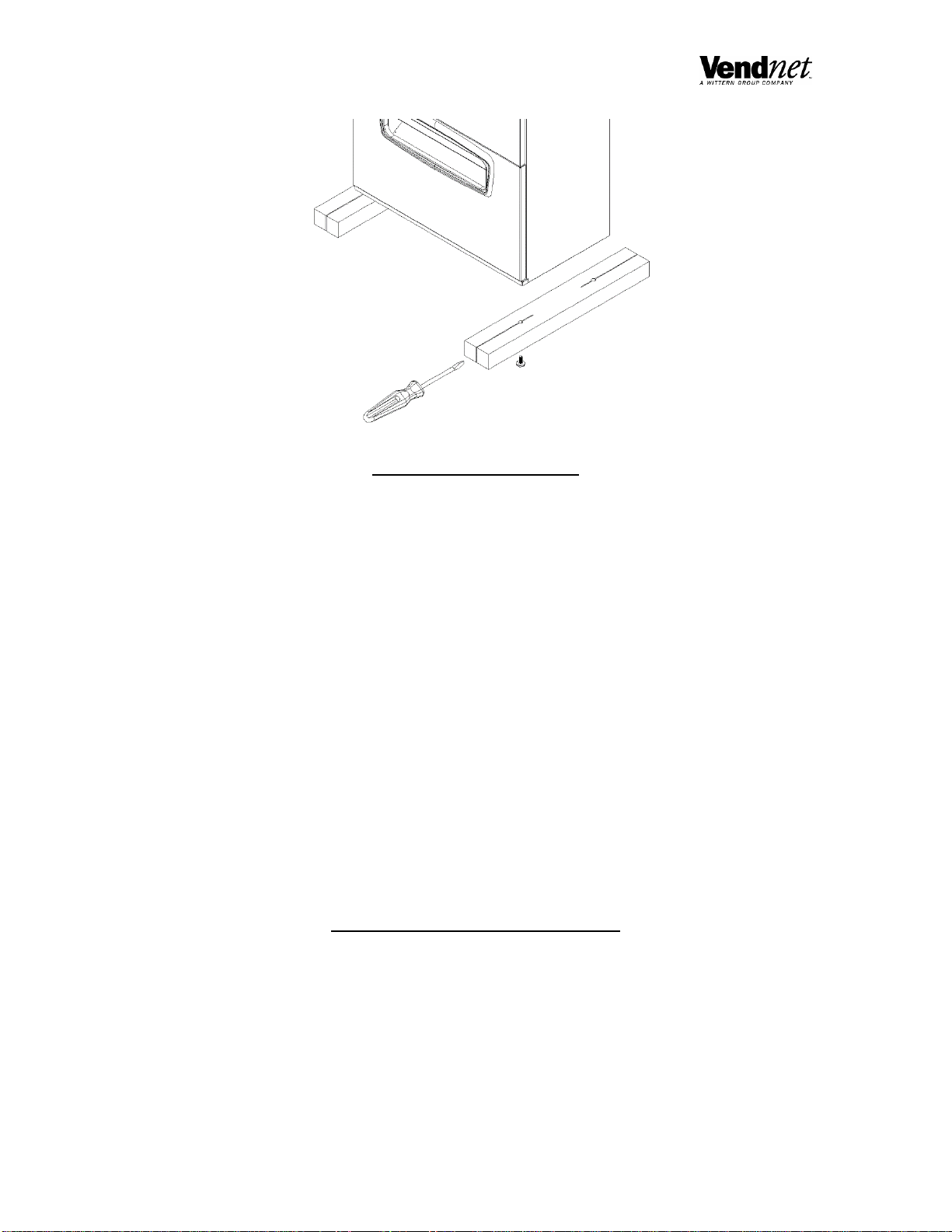
UNPACKING.................................................................................................................................................. 2
INSTALLATION.............................................................................................................................................. 3
GROUNDING (EARTHING) & ELECTRICAL............................................................................................ 3
LOADING PRODUCTS .................................................................................................................................. 3
CONTROLLER FUNCTIONS ......................................................................................................................... 4
DISPENSING MODE ................................................................................................................................. 4
MAKE A SELECTION ............................................................................................................................... 4
DISPENSE CYCLE.................................................................................................................................... 4
COUNTERS............................................................................................................................................... 4
SERVICE MODE........................................................................................................................................ 4
SERVICE MODE BUTTON........................................................................................................................ 4
TOUCH SCREEN ...................................................................................................................................... 4
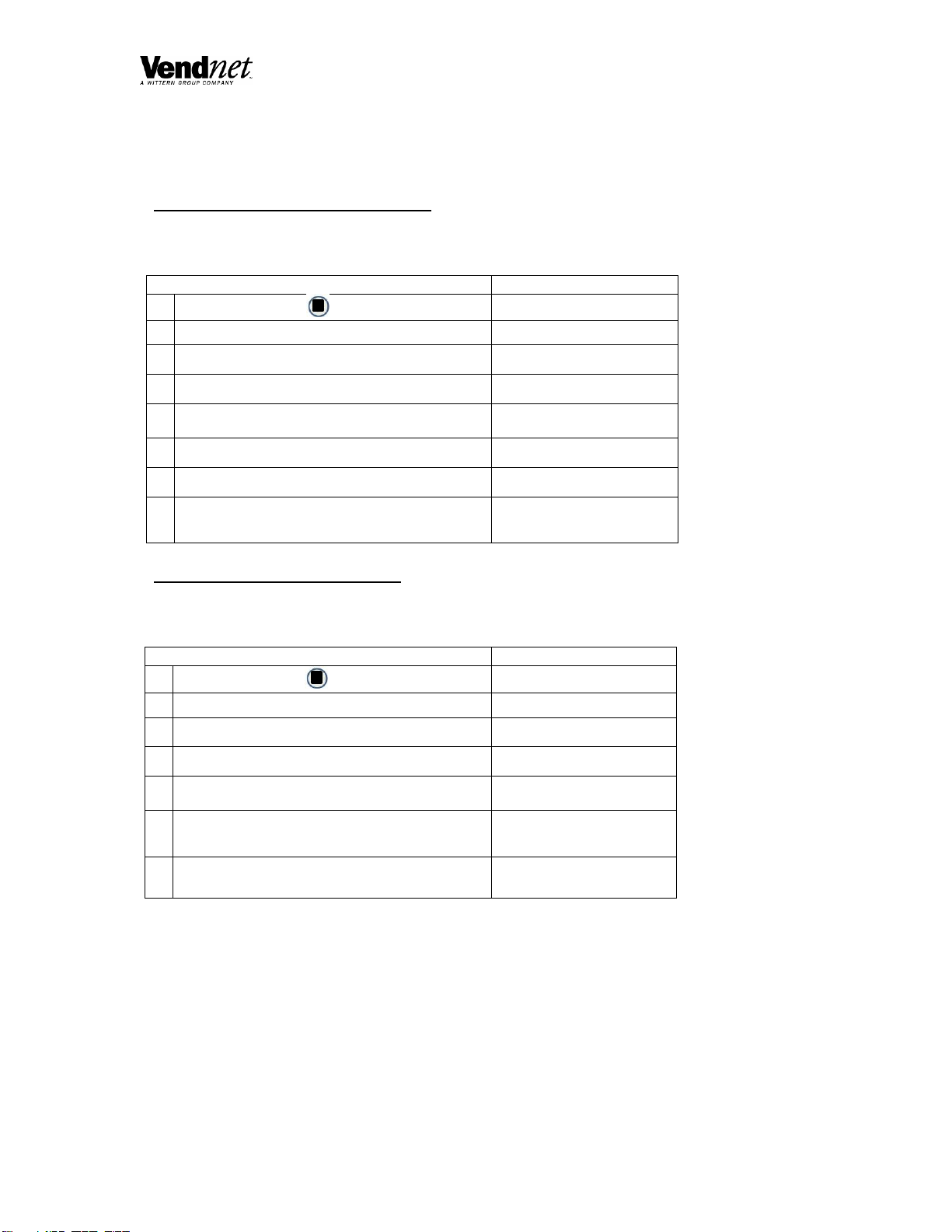
QUICK REFERENCE CHART........................................................................................................................ 5
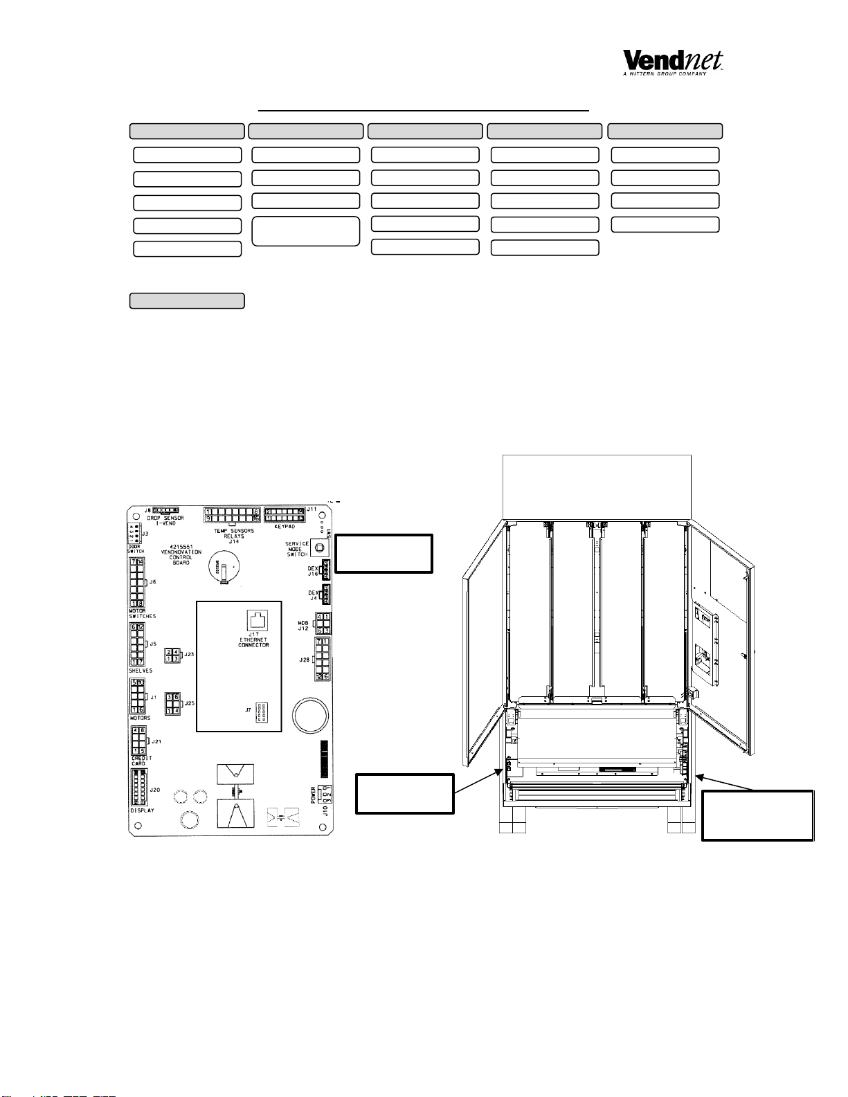
CONTROL BOARD........................................................................................................................................ 5
PREVENTIVE MAINTANENCE.....................................................................................................................10
CLEAN CABINET INTERIOR...................................................................................................................10
CLEAN CABINET EXTERIOR..................................................................................................................10
PARTS ORDERING PROCEDURE...............................................................................................................10
BEFORE CALLING FOR SERVICE..............................................................................................................10
Note:
The Model and Serial numbers are needed for you to obtain quick service and parts information for your
machine. The numbers are given on the identification plate located on the back side of the cabinet of the
machine.
MODEL NUMBER: ___________________________________
SERIAL NUMBER: ___________________________________

4225059•B | SERVICE MANUAL | SCRUB TRAK | DISPENSER | 1
INTRODUCTION
This manual contains instructions, service and installation guidelines for the ScrubTrak product
line.
The Scrub Trak models are equipped with an electronic control system. All dispensing functions
and features are programmed through the controller or online database.
Total dispense cycles performed by the machine, information for individual selections, complete
rows or total machine can be compiled and used for inventory and order records by using the
online database login by going to http://scrubtrak.vendnovation.com and logging in.
Many electrical malfunctions are recorded and displayed by logging in to the database website
and viewing the check book function. Each selection has an individual motor. Functional
selections will continue to operate if other motors become non-functional.
The iVend™ Optical Sensing option assures that the product is received.
Read this manual thoroughly. Become familiar with the
machine’s components and features. The initial setup of
a dispensing machine is a very important step toward
insuring that the equipment operates trouble-free.
Carefully follow the instructions for the initial installation
of the machine to avoid service problems and minimize
setup time.
Access to the service area of this machine should be
permitted only to individuals having knowledge and
practical experience in machine setup and loading,
especially in the areas of safety and security.
If you have questions concerning the
information in the manual, replacement
parts, or the operation of the vendor, note
your machine’s Model #and SN #before
contacting your local distributor or:
VendNet
8040 University Blvd
Des Moines, IA 50325
Phone: (800) 833-4411
Parts Fax: (515) 271-8555
E-mail: vendnet@vendnetusa.com
www.VendNetUSA.com

2| SCRUB TRAK | DISPENSER | SERVICE MANUAL | 4225059•B
SPECIFICATIONS
DIMENSIONS
ELECTRICAL
MACHINE OPERATION
UNPACKING
This machine was thoroughly inspected before leaving the factory and the delivering carrier has
accepted responsibility for this machine. Note any damage or irregularities at the time of delivery
and report them to the carrier. Request a written inspection report from the claims inspector to file
any claim for damage. File the claim with the carrier (not the manufacturer) within 15 days after
receipt of the machine.
Carefully remove the outside packing material being careful not to damage the machine’s finish or
exterior. Inspect the machine for concealed shipping damage. Report any damage hidden by the
shipping material directly to the delivering carrier on a Hidden Damage Report.
Remove the knock-away support by placing a 2X6 under the dispenser. Insert a large screwdriver
or prying tool into the groove and split it in two. Turn the leveling screws as far as possible. See
Figure 1.
Model
3597/3598
(ScrubTrak)
Width
38.5 inches
Weight
588 lbs.
Depth
23 inches
Height
78 inches
Voltage
115 VAC
Cycle
60 Hz
Amperage
1.2
Transformer
115 VAC –24 VAC
Location
Suitable for indoor use only. This appliance is not
suitable for installation in an area where a water jet
could be used.
Sound Level
Produces less than 70 dBA during normal operation.
Recommended
Operating
Temperature
Between 32° and 100° F° (0° and 37.8° Celsius.
NOTE: if the power supply cord is damaged, it
must be replaced by the manufacturer, its
service agent, or similarly qualified individual
in order to avoid hazard.

4225059•B | SERVICE MANUAL | SCRUB TRAK | DISPENSER | 3
INSTALLATION
Position the machine in its place of operation on a flat, smooth surface in such a way that the machines power cord easily
reaches the power outlet or receptacle (DO NOT USE AN EXTENSION CORD), and check that the door will open fully
without interference.
Leave at least six inches of space between the back of the machine and any wall or obstruction for proper air circulation.
Level the machine, making sure all levelers are touching the floor. The machine must be level for proper operation.
Retrieve the machine keys from the delivery box. Open outer door and remove all internal packing material.
Consult local, state, and federal codes and regulations before installing the machine.
GROUNDING (EARTHING) & ELECTRICAL
Refer to the Safety Manual and Installation Guidelines manual (P/N 4206816) found in the service package shipped with
your machine.
Before connecting the machine, the integrity of the main electrical supply must be checked for correct polarity, presence
of ground (earth) and correct voltage. These checks should be repeated at six-month intervals with the routine safety
electrical testing of the machine itself.
If the receptacle is not properly grounded or polarized, contact a licensed electrician to correctly polarize and/or ground
the receptacle to ensure safe operation.
A noise suppressor has been installed in this machine to compensate for any mains signal noise that could interfere with
the normal operation of the controller.
For proper operation of any equipment utilizing electronically controlled components, the equipment should be placed on
an isolated, or dedicated, noise-free circuit properly polarized and grounded. Refer to Electrical Specifications in this
manual to determine circuit amperage and protection.
LOADING PRODUCTS
To load products, open doors and pull module assembly. If shelves are down, lift shelves by pulling up until it passes by
shelf lever. Load the bottom selection first, until the module is full.
Do not attempt to force oversize items or packages into the spaces. Do not skip a space.
Loading chart is located on the inside of the door. Make sure to load the modules with the correct sizes (small, medium,
etc.) and garments (pant and shirt).

4| SCRUB TRAK | DISPENSER | SERVICE MANUAL | 4225059•B
CONTROLLER FUNCTIONS
DISPENSING MODE
The machine automatically defaults to Dispensing Mode after it is turned on.
MAKE A SELECTION
When a selection is made a dispense attempt will take place.
DISPENSE CYCLE
1. The normal home-switch-dispense cycle will be used. Both the dispense motor and a dispense timer are started.
2. The selection motor rotates to the home-switch position.
3. If there is a home-switch signal, then the dispense is considered successful.
4. If there is no home-switch signal, and the dispense timer has expired, then the dispense failed. The dispense
motor is shut down and “Make Another Selection” will be displayed. The Customer can press selection buttons to
make another selection.
COUNTERS
Vend counts can be obtained by logging into the database server at: http://scrubtrak.vendnovation.com
SERVICE MODE
The Service Mode is used to access the programming features of the controller: Test Vend, Set Motors, or Set Custom
Program Settings. This is accessed when you open the doors.
SERVICE MODE BUTTON
If switch is unresponsive, The Service Mode Button is located near the top right corner of the controller board cover. Press
the button to access the Service Mode programming features. Press the button again to exit and return to Sales Mode. If
no key is pressed within 60 seconds while in Service Mode, the controller automatically exits to the Sales Mode.
TOUCH SCREEN
Use the touch screen, and select the button to access that menu selection

4225059•B | SERVICE MANUAL | SCRUB TRAK | DISPENSER | 5
QUICK REFERENCE CHART
Control Board Location:
CONTROL BOARD
FIGURE 6: CONTROL BOARD
MACHINE SETTINGS
WEB IP SETTINGS
PRIMARY HOST ID
PRIMARY HOST PORT
ALTERNATE HOST
PORT
ALTERNATE HOST IP
CONFIGURATION
SATELLITE MACHINE
MAIN MACHINE
USD 1
USD 2
USD 3
HARDWARE
TEST CARD READER
COUNT MOTORS
TEST DROP SENSOR
TEST DOOR
TEST MOTOR
LOCAL IP SETTINGS
DHCP
STATIC IP
SUBNET MASK
GATEWAY
DNS
RESTOCKING
UPLOAD INVENTORY
RESTOCK TO PICKLIST
RESTOCK CHECK IN
RECLAIMING
Service Mode
Button
Power Box:
On/Off Switch
Control Board:
Service Mode
Switch

6| SCRUB TRAK | DISPENSER | SERVICE MANUAL | 4225059•B
LOCAL IP SETTINGS
To enter this menu, press the service mode button and touch Local IP Settings
LOCAL IP SETTINGS
WEB IP SETTINGS
To enter this menu, press the service mode button and touch Web IP Settings
WEB IP SETTINGS
STEP
DISPLAY
1.
Press Service Mode Button
Main Menu
2.
Press Local IP Settings
Local IP Settings Menu
3.
Press on/off to Enable/Disable DHCP
DHCP
(CURRENT SETTING)
4.
Press in text box to change Static IP
STATIC IP
192.168.0.79 (example)
5.
Press in text box to change Subnet Mask
SUBNET MASK
255.255.255.0 (example)
6.
Press in text box to change Default Gateway
DEFAULT GATEWAY
192.168.0.1
7.
Press in text box to change DNS Server
DNS SERVER
192.168.0.1 (example)
8.
Press Back to Previous Page to exit to main menu
Main Menu
STEP
DISPLAY
1.
Press Service Mode Button
Main Menu
2.
Press Web IP Settings
Web IP Settings Menu
3.
Press in text box to change Web IP Settings
PRIMARY HOST IP
168.215.88.21 (example)
4.
Press in text box to change Primary Host Port
PRIMARY HOST PORT
80 (example)
5.
Press in text box to change Alternate Host IP
ALTERNATE HOST IP
168.215.88.21 (example)
6.
Press in text box to change Alternate Host Port
ALTERNATE HOST PORT
80 (example)
7.
Press Back to Previous Page to exit to main menu
Main Menu

4225059•B | SERVICE MANUAL | SCRUB TRAK | DISPENSER | 7
HARDWARE MENU
To enter this menu, press the service mode button and touch Hardware
COUNT MOTORS
STEP
DISPLAY
1.
Press Service Mode Button
MAIN MENU
2.
Press Hardware Button
HARDWARE MENU
3.
Press Count Motors Button
COUNTING MOTORS
PLEASE WAIT…
4.
MOTOR COUNT, PRESS TO
CONTINUE
TEST CARD READER
TEST DOOR
TEST MOTOR
TEST DROP SENSOR
STEP
DISPLAY
1.
Press Service Mode Button
MAIN MENU
2.
Press Hardware Button
HARDWARE MENU
3.
Press Test Card Reader to test reader
TEST CARD READER
4.
Press Swipe Card
SWIPE CARD
5.
Press Back to Previous Page to exit to main menu
Main Menu
STEP
DISPLAY
1.
Press Service Mode Button
MAIN MENU
2.
Press Hardware Button
HARDWARE MENU
3.
Press Test Door to test vend
TEST DOOR
4.
Press which machine to test
DOOR STATUS
5.
Press Back to Previous Page to exit to main menu
Main Menu
STEP
DISPLAY
1.
Press Service Mode Button
MAIN MENU
2.
Press Hardware Button
HARDWARE MENU
3.
Press Test Motor to test vend
MOTOR SELECTIONS
4.
Press Motor number to enter selection
SPINNING…
XXX (selection entered
5.
Press Back to Previous Page to exit to main menu
Main Menu
STEP
DISPLAY
1.
Press Service Mode Button
MAIN MENU
2.
Press Hardware Button
HARDWARE MENU
3.
Press Test Drop Sensor to sensor
OPTIC STATUS
4.
Press Back to Previous Page to exit to main menu
Main Menu

8| SCRUB TRAK | DISPENSER | SERVICE MANUAL | 4225059•B
CONFIGURATION
To enter this menu, press the service mode button. CONFIGURATION.
MAIN MACHINE
MOTOR RANGE
MAIN MACHINE
MOTOR ROWS
MAIN MACHINE
DROP SENSOR
MAIN MACHINE
AUTO - REINSTATEMENT
SATELLITE
Programming steps are the same as MAIN MACHINE with the following exceptions:
1. MOTOR RANGE will be 20-27.
2. MOTOR ROWS will be 2 to 2.
STEP
DISPLAY
1.
Press Service Mode Button
MAIN MENU
2.
Press Motor Range Button
MOTOR RANGE
3.
Press First Motor text box to enter the First Motor (XX)
ENTER FIRST MOTOR
4.
Press Second Motor text box to enter the Last Motor (YY)
ENTER LAST MOTOR
5.
Press Back to Previous Page to exit to main menu
Main Menu
STEP
DISPLAY
1.
Press Service Mode Button
MAIN MENU
2.
Press Motor Range Button
MOTOR RANGE
3.
Press First Row text box to enter the First Row (XX)
ENTER FIRST ROW
4.
Press Second Row text box to enter the Last Row (YY)
ENTER LAST ROW
5.
Press Back to Previous Page to exit to main menu
Main Menu
STEP
DISPLAY
1.
Press Service Mode Button
MAIN MENU
2.
Press Drop Sensor Button
SENSOR MENU
3.
Press On/Off to toggle sensors
Available Settings
None
Optic 1
Optic 2
Vibration
VARIOUS SENSORS
4.
Press Back to Previous Page to exit to main menu
Main Menu
STEP
DISPLAY
1.
Press Service Mode Button
MAIN MENU
2.
Press Auto Reinstatement Button
AUTO REINSTATEMENT TOGGLE
3.
Press On/Off to toggle elevator
MACHINE 1
4.
Press Back to Previous Page to exit to main menu
Main Menu

4225059•B | SERVICE MANUAL | SCRUB TRAK | DISPENSER | 9
USD1
Programming steps are the same as MAIN MACHINE with the following exception:
1. MOTOR RANGE will be 30 to 37.
USD2
Programming steps are the same as MAIN MACHINE with the following exception:
1. MOTOR RANGE will be 40 to 47.
USD3
Programming steps are the same as MAIN MACHINE with the following exception:
1. MOTOR RANGE will be 50 to 57.
RESTOCKING
To enter this menu, press the service mode button.
RESTOCKING –NOT USED ON THIS MACHINE
MACHINE SETTINGS
To enter this menu, press the service mode button.
MACHINE SETTINGS.

10 | SCRUB TRAK | DISPENSER | SERVICE MANUAL | 4225059•B
PREVENTIVE MAINTANENCE
CAUTION: ALWAYS DISCONNECT POWER SOURCE BEFORE CLEANING OR SERVICING
WARNING: THIS DISPENSING MACHINE MUST NOT BE CLEANED WITH A WATER JET.
ONCE A MONTH
CLEAN CABINET INTERIOR
Wash with a mild detergent and water, rinse and dry thoroughly.
Odors may be eliminated by including baking soda or ammonia in the cleaning solution.
Plastic parts may be cleaned with a quality plastic cleaner.
The dispense mechanism must be kept clean. Any build-up can cause the mechanisms to malfunction.
Do not get the cleaning solution on electrical components.
To insure proper dispensing keep delivery slide area free of dirt and sticky substances.
CLEAN CABINET EXTERIOR
Wash with a mild detergent and water, rinse and dry thoroughly.
Clean occasionally with a quality car wax or cleaner.
PARTS ORDERING PROCEDURE
When ordering parts, include the following:
Model and serial number of the machine
Shipping address
Address where the invoice should be sent
Quantity of parts ordered
Any special shipping instructions
Desired type of service –Ground, 2nd day air, Next Day Air.
Signature and ordering date.
NOTE: “Left” or “Right” when used in the name or description of the part are determined while facing the front of the
dispensing machine with the door closed.
Order via E-mail to vendnet@vendnetusa.com; online at www.vendnetusa.com; phone at 1-800-833-4411; or fax
at 1-515-271-8555.
All orders are carefully packed and inspected prior to shipment. Damage incurred during shipment should be reported at
once and a claim filed with the terminating carrier.
If you do not have the correct parts manual, contact VendNet™
Answers to other questions may be found at www.vendnetusa.com or call VendNet™ at 1(800)833-4411. Ask for the
Parts Department. We will be happy to assist you. You may also e-mail VendNet™ at vendnet@vendnetusa.com.
BEFORE CALLING FOR SERVICE
Please check the following:
Does your machine have at least 6 inches (15.2 cm) of clear air space behind it?
If the power is turned on at the fuse box, is the machine the only thing that does not work?
Is the machine plugged directly into the outlet?
WARNING: Do not use extension cords!
Is the circuit breaker at the fuse box reset?
NOTE: When you call, please have your Model and Serial Number available, and be in front of the machine so that
we may assist you more accurately and completely.

4225059•B | SERVICE MANUAL | SCRUB TRAK | DISPENSER | 11
The contents of this publication are presented for informational purposes only, and while every effort has been made to ensure their accuracy, they
are not to be construed as warranties or guarantees, express or implied, regarding the products or services described herein or their use or
applicability. We reserve the right to modify or improve the designs or specifications of such products at any time without notice.
VendNet™
165 North 10th Street
Waukee, Iowa 50263
United States of America
USA & Canada
International
Service
(800) 833-4411
(515) 274-3641
Parts
(888) 259-9965
Email
vendnet@vendnetusa.com
Web Site
www.vendnetusa.com
This manual suits for next models
1
Table of contents