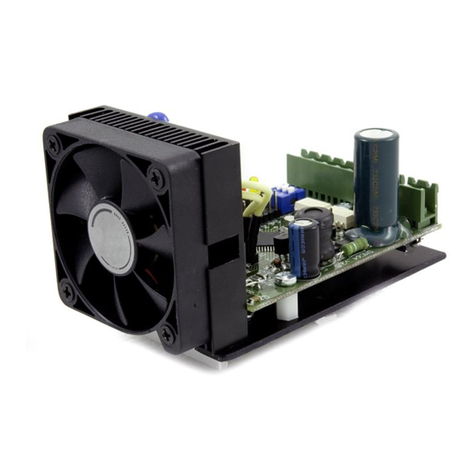
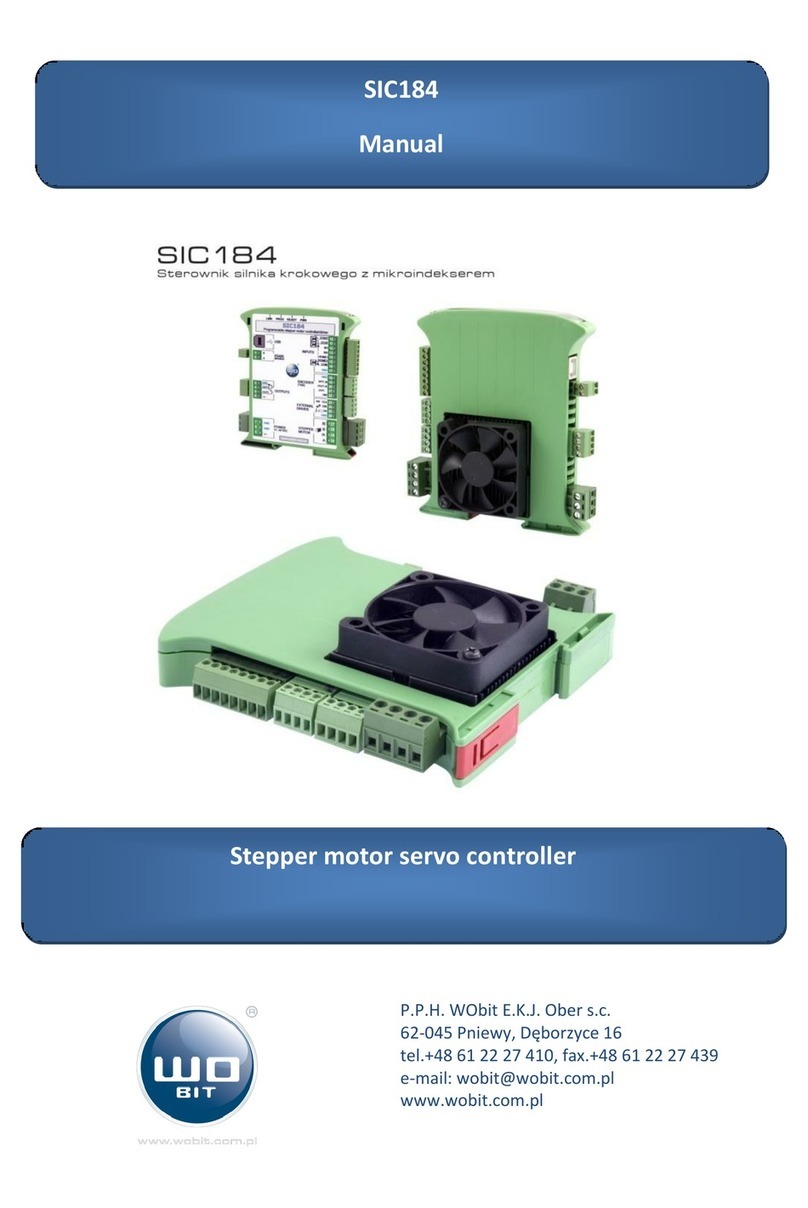
WOBIT MIC488 User manual

P.P.H. WObit E.K.J. Ober s.c.
62-045 Pniewy, Dęborzyce 16
tel. 61 22 27 422, fax. 61 22 27 439
www.wobit.com.pl
MIC488
USER MANUAL
Programmable motion
trajectory controller for 4 axis

www.wobit.com.pl
User manual MIC488 –16.07.2015r. v.1.25
page 2
Thank you for selecting our product!
This instruction will help you at correct service and accurate exploitation of described device.
Information included in this instruction were prepared with high attention by our specialists and is description of the product. Based on the
information should not be inferred a certain features or suitability for a particular application. This information does not release the user
from the obligation of own judgment and verification. P.P.H. WObit E.K.J. Ober s.c. reserves the right to make changes without prior notice.
Please read instructions below carefully and adhere to its recommendation
Please pay special attention to the following characters:
CAUTION!
Not adhere to instruction can cause damage or impede the use of hardware or software.
CAUTION!
The warranty does not cover mechanical or electrical damages caused by overvoltage, short circuit and fault
or break down caused by defective exploitation of the user/purchaser.

www.wobit.com.pl
User manual MIC488 –16.07.2015r. v.1.25
page 3
Contents
1. Safety and assembly rules............................................................................................................................................................4
1.1 Safety rules.......................................................................................................................................................................................4
1.2 Assembly recommendation..............................................................................................................................................................4
2. Device description .......................................................................................................................................................................5
2.1 Designation ......................................................................................................................................................................................5
2.2 Functions..........................................................................................................................................................................................6
3. Equipment description.................................................................................................................................................................7
3.1 Connectors and indicating lamps layout ..........................................................................................................................................7
3.2 Power supply....................................................................................................................................................................................8
3.3 Universal inputs IN1…IN8.................................................................................................................................................................8
3.4 Universal inputs IN9…IN22 / for encoders .......................................................................................................................................8
3.5 Universal outputs OUT1…OUT8 .......................................................................................................................................................9
3.6 Outputs for M1…M4......................................................................................................................................................................10
3.7 Connection example.......................................................................................................................................................................10
4. Software MIC488-PC..................................................................................................................................................................11
4.1 Connection MIC488 with PC via USB..............................................................................................................................................11
4.2 Program description.......................................................................................................................................................................12
5. Driver configuration...................................................................................................................................................................13
5.1 Initial information –motion parameters........................................................................................................................................13
5.2 Drives configuration .......................................................................................................................................................................14
5.2.1 Homing and motion limiting mode............................................................................................................................................16
5.2.2. Position control with encoder ...................................................................................................................................................17
5.2.3. Configuration example ..............................................................................................................................................................17
5.2.4. Control of drive status ...............................................................................................................................................................19
5.3. Digital inputs configuration ............................................................................................................................................................19
5.4. Analog inputs configuration ...........................................................................................................................................................20
5.5. RS232/RS485 communication configuration..................................................................................................................................20
6. Manual control and diagnostics .................................................................................................................................................21
6.1 Drives manual control ....................................................................................................................................................................21
6.2. Diagnostics .....................................................................................................................................................................................22
6.3 Errors signalization .........................................................................................................................................................................22
7. Driver programming ..................................................................................................................................................................23
7.1 Introduction ...................................................................................................................................................................................23
7.2. WBCprog program description.......................................................................................................................................................24
7.2.1 Main window..................................................................................................................................................................................24
7.2.2 Saving and opening a project .........................................................................................................................................................25
7.2.3 Quick commands menu ........................................................................................................................................................25
7.2.4 Position table .................................................................................................................................................................................26
7.2.5 Sending file to the driver................................................................................................................................................................26
7.2.6 Running and testing of the program ..............................................................................................................................................27
7.3. WBL language description..............................................................................................................................................................28
8. Program example in WBCprog ...................................................................................................................................................30
8.1 Use of inputs / outputs...................................................................................................................................................................30
8.2. Read out of analog inputs (0-10V)..................................................................................................................................................31
8.3. Control of drives.............................................................................................................................................................................31
8.3.1 Linear interpolation........................................................................................................................................................................32
8.3.2 Circular interpolation .....................................................................................................................................................................33
8.4. Readout / Save of encoder position ...............................................................................................................................................34
8.5. Timers.............................................................................................................................................................................................35
8.6. Mathematical operations and variable ..........................................................................................................................................35
8.7 Interrupts .......................................................................................................................................................................................35
8.8 Program example ...........................................................................................................................................................................36
9List of commands and registers..................................................................................................................................................37
7MODBUS communication ..........................................................................................................................................................39
8Record of changes......................................................................................................................................................................39
9Technical parameters.................................................................................................................................................................40
10 Declaration of conformity..........................................................................................................................................................42

www.wobit.com.pl
User manual MIC488 –16.07.2015r. v.1.25
page 4
1. Safety and assembly rules
1.1 Safety rules
Prior to first start-up of the device please refer to this manual and keep it for further use.
Provide appropriate working conditions in compliance with the device specification ( e.g.: power supply
voltage, temperature, maximum current consumption).
Protect inside of the device from any liquids or elements –it can cause electric shock and damage of the
device.
Basic features which knowledge and use will provide safe use consonant with its designation will be
demonstrate on the device or in this manual.
The device with its parts is manufactured in way to provide its safe mounting and connection.
The device is designed and manufactured as to conform to the principles of protection against the threats
mentioned above provided that the device is used in a manner consistent with its purpose and that it is
properly maintained.
The device can cause interference of sensitive radio and television devices in nearby.
1.2 Assembly recommendation
It is recommended to follow measures described below to prevent any possible interruptions of the device
operation:
Do not power the driver on the same line as the device without a corresponding high power line filters
(drivers/servo motors).
Minimize influence of external interference.
To minimize noises please use screening of the supply, sensor and signal cables or use twisted pair cables
(separate kink for A and B phase). It is recommended to use a ferrite bead assumed on the motor wire in
close to the driver.
Please avoid leading signal cables (CLK, DIR, EN) parallel or in close to electrical and power wire of the
motor; signal cables should be possibly short.

www.wobit.com.pl
User manual MIC488 –16.07.2015r. v.1.25
page 5
2. Device description
2.1 Designation
MIC488 is a programmable 4-axle driver. Its main function is to control 4 stepper or servo motors in CLK/DIR
mode.
The controller allows to connect incremental encoder for master position control. Except of universal I/O and two
0-10 V inputs the driver is equipped with RS232, RS485 interfaces operating in MODBUS (slave) protocol which
enables connection with e.g. HMI panels.
Dedicated software allows easy configuration of motors motion trajectory and to create programs for control of
driver, outputs and respond on inputs state or values of communications variable. Creation of motion programs is
made intuitively by text commands.
MIC488 can replace a traditional programmable driver (PLC) in applications where precise control of several
drives is required.
Features:
Control of up to 4 drives by CLK –DIRECTION –ENABLE outputs
Linear and circular interpolation
Possibility of execution of motion programs from driver memory (6 programs x 1000 commands)
20 digital inputs (8 opt insulated)
Option of connection up to 4 incremental encoders for master position control
8 transistor outputs
2 analog inputs 0-10 V
2 COM ports (RS232, RS485)
MODBUS-RTU communication
USB connector for programming

www.wobit.com.pl
User manual MIC488 –16.07.2015r. v.1.25
page 6
Power supply 12…26 VDC, current consumption 50 mA@24 V
Intuitive software for driver configuration and programming
2.2 Functions
Main function of MIC488 driver is control of 4 drives in CLK/DIR mode. The controller is generating motion
trajectory which includes ramp (acceleration, constant velocity, braking) to achieve smooth motion without lose
of position.
It is also possible to connect encoders for master control of motor position and for its correction by elimination
errors of motor positioning. It is useful in case of control of stepper motors which sometimes can lose position.
Encoder also gives information of mechanical stop of the drive.
MIC488 is equipped with universal inputs and outputs useful for motion program execution for controlling and
responding for signal from external devices.
Drives control:
Precise control of up to 4 drives
Automatic conversion of motion units from pulses into e.g. mm.
Control of motion ramp (acceleration, constant velocity, braking).
Set velocity mode (absolute or relative).
Set position mode (absolute or relative).
Homing mode based on proximity sensors/ encoder.
Master position control mode with use of encoder.
Control of external devices by digital outputs
Respond on external signals:
Digital inputs for signals from proximity sensors, encoders and controlling signals.
Communication by MODBUS-RTU protocol for direct control of driver and driver functions and access
to memory used by programs.
Readout pulses from encoders.
Programs execution form driver memory:
Option of programming up to 6 independent programs consisting of 1000 commands each.
Option of programming up to 8 independent „data banks” including 225 defined positions for each of
4 drives.
Simple commands executing free motion functions of selected drive.
Function of time delay, waiting for inputs, jumps and conditions.
Option of condition nesting.
Mathematic functions (addition, subtraction, multiplication, division).
Floating point support.
Access to user memory by MODBUS registers.
Programming of the driver is made by MIC488-PC application which allows to:
Configuration of selected drives.
Manual motion setting for driver.
Fast position setting for driver (JOG mode).
Readout of drive operation state, current position and velocity.
Preview of driver inputs/outputs.
Preview of value in user MODBUS registers.
Adding of current drive position to position table.
Creating motion programs and its testing (preview of currently executed program line).

www.wobit.com.pl
User manual MIC488 –16.07.2015r. v.1.25
page 7
3. Equipment description
3.1 Connectors and indicating lamps layout
Picture. 1 Description of connectors and indicating lamps MIC488 driver.
No.
Name
Description
1
RX
Data receiving
RS232 Interface
2
TX
Transmitting
3
GN
Ground
4
A
Signal +
RS485 Interface
5
B
Signal -
6
GN
Ground
Analog inputs
7
5V
Output +5V (max. 100mA)
8, 9
A1,A2
Analog inputs 0…10V
10…17
I1..I8
Universal inputs IN1…IN8
Inputs IN1..IN9
18, 19
M-
Ground for inputs IN1..IN8
20…27
O1..O8
Transistor outputs (max. 200mA/output)
28, 29, 30
GND (GN)
Ground
Driver power supply
31
VDC+
Power supply 12…26 VDC
32, 37, 42, 47
+5
Encoder power supply output +5V (max. 75mA/output)
Power supply and
encoder inputs
ENC1..ENC4
33, 38, 43, 48
GN
Ground
34
C (IN9)
Input of encoder C channel 1 / IN9 input
35
B (IN10)
Input of encoder B channel 1 / IN10 input
36
A (IN11)
Input of encoder A channel 1 / IN11 input
…
52, 56, 60, 64
GN
Ground
Driver control
outputs M1..M4
53, 57, 61, 65
EN
Output of driver operations enable signal (ENABLE)
54, 58, 62, 66
DIR
Output of direction signal (DIR)
55, 59, 64, 67
CLK
Output of step signal (CLK)
POWER
Signalization of driver power supply
RUN
Signalization of program execution from driver
memory
COM
Signalization of MODBUS communication
ERROR
Signalization of driver error

www.wobit.com.pl
User manual MIC488 –16.07.2015r. v.1.25
page 8
3.2 Power supply
Driver power supply
Driver can be supplied by 12…26 V DC voltage. For 24 V voltage supply current consumption is about 50 mA.
Power supply should be connect to VDC+ clamps and GND (31, 30).
In case of use transistor outputs you should take in consideration current consumption for outputs.
CAUTION!
Driver power supply should be independent from drives power supply. Additionally at using servo drives
supplied from the same grid you should equip it in proper supply filters to eliminate noises that can
influence on motor operation.
Output +5V
Driver facilitate +5 V voltage which can be used for supplying encoders (TTL type) or external potentiometers
connected to AIN1/AIN2 inputs. Maximal current consumption for all +5 V outputs can’t exceed 400 mA.
CAUTION!
Do not clench +5V outputs with ground (GND/GN) or power supply. It can cause damage of the driver.
Please avoid leading cables with +5V signal near to other signals causing noises.
3.3 Universal inputs IN1…IN8
Universal opt insulated inputs IN1…IN8 allows connection of external controlling signals or signals from proximity
sensors for M1…M4 drives. Input is activated by 24 V voltage (min. 5 V, max. 26 V). Common signal (negative) for
IN1...IN8 inputs is M- inputs (18,19 clamps).
Picture. 2 Opt insulated inputs (IN1 … IN8)
Parameters:
Opt insulation
High state: 24 VDC (min 5 V, max. 26 V)
Low state: < 2 VDC
3.4 Universal inputs IN9…IN22 / for encoders
IN9…IN22 inputs can be used as universal inputs or for encoders (for connection with incremental encoders).
Inputs have no insulation, common signal (negative) is ground of driver power supply GND (GN). Additionally next
to inputs are located voltage outputs +5 V which can be used for direct supply of encoders TTL 5 V type.

www.wobit.com.pl
User manual MIC488 –16.07.2015r. v.1.25
page 9
Picture. 3 Example of controlling external inputs by 24 V
signals.
Picture. 4 Example of controlling of inputs with use of +5 V voltage.
Picture. 5 Example of connection encoder with
outputs TTL type.
Picture. 6 Example of connection of
encoder with outputs Push-Pull type.
Picture. 7 Example of connection
encoder with outputs
OC type.
If controlling of drive with position control (from encoder) isn’t operate correctly (e.g. drive pass set
position) please exchange A and B signals of encoder.
3.5 Universal outputs OUT1…OUT8
Universal outputs OUT1…OUT8 allows control of external executive elements which current consumption not
exceed 200 mA. Outputs in active state give driver voltage supply VDC+. Common signal for outputs is driver
supply ground GND (28, 29, 30, 31 clamps).

www.wobit.com.pl
User manual MIC488 –16.07.2015r. v.1.25
page 10
Picture. 8 Outputs OUT1..OUT8
Parameters:
transistor outputs OC type (open collector)
load 200 mA/output
protection from inductive load
protection from overload/ short circuit (>300 mA)
high state: voltage supply VDC+
CAUTION!
Outputs are equipped with overload and short circuit protection which is activated after exceeding 300 mA
current by some of outputs. Activation of protection cause turning off of all outputs and lighting red diode
OUT ERROR. To restore output operations please remove reason of overload and reset the device.
3.6 Outputs for M1…M4
Outputs M1…M4 (signals: EN –enable, DIR –direction, CLK –step) are used for control of stepper motors or servo
drives in CLK-DIR mode. Cables shouldn’t be lead in nearby of motor cables or supply cables. It is recommended
to shield cables.
Picture. 9 Outputs M1..M4 for drives control
Parameters:
High state 5 V, low state 0 V, max. 20 mA
CLK signal (step) –max. frequency 64 kHz, pulse width 10 µs
3.7 Connection example
On picture below is presented signals connection example to MIC488. The driver is controlling one M1 drive. Hash
mark indicates optional connection of incremental encoder for additional position control (for M1 drive encoder
should be connected to ENC1 encoder channel).
Furthermore was used two inputs IN1 and IN2 for driver limit signal (KL and KR) and one OUT3 output for
activation of an external circuit (e.g. signalizing lamp, relay etc.).

www.wobit.com.pl
User manual MIC488 –16.07.2015r. v.1.25
page 11
Picture. 10 Example of connection signals to controller.
4. Software MIC488-PC
4.1 Connection MIC488 with PC via USB
Configuration and programming of the driver is made by MIC488-PC application. Driver can be connected with PC
using USB or RS232 (connection to COM1 port of the driver). It is recommended to use RS232 connection at
applications where strong noises can occur (e.g. controlling of AC servomotors).
USB connection
The driver should be connected with PC by USB cable type A –B mini. After connecting with the computer it is
permitted to turn on the supply of the driver and to run MIC488-PC software. Correct communication will be
signalized by information in program upper window.
CAUTION!
1) USB connection should be done always before turning on driver power supply.
2) USB connection is susceptible to noises in supply grid and to electromagnetic noises, existing in
industrial conditions. In case of problems with communication it is recommended to use
additional protection elements like:
Use of power line filter,
Use a high quality USB cable with length < 1,5m equipped with ferrite beads
Use of opt insulated USB HUBs on PC side
At higher noises can occur that communication won’t be possible.
MIC488 is communicating using USB port (1.1, 2.0).
There are known compatibility issues of USB 3.0 port (blue socket) at Windows 7 system while
communication with USB HID devices. In case of problems with communication please connect driver to

www.wobit.com.pl
User manual MIC488 –16.07.2015r. v.1.25
page 12
USB 2.0. port.
Serial connection RS485 (COM0)
COM0 port of MIC488 driver allows connection with PC using USB<->RS485 converter.
Signals from RS485 converter (A, B) should be connected to A and B signals of COM0 port of the driver.
To establish connection at MIC488-PC program please select on toolbar Connection -> Settings. At open window
select COM0 connection. If number COM port on PC side is known please select this port and set baudrate
(57600) then press button Connect. If number is unknown please press Search button.
Picture. 1 Window of communication settings with PC.
MIC488-PC program should be run as admin (by right-click on program icon and selecting „Run as
administrator”option). In other case program may not detect installed COM ports.
4.2 Program description
Basic program functions are available at main window tabs showed below:
Picture. 2 Toolbar.
1) Toolbar
2) Signalization of connection with the driver.
3) Running of diagnostic window with I/O preview and position of M1/M2 drives
4) Tab for manual control of drives
5) Tab with driver settings
6) Tab for creating motion programs
7) Tab with preview of user registers
Toolbar:

www.wobit.com.pl
User manual MIC488 –16.07.2015r. v.1.25
page 13
Connection –configuration of driver connection with program
Configuration –record and readout of driver settings from a file. Restore of factory settings of the driver.
Add-ons –I/O preview [this function is also available at button (3) ], Preview of X/Y [this function is also
available at button (3)], JOG control (this function is also available at „Manual control”),
Options –general settings of MIC488-PC application.
Info –information about MIC488-PC program.
5. Driver configuration
5.1 Initial information –motion parameters
While setting velocity or position for drives the driver is generating ramp (acceleration/braking)
to achieve smooth motion. There are considered parameters as below:
Parameter
Description
Units
VmaxMX
Max velocity at set position mode.
While motion to new position the velocity will not be exceeded.
[j/s]
AccMX
Acceleration for speeding up at set position mode.
Acceleration for speeding up and braking at set velocity mode.
[j/s2]
DecMX
Acceleration for braking at set position mode.
[j/s2]
where: X –means number of individual driver (1…4), j – motion unit dependent on drive configuration (e.g.. rpm etc.)
Ramp for set position
Speeding up: start of motion from 0 velocity up to velocity set by VmaxMX parameter (max. velocity for
position) with AccMX acceleration.
Constant velocity VmaxMX(only when target distance will be longer than distance need for speed up and
braking with set AccMX and DecMX parameters).
Braking: decrease of velocity to 0 with DecMX delay as far as reaching target position.
While setting of position in dependence on acceleration value for speeding up and braking the driver can reach
max. velocity if total distance need for speeding up and braking will be shorter than left set distance. Picture. 11
shows case of reaching of max. velocity whereas Picture. 12 shows ramp with limited velocity to Vreal velocity.
Picture. 11 Example of position ramp –Vmax velocity possible to achieve.

www.wobit.com.pl
User manual MIC488 –16.07.2015r. v.1.25
page 14
Picture. 12 Example of position ramp –Vmax velocity not possible to achieve.
Remarks:
Setting of position cause motion always from zero velocity.
Setting of new position during motion will cause stopping of the driver and motion from zero velocity.
This situation can cause loose of position for stepper motor while operating without encoder.
Setting of position during motion to a position will cause setting a new velocity with ramp AccMX (for
braking or speeding up to set velocity).
Ramp for set velocity
Picture. 13 Example of ramp for set velocity.
Remarks:
Ramp for velocity(for speeding up and braking) is made always with AccMX parameter.
During motion it is not possible to change AccMX parameter. New AccMX value is considered while
motion from zero velocity.
Setting of new velocity during motion will cause reaching new velocity in view of AccMX ramp.
5.2 Drives configuration
Configuration of drives is made at tab Configuration-> Drives.

www.wobit.com.pl
User manual MIC488 –16.07.2015r. v.1.25
page 15
Picture. 14 Configuration window –drives settings.
1) Drive selection for configuration (M1… M4).
2) Copying of settings between drives.
3) Configurator facilitating setting drives parameters.
4) Readout of setting from the driver (concerns all device settings).
5) Record of settings to the driver (concerns all device settings).
Parameters for drive configuration:
No.
Parameter
Description
0
UNIT
Setting of motion units displayed at program (has no influence on calculated values).
1
GEAR
Calculator pulses into unit. It defines quantity of pulses, which driver has to generate to drive
execute one motion unit.
2
MOTRES
Quantity of motor pulses per full mechanical or electrical reverse (for linear motors). Parameter
required for operations with encoder.
3
ENCRES
Encoder resolution
Defines quantity of pulses from encoder per full revolution.
CAUTION: Entered resolution value should be multiplied by 4 (consideration of square wave signal)
4
ENCOFFS
Default encoder value after reset.
5
HOME
Defines drive homing mode (precise description at 5.2.1 chapter)
6
LIMIT
Settings consider control of end drive positions by proximity sensors:
OFF –no control of end position
KL –control of left end position (for drive motion towards decreasing of position)
KR –control of right end position (for drive motion towards increasing position)
KL + KR –control of both end positions
7
HOME_KL
Setting left input for homing sensor (also for position control).
8
HOME_KR
Setting right input for homing sensor (also for position control).
9
POSCTR
Position control mode from encoder:
OFF –position control from encoder turned off
ENCODER –position control from encoder turned on
ECFOLLOW –not available
10
ERRCTR
Reaction to detection stop of drive (only for operation with encoder):
OFF –no reaction
ERRMODE0 –stop of drive, change of drive status (PosMX = M_POS_ERR)
ERRMODE1 –do. +break of executed program
ERRMODE2 –do. + turning on OUT8 output
11
KP
Reinforcement of position regulator.
It defines reinforcement of position regulator for position control from encoder mode. The bigger
value the faster position setting after lost of step. Default 50.
- setting required in case of operation with encoder for drive position control.

www.wobit.com.pl
User manual MIC488 –16.07.2015r. v.1.25
page 16
For facilitating drive configuration is used window started by button in which in next steps are given
required parameters.
Picture. 15 Drive Configurator window.
After entering parameters please press „Calculate coefficient ->”button and then click on OK button. After
closing window entered parameters will be add to drive settings. To enter settings in driver please press „Save to
device”button.
Running of configurator do not cause loading of current drive settings.
5.2.1 Homing and motion limiting mode
Driver allows setting two input signals (for each drive independently) which can be used for homing and/or for
limiting end positions during motion.
Signals named as KL (homing or motion limiting during motion towards negative direction (decreasing of position)
and KR (in opposite direction).
Picture. 16 End signals and motion directions of the drive.
Homing of the drive can be made in one of modes listed below, set in HOME setting:
HOME0: Simple homing. Stop of the drive is made instantly after reaching proximity sensor.
HOME1: Precise homing mode 1. Drive is reaching proximity sensor (mounted in end position), stops and
then slowly move back up to signal decline from sensor (back in front of sensor).
HOME2: Precise homing mode 2. Drive is reaching proximity sensor (mounted in end position), stops and
then slowly forward move until signal decline from sensor (drive across sensor).

www.wobit.com.pl
User manual MIC488 –16.07.2015r. v.1.25
page 17
HOME3: Encoder homing mode 1. Drive is reaching a mechanical blockage then stops, and then slowly
move back up to detecting signal from encoder C channel (INDEX).
HOME4: Encoder homing mode 2. Drive is reaching proximity sensor, stops and then slowly move back
up to detecting signal from encoder C channel (INDEX).
For HOME1 up to HOME4 mode reverse motion is made with 20% of homing velocity.
Limiting of position by end signal is configured by LIMIT setting. The drive stops when it detects end signal. Then
possible is only move in opposite direction. Do not set the same input when two end signals are active (KL+KR
mode) –it will cause blocking of drive operation after sensor activation.
It is also possible to limit position using program (LimL and LimR registers are available by Modbus or WBCprog
program). By default this registers store maximal range values of positions.
5.2.2. Position control with encoder
MIC488 can control motor position based on external encoder connected to ENC inputs (ENC1…4 for next drives
M1…M4). Way of encoder connection is presented at Błąd! Nie można odnaleźć źródła odwołania. chapter.
For proper operation encoder with motor it is necessary to enter correct parameters MOTRES (it defines number
of motor pulses per full revolution) and ENCRES (it defines number of encoder pulses per full revolution).
For example:
For stepper motor with 1,8° step and driver with step resolution 1/64 MOTRES will be equal to 200*64 =
12800
For encoder with 400 resolution ENCRES will be equal 4 * 400 = 1600 (multiply x 4 to respect square wave
signal of encoder).
After entering parameters please test drive by setting for example absolute position = 1. Then following situations
are possible:
Drive behavior
Description
Execution of full revolution.
Parameters and encoder connection are correct.
Drive executes full revolution then reverse.
Too small encoder resolution was entered (e.g. square wave wasn’t
taken under consideration) or too high motor resolution.
Drive will execute more than full
revolution and stops.
It was entered too high resolution of encoder or too small resolution of
motor.
Drive will execute full revolution and will
continue operation without stopping.
Incorrectly connected encoder or motor. Please exchange one of
motor phases (e.g. A with /A) or encoder channels (A with B)
Drive will execute full revolution but while
losing of position its correction is made
very slowly.
Please increase value of position regulator KP.
5.2.3. Configuration example
At configuration example as a driver was used stepper motor (with step 1,8° that means 200 step/revolution),
controlled by driver with 1/64 step resolution. Motor is driving a ball screw with lead 5 mm/revolution. For
position control were used two sensors –left as homing sensor and for limiting motion and right as sensor
limiting motion on the right side. Homing can be made precisely with reaching of sensor position and leasing up
to signal decline from sensor. Control unit is mm.

www.wobit.com.pl
User manual MIC488 –16.07.2015r. v.1.25
page 18
Picture. 17 Exemplary configuration of a drive (operations without encoder).
Configuration (without encoder)
Motor driver is connected to M1 output of MIC488. Sensor KL signal is connected to IN1 input and KR signal to
IN2 input. In M1 drive settings (tab Konfiguracja -> Napędy -> M1) (tab Configuration ->Drives -> M1) enter
parameters as below:
(0) UNIT: mm
(1) GEAR: 64 * 200 / 5 mm = 2560
(5) HOME: HOME1
(6) LIMIT: KL + KR
(7) HOME_KL: IN1
(8) HOME_KR: IN2
Other parameters are insignificant for operation without encoder.
You can also use drive calculator (by pressing Configurator button). After its activation enter necessary
parameters:
1) Type of motion: linear,
2) Units: mm,
3) Type and drive parameters: stepper motor, step resolution 1/64, motor step 200 (1,8°),
4) Transmission ratio: 5 mm.
Picture. 18 Drive Configurator window with entered parameters.
Then press „Calculate coefficient ->” button. After closing of configurator by „OK” button, settings will be enter
into window with M1 drive parameters.
After entering settings please press „Save to device” button to send settings to the driver.
Configuration (with encoder)
At this case to drive was add an incremental encoder with resolution 400 ppr. There was also deleted right end
proximity sensor.

www.wobit.com.pl
User manual MIC488 –16.07.2015r. v.1.25
page 19
Picture. 19 Exemplary configuration of a drive (operations with encoder).
Please enter parameters as below:
(0) UNIT: mm
(1) GEAR: 64 * 200 / 5 mm = 2560
(2) MOTRES: 64*200 = 12800
(3) ENCRES: 400 * 4 = 1600 (x4, because it should be considered encoder
square wave signal)
(4) ENCOFFS: 0 (default position after reset)
(5) HOME: HOME1
(6) LIMIT: KL
(7) HOME_KL: IN1
(8) HOME_KR: OFF
(9) POSCTR: ENCODER
(10) ERRCTR: 1 (it defines driver reaction in case of drive mechanical stop).
(11) KP: should be set experimentally. Default value is 50.
If controlling of drive with position control (from encoder) is not operate correctly (e.g. drive pass set
position) please exchange A with B signals of encoder.
5.2.4. Control of drive status
Drive status can be controlled using:
Information at manual control window,
MODBUS registers: M1_STATUS (1010)… M4_STATUS (1013)
Registers at WBCprog: StatM1…StatM4
At table below are presented values of status register and corresponding it drive states.
Register value
Description
0
Drive turned off (signal EN = 0)
1
Drive turned on but not in motion ( EN signal active)
2
Drive is in set velocity mode
3
Drive is in motion to set position mode
4
Drive achieved set position
5
Error of achieving set position (for operation with encoder)
6
Drive at homing mode
7
-
8
Drive at position correction mode (for operation with encoder)
9
Drive achieved final L position while motion towards negative direction (by
program, or by activation of proximity sensor signal KL)
10
Drive achieved end R position while motion towards positive direction (by
program or by activation of proximity sensor signal KR)
5.3. Digital inputs configuration
Configuration consider only IN1…IN8 inputs used in program as universal inputs. Settings has no influence on
inputs operation in drive position/homing function.

www.wobit.com.pl
User manual MIC488 –16.07.2015r. v.1.25
page 20
Picture. 20 Inputs settings.
No.
Name
Description
0
IO_FILTER
Level of input filtration. It defines minimal time for giving signal on input to keep it active.
1
IO_LEVEL
It defines what level is a high state for input.
HIGH level means that input is active after giving voltage on input.
LOW level means that input is active while no signal on input.
5.4. Analog inputs configuration
Picture. 21 Settings of analog inputs.
No.
Name
Description
0
AIN_LOVAL
Value for input signal 0V
1
AIN_HIVAL
Value for input signal 10V
Settings allows to scale voltage input signal 0…10 V into other value which can be used in motion program for e.g.
direct control of drive velocity etc.
For example for input voltage 0V AIN value is -25 and for 10V +25. Then should be entered:
AIN_LOVAL: -25
AIN_HIVAL: +25
5.5. RS232/RS485 communication configuration
Picture. 22 Setting of RS232/RS485 communication.
Table of contents
Other WOBIT Controllers manuals
Popular Controllers manuals by other brands

Rain Bird
Rain Bird ESP-TM Series Installation, Programming, & Operation

Progres
Progres Agronic 7000 installation manual

BFT
BFT ALCOR N installation manual

LSI
LSI LSI53C1030 Technical manual

BFT
BFT HIDE SL SMART BT A300 Installation and user manual

Weinzierl
Weinzierl KNX IP LineMaster 760 OPERATING AND INSTALLATION Manual