Wolf IM15/S User manual

INSTALLATION INSTRUCTIONS
MULTI-FUNCTION COOKTOP

As you follow these instructions, you will
notice WARNING and CAUTION symbols.
This blocked information is important for the
safe and efficient installation of Wolf equip-
ment. There are two types of potential
hazards that may occur during installation.
Another footnote we would like to identify is
IMPORTANT NOTE: This highlights informa-
tion that is especially relevant to a problem-
free installation.
signals a situation where minor injury or
product damage may occur if you do not
follow instructions.
states a hazard that may cause serious
injury or death if precautions are not
followed.
WOLF®is a registered trademark of Wolf Appliance Company, LLC

3
INSTALLATION REQUIREMENTS
IMPORTANT NOTE: This installation must
be completed by a qualified installer,
service agency or gas supplier.
IMPORTANT NOTE:
Save these Installation
Instructions for the local inspector’s use.
Please read the entire Installation Instruc-
tions prior to installation.
Installer:
please retain these instructions
for local inspector’s reference, then leave
them with the homeowner.
Homeowner:
please read and keep these
instructions for future reference and be
sure to read the entire Use & Care Infor-
mation prior to use.
IMPORTANT NOTE:
This appliance must be
installed in accordance with National Electri-
cal Codes, as well as all state, municipal and
local codes. The correct voltage, frequency
and amperage must be supplied to the appli-
ance from a dedicated, grounded circuit
which is protected by a properly sized circuit
breaker or time delay fuse. The proper
voltage, frequency, and amperage ratings are
listed on the product rating plate.
Record the model and serial numbers before
installing the cooktop. Both numbers are
listed on the rating plate, located on the
underside of the cooktop.
Model Number IM15/S
Serial Number
WOLF MULTI-FUNCTION COOKTOP
CONTACT
INFORMATION
Wolf Customer
Service:
800-332-9513
Website:
wolfappliance.com
IMPORTANT NOTE:
Installation and service must be
performed by a qualified installer,
service agency or the gas supplier.
Warranty service must be performed
by a Wolf authorized service center.
Do not store or use gasoline or
other flammable vapors and liquids
in the vicinity of this or any other
appliance.
Aventilation hood or downdraft
system is recommended for use
with the Wolf gas multi-function
cooktop.
WHAT TO DO IF YOU SMELL GAS:
Do not try to light any appliance.
Do not touch any electrical switch.
Do not use any phone in your
building.
Immediately call your gas supplier
from a neighbor’s phone. Follow the
gas supplier’s instructions.
If you cannot reach your gas
supplier, call the fire department.
If the information in this book is
not followed exactly, a fire or
explosion may result, causing
property damage, personal injury
or death.

BEFORE YOU START
Proper installation is your responsibility.
Have a qualified technician install this
cooktop. You must also ensure that electri-
cal installation is adequate and in compli-
ance with all local codes and ordinances.
The Wolf multi-function cooktop is manu-
factured for use with
natural gas
or
LP
gas
.Please check the product rating plate
for type of gas needed.
Proper gas supply connection must be
available; refer to Gas Supply Requirements
on page 8. Electrical ground is required; see
Electrical Requirements on page 10.
Check the location where the cooktop will
be installed. The location should be away
from strong draft areas, such as windows,
doors and strong heating vents or fans. Do
not obstruct flow of combustion and
ventilation air.
Make sure you have everything necessary
for correct installation. It is the responsibil-
ity of the installer to comply with the instal-
lation clearances specified on the product
rating plate. The rating plate can be found
on the underside of the cooktop.
4
This cooktop is intended for indoor use.
COMMONWEALTH OF MASSACHUSETTS
Installations and repairs must be performed
by a qualified or licensed contractor,
plumber or gas fitter qualified or licensed
bythe state, province, or region where this
appliance is being installed.
Use only gas shut-off valves approved for
use within the state, province, or region
where this appliance is being installed.
Aflexible gas connector, when used, must
not exceed 3' (.9 m).
WOLF MULTI-FUNCTION COOKTOP

5
Dimensions in parentheses are in
millimeters unless otherwise specified.
INSTALLATION INSTRUCTIONS
INSTALLATION SPECIFICATIONS
The illustrations below provide the overall
dimensions, installation specifications and
countertop cut-out for Model IM15/S.
Ifthe cooktop is not installed above an oven,
the gas service may be supplied through the
floor. When an oven is installed below the
cooktop, unless you are using cabinets deeper
than 24" (610), it is recommended that the elec-
trical supply be placed in the base cabinet to
the right of the oven. Refer to the Installation
Specifications illustration below for specifics on
placement of the electrical and gas supply.
IMPORTANT NOTE:
When multiple cooktops
and/or modules are installed side by side, refer
to the countertop cut-out dimensions on page 7.
E
5" (127)
G
15"
(381)
15"
(381)
33" (838)
RECOMMENDED
CABINET WIDTH
LOCATION OF GAS SUPPLY
MAY ALSO EXTEND 5" ON
FLOOR FROM BACK WALL
5"
(127)
LOCATION OF GAS
SUPPLY MAY ALSO
EXTEND 5" ON FLOOR
FROM BACK WALL
NOTE: Application shown allows for installation of two 15" (381) modules side-by-side.
*Minimum 24" (610) from protected cabinet or 30" (762) from unprotected cabinet to countertop.
**Minimum clearance from side and rear edge of cooktop cut-out to combustible surface up to 18" (457) abovecountertop.
191/4"(489)
COOKTOP CUT-OUT
DEPTH
21/2"min
(64)
14" (356)
CUT-OUT
WIDTH
18"
(457)
7"**
(178)
18"
(457)
7"**
(178)
24" OR 30"*
(610 or 762)
TO COUNTERTOP
36" (914)
STANDARD
FLOOR TO
COUNTERTOP
HEIGHT
21/2"**
(64)
15" (381)
OVERALL WIDTH
21"
(533)
OVERALL
DEPTH
5" (127)
MODEL IM15/S DIMENSIONS
Overall Width 15" (381)
Overall Height 5" (127)
Overall Depth 21" (533)
Minimum Cabinet Depth 223/4"(578)
Minimum Height Clearance* 5" (127)
Cut-Out Width 14" (356)
Cut-Out Depth 191/4"(489)
*For additional information on minimum height
clearance, see Countertop Cut-Out Dimensions on
page 6.
Dimensions may vary to ±1/8"(3).
Overall Dimensions
Installation Specifications and
Countertop Cut-Out Dimensions
FRONT OF COUNTERTOP
21/2"min
(64)
191/4"(489)
COOKTOP
CUT-OUT DEPTH
14" (356)
COOKTOP
CUT-OUT
WIDTH
Model IM15/S
Multi-Function
Cooktop

6
Dimensions in parentheses are in
millimeters unless otherwise specified.
WOLF MULTI-FUNCTION COOKTOP
SITE PREPARATION
LOCATION REQUIREMENTS
The following minimum dimensions must be
maintained when installing the Wolf gas
multi-function cooktop, Refer to the Installation
Specifications illustration on page 5.
Minimum horizontal clearance from the
sides and back of the cooktop cut-out to
adjacent vertical combustible construction,
extending a minimum of 18" (457) above
the countertop, 7" (178) from side edges
of cut-out and 21/2"(64) from rear edge of
cut-out.
Minimum 24" (610) clearance between the
countertop and the bottom of a wood or
metal cabinet which is protected by not less
than 1/4"(6) flame retardant millboard
covered with not less than No. 28 MSG
sheet steel, .015" (.4) stainless steel, or
.024" (.6) aluminum or .02" (.5) copper.
Minimum 30" (762) clearance between the
countertop and the bottom of an unpro-
tected wood or metal cabinet.
IMPORTANT NOTE:
When installing a ventila-
tion hood, refer to the specific requirements
of the hood for the minimum dimension to
countertop.
COUNTERTOP CUT-OUT DIMENSIONS
IMPORTANT NOTE:
Countertop opening
dimensions shown in the Installation Specifica-
tions illustration on page 5 must be used.
The dimensions shown provide for required
clearances.
The multi-function cooktop is designed to fit a
standard 24" (610) deep base cabinet with a
25" (635) deep countertop. Before making the
countertop cut-out, verify that the cooktop will
clear the side walls of the base cabinet below.
There should be at least 51/2"(140) clearance
between the countertop and any combustible
surface directly below the unit.
If the cabinet has a drawer,a51/2"(140) clear-
ance from the countertop to the top of the
drawer (or other obstruction) in the base
cabinet is required. A 15" (381) or less drawer
depth may be needed to avoid interfering with
the gas pressure regulator.
IMPORTANT NOTE:
When multiple cooktops
and/or modules are installed side by side,
refer to the countertop cut-out dimensions on
page 7.
Failure to locate the cooktop without the
proper clearances will result in a fire
hazard.

7
INSTALLATION INSTRUCTIONS
INSTALLATION OPTIONS
MULTIPLE COOKTOP INSTALLATION
Ifthe multi-function cooktop is to be used with
any combination of additional cooktop units or
modules with a filler strip, the cut-out width is
calculated by adding the corresponding units'
cut-out dimensions plus 11/4"(32) for each
additional unit. Refer to the illustration below.
IMPORTANT NOTE:
When multiple cooktops
and/or modules are installed side by side, each
unit must have its own separate recommended
electrical circuit. When multiple gas cooktops
and/or modules are installed next to one
another, they can receive their gas supply from
acommon line. However, each unit
MUST
have its own gas pressure regulator installed
between the mainline and the cooktop or
module.
When two or moremodules areinstalled
together,an integrated module filler strip
(IFILLER/S) is required. If a downdraft ventila-
tion system is also installed, an integrated
module supportfor downdraft ventilation
(ISUPPORT) is also required. Contact your Wolf
dealer for information on these accessory
components.
21/2"min
(64)
FRONT OF COUNTERTOP
191/4"
(489)
CUT-OUT
DEPTH
291/4"(743)
TWO MODULES WIDTH
441/2"(1130) THREE MODULES WIDTH OR
441/4"(1124) 30" COOKTOP AND ONE MODULE
593/4"(1518) FOUR MODULES WIDTH OR
591/2"(1511) 30" COOKTOP AND TWO MODULES OR
501/4"(1276) 36" COOKTOP AND ONE MODULE
14"
(356)
CUT-OUT
WIDTH
Countertop cut-out dimensions for installation of multiple cooktops
and/or modules
OPTIONAL
INSTALLATIONS
Dimensions will
vary according to
the specific
installation.
IMPORTANT NOTE:
Refer to specific
installation requirements and limitations for
each integrated module. Review specific
installation instructions for product to product
capabilities. Additional information is provided
onour website, wolfappliance.com

8
WOLF MULTI-FUNCTION COOKTOP
IMPORTANT NOTE:
The gas multi-function
cooktop must be connected to a regulated gas
supply.
IMPORTANT NOTE:
This installation must
conform with local codes and ordinances. In
the absence of local codes, installations must
conform with American National Standard,
National Fuel Gas Code ANSI Z223.1 – latest
edition or CANI – B149.1 or 2.
IMPORTANT NOTE:
The natural gas multi-
function cooktop (Model IM15/S) is rated for
elevations up to 8,000' (2438 m) without
adjustment. Install a high altitude kit for eleva-
tions from 8,000' (2438 m) to 10,000' (3084 m).
The LP gas multi-function cooktop (Model
IM15/S-LP) is rated for up to 10,000' (3084 m).
EXPLOSION HAZARD—
Use a new CSA approved gas supply line
and install a gas shut-off valve.
Securely tighten all gas connections.
For LP gas, have a qualified technician
make sure the gas pressure does not
exceed 14" (34.9 mb) WC (water column).
Failure to do so can result in explosion,
fire or death.
GAS SUPPLY REQUIREMENTS
The gas multi-function cooktop is equipped for
use with natural or LP gas. It is design certified
bythe Canadian Standards Association (CSA)
for natural or LP gases. The product rating
plate, located on the underside of the cooktop,
has information on the type of gas that should
be used. If this information does not agree
with the type of gas available, contact your
Wolf dealer. To obtain local dealer information,
visit the Locator section of our website,
wolfappliance.com.
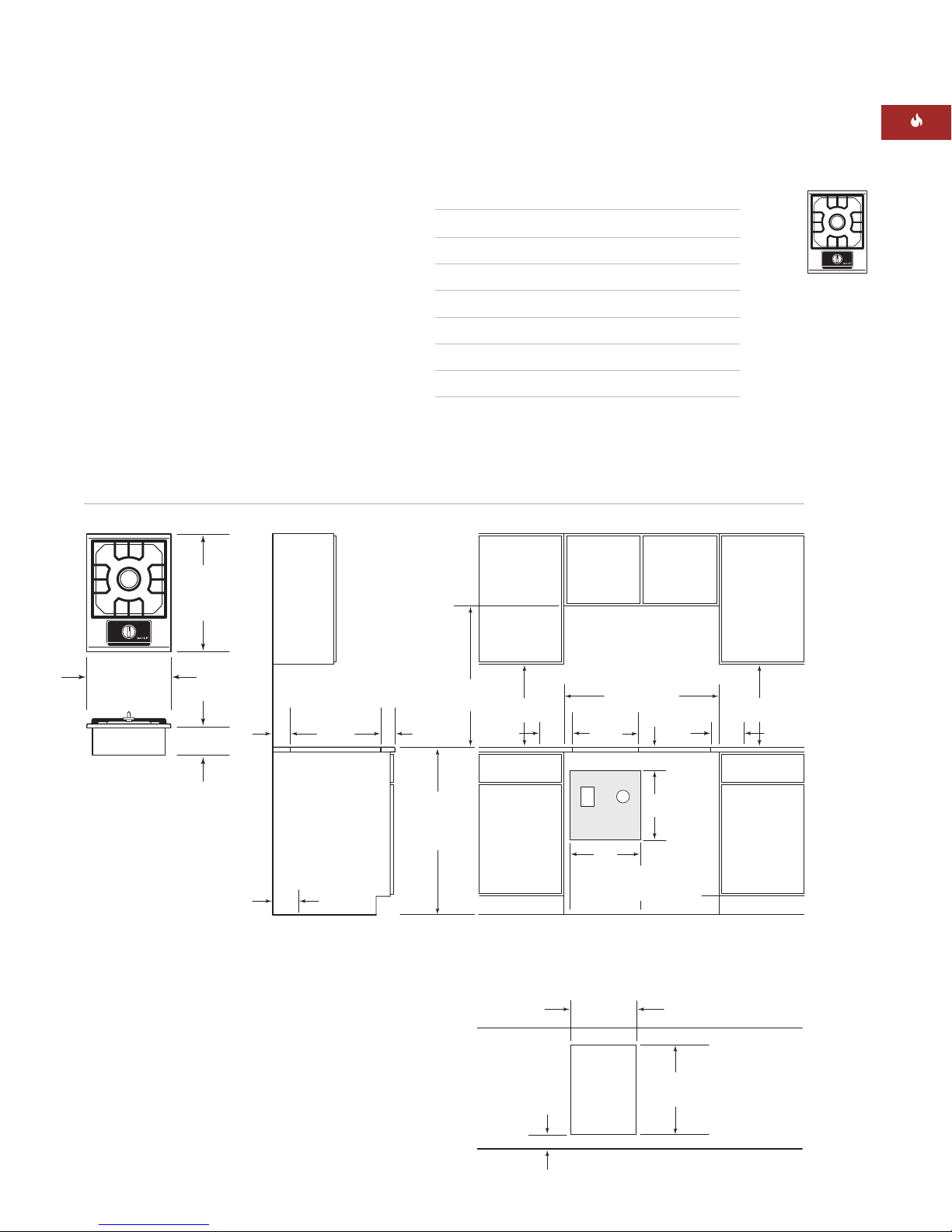
The gas multi-function cooktop is supplied
with a 1/2"NPT male gas connection at the
right rear corner of the cooktop.
Provide a gas supply line of 3/4"rigid pipe to
the cooktop location. A smaller size pipe on
long runs may result in insufficient gas supply.
Pipe joint compounds, suitable for use with LP
gas should be used. For LP gas, piping or
tubing size can be 1/2"minimum.
If local codes permit, a new CSA design-
certified, 4–5' (1.2–1.5 m) long, 1/2"or 3/4"ID,
flexible metal appliance connector is recom-
mended for connecting this cooktop to the gas
supply line. Do not kink or damage the flexible
connector when moving the cooktop. The gas
pressure regulator has 1/2"female pipe threads.
You will need to determine the fittings
required, depending on the size of your gas
supply line, flexible metal connector and shut-
offvalve.
If rigid pipe is used as a gas supply line, a
combination of pipe fittings must be used to
obtain an in-line connection to the cooktop. All
strains must be removed from the supply and
gas lines so the cooktop will be level and in
line.
8

9
Dimensions in parentheses are in
millimeters unless otherwise specified.
INSTALLATION INSTRUCTIONS
GAS SUPPLY REQUIREMENTS
IMPORTANT NOTE:
The supply line must
be equipped with an approved external gas
shut-off valve located near the cooktop in an
accessible location. Do not block access to the
shut-off valve. Refer to the illustration below.
The inlet pressure to the regulator should be
asfollows for operation and checking the regu-
lator setting:
Natural Gas:
Set pressure 5" (12.5 mb) WC,
supply pressure 7–14" (17.5–34.9 mb) max.
LP Gas:
Set pressure 10" (25 mb) WC,
supply pressure 12–14" (29.9–34.9 mb) WC.
LINE PRESSURE TESTING
Testing above .5 psi (3.5 kPa) 14" (34.9 mb)
WC (gauge):
The cooktop and its individual
shut-off valve must be disconnected from
the gas supply piping system during any
pressure testing of that system at test pres-
sures greater than .5 psi (3.5 kPa).
Testing below .5 psi (3.5 kPa) 14" (34.9 mb)
WC (gauge) or lower:
The cooktop must be
isolated from the gas supply piping system
by closing its individual manual shut-off
valve during any pressure testing of the gas
supply piping system at test pressures
equal to or less than .5 psi (3.5 kPa).
IMPORTANT
NOTE
This installation
must conform with
local codes and
ordinances. In the
absence of local
codes, installations
must conform with
the American
National Standard,
National Fuel Gas
Code and National
Electrical Code
regulations.

10
WOLF MULTI-FUNCTION COOKTOP
CONTACT
INFORMATION
Copies of the
standards listed
may be obtained
from:
*National Fire
Protection
Association
Batterymarch Park
Quincy,
Massachusetts
02269
**Canadian
Standard
Association
178 Rexdale Blvd.
Etobicoke
(Toronto), Ontario
M9W 1R3
ELECTRICAL SHOCK HAZARD—
Plug into a grounded 3-prong electrical
outlet.
Do not remove ground prong.
Do not use an adapter.
Failure to follow these instructions can
result in electric shock, fire or death.
Electronic ignition systems operate within
wide voltage limits, but proper ground and
polarity are necessary. In addition to checking
that the electrical outlet provides 120 VAC
power and is correctly grounded, the outlet
must be checked by a qualified electrician to
see if it is wired with correct polarity.
Awiring diagram covering the control circuit
for the Wolf multi-function cooktop model can
be found on page 15.
RECOMMENDED GROUND METHOD
IMPORTANT NOTE:
For your personal safety,
this cooktop must be grounded. It is equipped
with a 6' (1.8 m) power cordwith 3-prong
grounding plug. Tominimize possible shock
hazard, the power cord must be plugged into
a3-prong ground-type electrical outlet,
grounded in conformance with the National
Electrical Code, ANSI/NFPA 70 latest edition*,
or Canadian Electrical Code (CSA)** and all
local codes and ordinances.
If an electrical outlet is not available, it is the
obligation of the customer to have a properly
grounded, 3-prong electrical outlet installed by
aqualified electrician.
IMPORTANT NOTE:
If codes permit and a
separate ground wire is used, it is recom-
mended that a qualified electrician determine
that the ground path is adequate.
IMPORTANT NOTE:
Check with a qualified
electrician if you arenot surewhether the
cooktop is properly grounded.
IMPORTANT NOTE:
Do not ground to a gas
pipe.
A120 VAC, 60 Hz, 15-amp, fused electrical
supply is required. A time-delay fuse or circuit
breaker is recommended. It is recommended
that a separate circuit serving only this appli-
ance be provided.
IMPORTANT NOTE:
Aground fault circuit
interrupter (GFCI) is not recommended and
may cause interruption of operation.
ELECTRICAL REQUIREMENTS
Grounding Plug
Grounding-Type
Electrical Outlet
Electrical ground

11
Dimensions in parentheses are in
millimeters unless otherwise specified.
INSTALLATION INSTRUCTIONS
VENTILATION OPTIONS
IMPORTANT NOTE:
It is recommended that
you operate the Wolf multi-function cooktop
with either a Wolf cooktop ventilation hood,
downdraft system or Pro ventilation hood.
Contact your Wolf dealer for details.
Cooktop Wall Hood –
30" (762) or 36" (914)
widths in classic stainless steel.
Cooktop Island Hood –
42" (1067) width in
classic stainless steel.
Downdraft Ventilation System –
30" (762)
or 36" (914) widths, with top cover and
control panel in classic, platinum and
carbon stainless steel finishes (adequate
countertop depth is required).
Pro Wall Hood –
22" (559), 24" (610) or 27"
(686) depths and 30" (762) to 66" (1676)
widths in classic stainless steel.
Pro Island Hood –
36" (914) to 66" (1676)
widths in classic stainless steel.
Pro Hood Liner –
available in widths to
accommodate 30" (762) to 60" (1524) hood
shells.
All hoods have welded seams, sealed halogen
lighting, and removable, dishwasher-safe
filters.
Blower requirements may vary due to the
length of ducting and number of angles. The
basic recommendation is 100 CFM per square
foot of cooking area. Always consult your
HVAC professional for more concise blower
requirements.
IMPORTANT NOTE:
When installing a ventila-
tion hood, refer to the specific requirements
of the hood for the minimum dimension to
countertop.
VENTILATION
PRODUCTS
Wolf ventilation
products are
available through
your Wolf dealer.
You can also visit
the Locator section
of our website,
wolfappliance.com,
for names of local
dealers in your
area or go to the
Product section
to obtain
additional product
information.

COOKTOP INSTALLATION
Insert the cooktop into the countertop cut-out
opening. Center the cooktop in the opening
and make sure that the front edge of cooktop
is parallel to the front edge of the countertop.
Check that all required clearances are met. Use
apencil to outline the rear edge of the cooktop
on the countertop. Remove the cooktop from
the countertop opening.
IMPORTANT NOTE:
When repositioning the
cooktop in the countertop cut-out opening, lift
the entire cooktop up from the opening to
prevent scratching the countertop.
Remove the foam strip from the hardware
package. Apply the foam strip around the
bottom of the burner box flush with the edge
as shown in the illustration below.
Reinsert the cooktop into the countertop
opening. Check that the cooktop is parallel to
the front edge of the countertop. Lift the entire
cooktop to make adjustments and align the
rear edge with the pencil line.
Attach the brackets to the burner box by insert-
ing the clips into the rectangular punchouts on
the left and right side of the burner box. Insert
the 31/2"(89) clamping screws into the
brackets. Use a screwdriver to tighten the
clamping screws against the underside of the
countertop. Refer to the illustration below.Do
not overtighten screws.
12
GAS PRESSURE REGULATOR
Install the gas pressure regulator with the
arrow on the regulator pointing up toward the
unit and in a position where you can reach the
access cap. Refer to the illustration below.
Anatural gas and LP compatible pipe-joint
compound should be used to ensure a gas-
tight seal.
IMPORTANT NOTE:
All connections must be
wrench-tightened. Do not make connections to
the gas pressure regulator too tight; this may
crack the regulator and cause a gas leak. Do
not allow the regulator to turn on the pipe
when tightening fittings.
GAS SUPPLYLINE CONNECTION
Assemble the flexible metal connector from
the gas supply pipe to the gas pressure regula-
tor. You will need to determine the fittings
required, depending on the size of your gas
supply line, flexible metal connector and shut-
off valve. Refer to the illustration on page 13.
Use a pipe-joint compound made for use with
natural and LP gas. If a flexible metal connec-
tor is used, be surethe tubing is not kinked.
Open the shut-off valve in the gas supply line.
Wait a few minutes for the gas to move
through the line. Refer to the illustration on
page 9.
Cooktop
Burner Box
Foam
Strip
Burner Box
31/2"(89)
Clamping
Screw
Countertop
Bracket
Clip
Foam strip application Bracket installation
WOLF MULTI-FUNCTION COOKTOP
Rear of
Cooktop
Pressure
Regulator
Access
Cap
Gas Flow –
Arrow
Points Up
Gas pressure regulator

13
Dimensions in parentheses are in
millimeters unless otherwise specified.
INSTALLATION INSTRUCTIONS
GAS LEAK TESTING
Use a brush and liquid detergent to test all gas
connections for leaks. Bubbles around connec-
tions will indicate a leak. If a leak appears, shut
off gas valve controls and adjust connections.
Then check connections again. Clean all the
detergent solution from the cooktop.
COMPLETING THE INSTALLATION
Once the cooktop has been checked for any
gas leaks, plug the power supply cord into the
grounded electrical outlet.
Place the burner head on the burner base and
position the burner grate over the burner
assembly.
IMPORTANT NOTE:
Do not seal the cooktop
to the countertop. It must be removed if
service is necessary.
1/2"Nipple
(use pipe-joint
compound on ends)
1/2" Nipple
(use pipe-joint
compound on ends)
Pressure
Regulator
1/2" Adapter 1/2" Adapter
Shut-Off
Valve
Flexible Metal
Connector
Gas supply line connection
SURFACE BURNERS
INITIAL LIGHTING
The cooktop burner uses an electronic igniter
in place of a standing pilot. When the cooktop
control knob is pushed in and turned to the
HIGH position, the system creates a spark to
light the burner. This sparking continues until
the electronic ignition senses a flame.
To check operation of the cooktop burner, push
in and turn the control knob to the HIGH
position. The flame should light within four
seconds.
If the burner does not light properly, turn the
control knob to the OFF position. Check that
the burner head is in the proper position.
Check that the power supply cordis plugged in
and that the circuit breaker or house fuse has
not blown. Make sure that the shut-off valve is
in the ON position. Check operation again; if
the burner does not light properly at this point,
contact a Wolf authorized service center.
IMPORTANT NOTE:
Initial lighting of the
cooktop burner may take slightly longer as air
in the system must be purged before gas can
be supplied to the burner.
Never test for a gas leak with a match or
other flame.

14
CONTACT
INFORMATION
Wolf Customer
Service:
800-332-9513
Website:
wolfappliance.com
IF YOU NEED SERVICE
If service is necessary, maintain the quality
built into your multi-function cooktop by
calling a Wolf authorized service center.
Toobtain the name and number of a
Wolf authorized service center, check
the Locator section of our website,
wolfappliance.com
orcall Wolf Customer
Service at
800-332-9513
.
When calling for service, you will need the
cooktop model and serial numbers. Both
numbers are listed on the rating plate,
located on the underside of the cooktop.
WOLF MULTI-FUNCTION COOKTOP
The information and images are the copyright
property of Wolf Appliance Company, LLC, an
affiliate of Sub-Zero Freezer Company, Inc.
Neither this book nor any information or images
contained herein may be copied or used in whole
or in part without the express written permission
of Wolf Appliance Company, LLC, an affiliate of
Sub-ZeroFreezer Company,Inc.
©Wolf Appliance Company, LLC all rights reserved.
COOKTOP REMOVAL
If it is necessary to remove the multi-function
cooktop for cleaning or service, shut off the
gas supply. Disconnect the gas and electric
supply. Remove the mounting brackets on the
right and left side of the burner box and
remove the cooktop. Reinstall in the reverse
order and check the gas connection for leaks.
TROUBLESHOOTING
IMPORTANT NOTE:
If the cooktop does not
operate properly, follow these troubleshooting
steps:
Verify that power is being supplied to the
cooktop.
Check thatgas valves are turned to the ON
position.
Check the gas supply and electrical
connections to ensure that the installation
has been completed correctly.
Follow troubleshooting procedures as
described in the Wolf Multi-Function
Cooktop Use & CareInformation.
If the cooktop still does not work, contact
a Wolf authorized service center.Do not
attempt to repair the cooktop yourself. Wolf
is not responsible for service required to
correct a faulty installation.

15
INSTALLATION INSTRUCTIONS
N
A
11
22
BLACK
BLACK
WHITE
WHITE
RED
WHITE
RED
WHITE
RED
SPARK
MODULE 3 CONDUCTOR
POWER CORD
GRN
BLK
8
Model IM15/S
WIRING DIAGRAM

807568 10/2005
WOLF APPLIANCE COMPANY, LLC P. O. BOX 44848 MADISON, WI 53744 800-332-9513 WOLFAPPLIANCE.COM
Other manuals for IM15/S
6
Table of contents
Other Wolf Cooktop manuals

Wolf
Wolf RH User manual

Wolf
Wolf CI243C/B User manual

Wolf
Wolf CT15G User manual

Wolf
Wolf ICBMM15TF-S User manual

Wolf
Wolf VH User manual

Wolf
Wolf CT30G/S User manual

Wolf
Wolf Sealed Burner RangeTop Owner's manual

Wolf
Wolf ICBCG152TF/S User manual

Wolf
Wolf CE304C/B/208 User manual

Wolf
Wolf ICBCT15G Owner's manual
Popular Cooktop manuals by other brands

Electro Depot
Electro Depot VALBERG EHP 2Z K 350C Instructions for use

Sencor
Sencor SCP 4201GY Translation of the original manual

Frigidaire
Frigidaire FGC30C3A Factory parts catalog

Uten
Uten HP212-D Operating and safety instructions

Jenn-Air
Jenn-Air JIC4724HB Use and care guide

GE
GE ZGU660 Use and care & installation guide