Wolf Sub-Zero ICBIG15/S User manual

GRILL MODULE
INSTALLATION INSTRUCTIONS
INSTRUCCIONES DE INSTALACIÓN
INSTRUCTIONS D’INSTALLATION
ISTRUZIONI PER L’INSTALLAZIONE
INSTALLATIONSANWEISUNGEN

As you follow these instruc tions, you will
notice WARNING and CAUTION symbols.
This blocked information is impor tant for the
safe and efficient installation of Wolf equip-
ment. There are two types of potential
hazards that may occur during installation.
Another footnote we would like to identify is
IMPORTANT NOTE: This highlights informa-
tion that is especially relevant to a problem-
free installation.
signals a situation where minor injury or
product damage may occur if you do not
follow instructions.
states a hazard that may cause serious
injury or death if precautions are not
followed.
WOLF®is a registered trademark of Wolf Appliance, Inc.
CO N TA C T
I N F O R M AT I O N
Website:
wolfappliance.com

5
IN STA LL ATI ON R E Q U I R E M E N T S
IMPORTANT NOTE:
Save these Installation
Instru tions for the lo al inspe tor’s use.
Please read the entire Installation
Instru tions prior to installation.
This installation must be ompleted by a
qualified te hni ian.
Installer:
please retain these instru tions
for lo al inspe tor’s referen e, then leave
them with the homeowner.
Homeowner:
please read and keep
these instru tions for future referen e and
be sure to read the entire Use & Care
Information prior to use.
IMPORTANT NOTE:
This applian e must be
installed in a ordan e with lo al odes. The
orre t voltage, frequen y and amperage
must be supplied to the applian e from a
dedi ated, grounded ir uit whi h is prote ted
by a properly sized ir uit breaker or time
delay fuse. The proper voltage, frequen y,
and amperage ratings are listed on the
produ t rating plate.
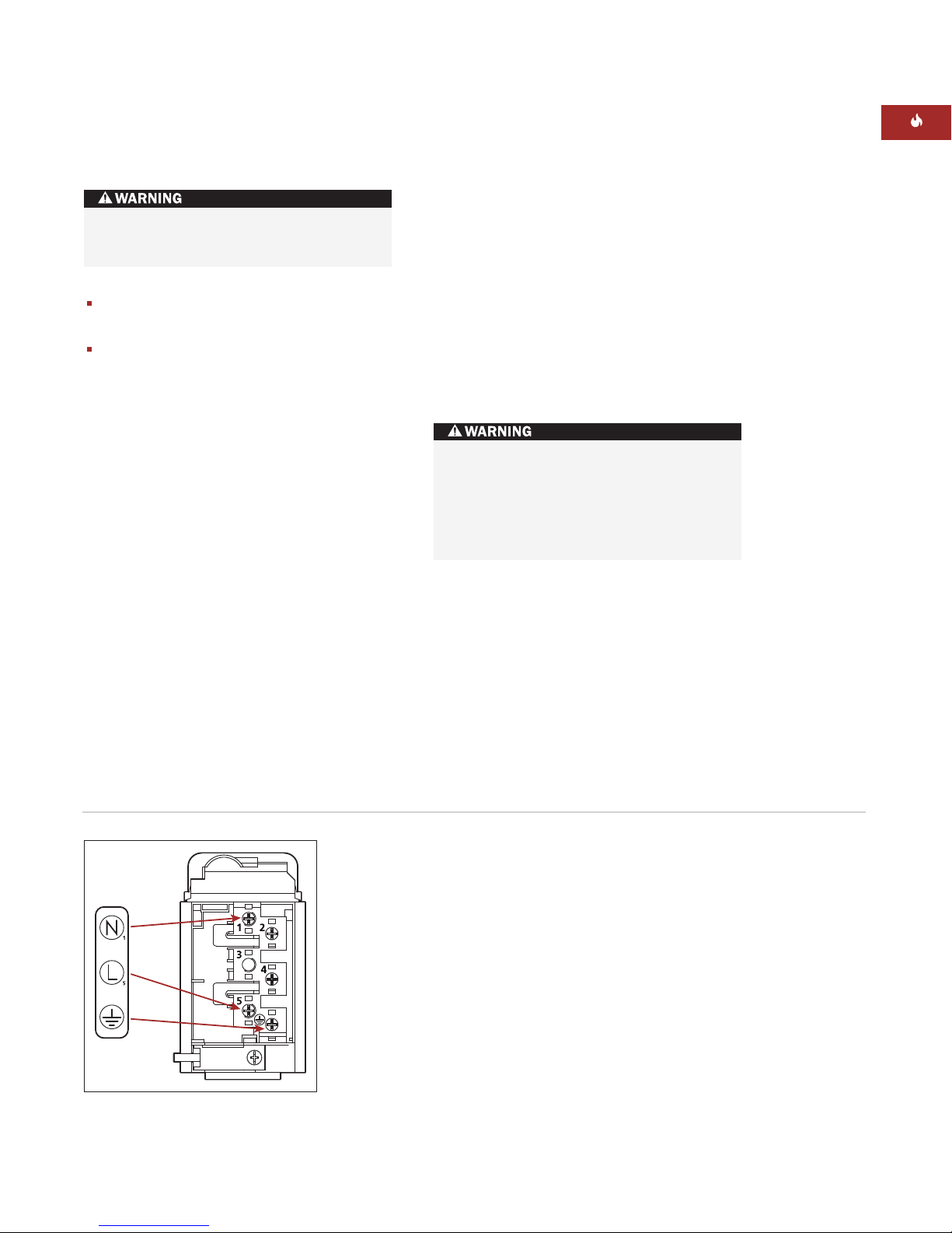
Re ord the model and serial numbers before
installing the grill module. Both numbers are
listed on the produ t rating plate lo ated on
the underside of the module. Refer to the
illustration below.
IMPORTANT NOTE:
Conne tion of this appli-
an e should be through a fused onne tion
unit or a suitable isolator, whi h omplies
with national and lo al safety regulations. The
on/off swit h should be easily a essible after
the applian e has been installed. If the swit h
is not a essible after installation (depending
on ountry) an additional means of dis on-
ne tion must be provided for all poles of the
power supply. When swit hed off there must
be an all pole onta t gap of 3 mm in the
isolator swit h. This 3 mm onta t dis onne t
gap must apply to any isolator swit h, fuses
and/or relays a ording to EN60335.
A means for dis onne tion of the ele tri al
supply must be in orporated in the fixed
wiring in a ordan e with the wiring rules.
BE FOR E YO U S TA RT
IMPORTANT NOTE:
Installation and
service must be performed by a qualified
installer or service agency.
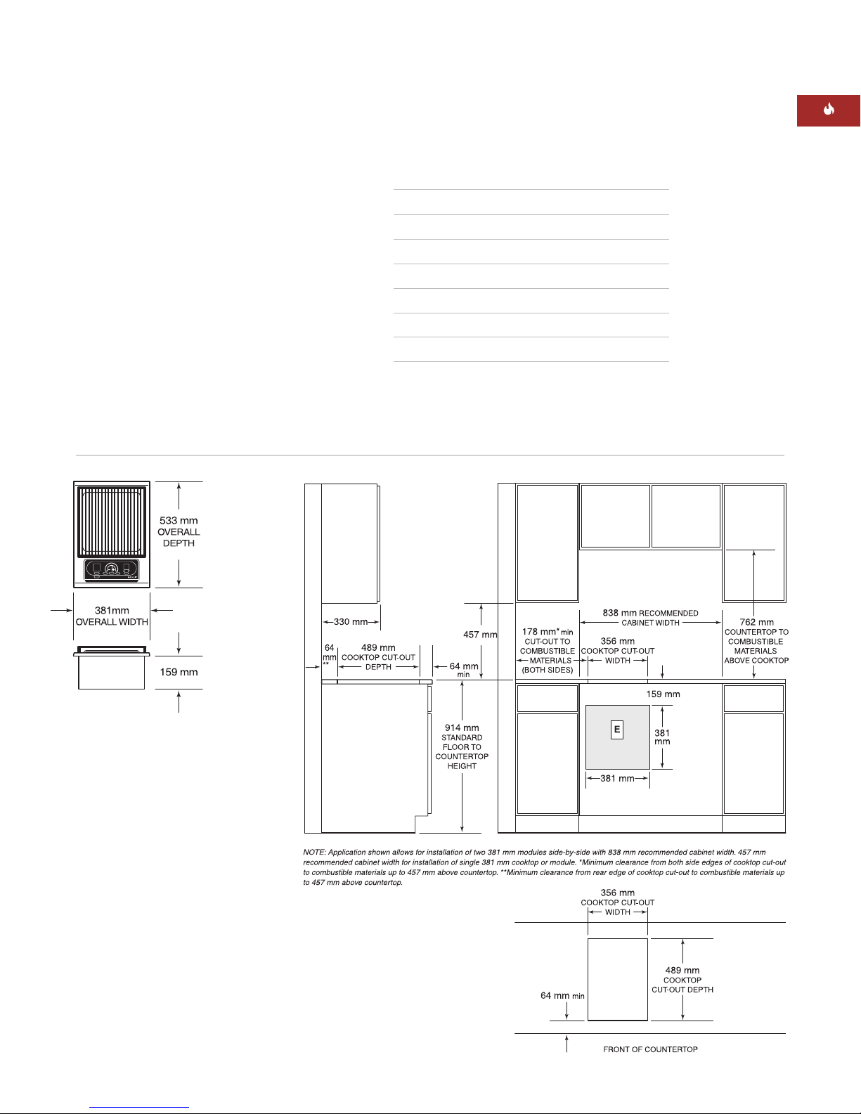
Installation of the grill module must meet
the minimum learan e requirements for
safe operation. Refer to Site Preparation
on page 6.
If the grill module is to be used with any
ombination of additional ooktop units or
modules, refer to Multiple Cooktop Installa-
tion on page 8.
Ele tri al installation must be adequate
and in omplian e with all lo al odes and
ordinan es. Ele tri al ground is required,
refer to Ele tri al Requirements on page 9.
IMPORTANT NOTE:
A ventilation hood is
re ommended (but not required) for use with
the Wolf ele tri grill module.
This module is intended for indoor use.
W O L F GR ILL MO DUL E
Model ICBIG15/S
Model Number
ICBIG15/S
Serial Number
Rating plate location
Lo ation of rating
plate under module

6
L O C AT I O N I N C O U N T E RTO P
A)
Minimum flat ountertop surfa e. Must be
equal to or greater than the width of the
module(s).
B)
Minimum 152 mm wide learan e from the
module side edge to any ombustible
surfa e up to 457 mm above the ountertop
(noted by shaded area).
O V E R H E A D C A B I N E T D I M E N S I O N S
C)
Minimum spa ing between overhead side
abinets must be greater than or equal to
the nominal width of the module(s).
D)
Minimum 457 mm verti al distan e from
the ountertop to the bottom of side
abinets within minimum side learan e.
E)
Minimum verti al distan e between the
ountertop and ombustible materials
above the module must be 762 mm.
F)
Minimum 25 mm from rear wall.
G)
Maximum 330 mm depth of overhead and
side abinets dire tly above and within side
learan e.
SI TE P R E PA R AT I O N
IMPORTANT NOTE:
Installation of the Wolf
ele tri grill module must meet the following
lo ation requirements. All dimensions listed
are minimum requirements for safe operation.
Refer to the illustration below.
To eliminate the risk of burns or fire by
reaching over heated surface units,
cabinet storage space located above the
surface units should be avoided. If
cabinet storage is to be provided, the risk
can be reduced by installing a ventilation
hood that projects horizontally a
minimum of 127 mm beyond the bottom
cabinets.
Failure to locate the cooktop module
without the proper clearances will result
in a fire hazard.
W O L F GR ILL MO DUL E
C
G
D
A
B
B
E
F
Minimum installation clearances

7
IN STA LL ATI ON S P E C I F I C AT I O N S
The illustrations below provide the overall
dimensions, finished ut-out dimensions and
ele tri al pla ement for the Wolf ele tri grill
module.
The grill module is designed to fit a standard
610 mm deep base abinet with 635 mm deep
ountertop. Before making the ountertop ut-
out, verify that the module will lear the side
walls of the base abinet below.
A grounded jun tion box needs to be pla ed
within 1.2 m of the right rear of the module.
Lo ate ele tri al with the shaded area of the
illustration below.
max
M O D E L I C B I G 1 5 / S D I M E N S I O N S
Overall Width 381 mm
Overall Height 159 mm
Overall Depth 533 mm
Minimum Cabinet Depth 578 mm
Minimum Height Clearan e 159 mm
Cut-Out Width 356 mm
Cut-Out Depth 489 mm
Unit dimensions may vary to ±3 mm.
IN STA LL ATI ON I N S T R U C T I O N S
Overall Dimensions
Installation Specifications
Countertop Cut-Out
Dimensions

8
W O L F GR ILL MO DUL E
MU LTI PLE CO OKTOP I N S TA L L AT I O N
IMPORTANT NOTE:
If the grill module is to be
used with a ombination of additional ooktop
units or modules with a filler strip, the ut-out
width is al ulated by adding the orresponding
units' ut-out dimensions plus 32 mm for ea h
additional unit.
When multiple units are installed side by side,
ea h unit must have its own separate re om-
mended ele tri al ir uit.
When two or more modules are installed
together, an integrated module filler strip
(IFILLER/S) is re ommended.
Countertop cut-out dimensions for installation of multiple cooktops
IMPORTANT NOTE:
Review spe ifi
installation instru tions for produ t to produ t
apabilities.

9
EL ECT RI C AL R E Q U I R E M E N T S
Required Power Supply
220–240 V AC, 50–60 Hz
Maximum Connected Load
2.8 kW
Lo ate ele tri al within the shaded area shown
in the illustration on page 7. A properly rated
ord should be atta hed to the power supply
box of the grill as shown in the illustration
below. Open the power box to expose the
s rews with orresponding numbers. Loosen
the 1, 5, and ground s rews. Run the ord
through the ir ular hole and into the power
supply box. Atta h the Neutral wire to the
number 1 position. Atta h the line wire to the
5 position and atta h the ground wire to the
orresponding ground s rew. After tightening
the s rews, lose the over to the power
supply box without pin hing any of the wires.
You must follow all lo al odes and ordinan es
when installing your servi e.
Attach the power cord to the unit before
plugging the cord into the wall.
IMPORTANT NOTE:
The orre t voltage,
frequen y and amperage must be supplied to
the applian e from a dedi ated, grounded
ir uit whi h is prote ted by a properly sized
ir uit breaker or time delay fuse. The proper
voltage, frequen y, and amperage ratings are
listed on the produ t rating plate lo ated on
the underside of the module. Refer to the illus-
tration on page 5. The wiring diagram overing
the ontrol ir uit is lo ated inside the module
ontrol box.
The complete appliance must be properly
grounded at all times when electrical
power is applied.
Improper connection can result in a fire
hazard!
W O L F GR ILL MO DUL E
Power supply box
IMPORTANT NOTE:
To avoid ele tri al sho k
when dis onne ting the grill module, all
poles/wires must be dis onne ted from the
power supply box.

10
M O D U L E I NS TAL L AT IO N
To prevent pollution from entering the ontrols
area, atta h the foam strip to the underside of
the module frame. Refer to the illustration
below.
Gently lower the grill module into the ut-out
area in the ountertop and enter. Che k that
the front edge of module is parallel to the front
edge of the ountertop. Che k that all required
learan es are met.
To atta h the bra kets to the sides of the
module, insert the lip into the re tangular
pun hout in the pan, and push down. Install
the lamping s rew into the bra ket and
tighten until the s rew onta ts the underside
of the ountertop. Do not overtighten s rews.
Refer to the illustration below.
IMPORTANT NOTE:
Do not use aulk or
sili one to seal the module to the ountertop.
The unit must be readily removable for
servi e.
BE FOR E O P E R AT I N G
Read the entire Wolf Grill Module Use & Care
Information in luded with the module. Impor-
tant safety, servi e and warranty information is
ontained within the book.
Thoroughly lean the grilling grate, grease
defle tion plates and grease olle tion pan
with mild soap and water before use.
Foam strip Installation brackets
IN STA LL ATI ON I N S T R U C T I O N S

11
TROUBLES H O OT I N G
IMPORTANT NOTE:
If the grill module
does not operate properly, follow these
troubleshooting steps:
Verify that power is being supplied to the
module.
Che k ele tri al onne tions to ensure that
the installation has been ompleted
orre tly.
Follow troubleshooting pro edures as
des ribed in the Wolf Grill Module
Use & Care Information.
If the module still does not work, onta t a
Wolf authorized Wolf dealer. Do not attempt
to repair the ooktop module yourself.
M O D U L E REMOVAL
IMPORTANT NOTE:
Removal of the grill
module should only be performed by a Wolf
authorized servi e enter te hni ian.
If removing the grill module is ne essary for
leaning or servi e, first dis onne t the ele tri
supply. Remove the mounting bra kets on
ea h side of module and remove. To reinstall,
refer to page 10.
The module must be disconnected from
power prior to removal and service.
W O L F GR ILL MO DUL E

12
C O N TA C T
I N F O R M AT I O N
Website:
wolfappliance.com
I F YO U N E E D S E RVIC E
For servi e in your area, onta t either your
Wolf dealer or visit the showroom lo ator
page of our website,
wolfappliance.com
to
find the regional distributor by ountry.
When alling for servi e, refer to the model
and serial number of the grill module. Both
numbers are listed on the produ t rating
plate lo ated on the underside of the
module. Refer to the illustration on page 5.
IN STA LL ATI ON I N S T R U C T I O N S
The information and images are the copyright
property of Wolf Appliance, Inc., an affiliate of
Sub-Zero, Inc. Neither this book nor any informa-
tion or images contained herein may be copied
or used in whole or in part without the express
written permission of Wolf Appliance, Inc., an
affiliate of Sub-Zero, Inc.
Wolf Appliance, Inc. all rights reserved.

WOLF APPLIANCE, INC.
PO BOX 44848
MADISON, WI 53744 USA
WOLFAPPLIANCE.COM
811417 REV-B 1/2013
Other manuals for Sub-Zero ICBIG15/S
6
Other Wolf Grill manuals

Wolf
Wolf Vulcan VCCB25 User manual

Wolf
Wolf BBQ242 User manual

Wolf
Wolf OG36 User manual

Wolf
Wolf OG54LP User manual

Wolf
Wolf Sub-Zero ICBIG15/S User manual

Wolf
Wolf Sub-Zero ICBIG15/S User manual

Wolf
Wolf OG36-LP Operating manual

Wolf
Wolf Sub-Zero ICBIG15/S User manual

Wolf
Wolf IG15/S User manual

Wolf
Wolf IG15/S User manual