Wolf 1200154 Operating instructions

MICROWAVE OVEN
Troubleshooting & Technical Data
6-2
PP
PPrr
rrii
iioo
oorr
rr
tt
ttoo
oo
SS
SSee
eerr
rrii
iiaa
aall
ll
NN
NNuu
uumm
mmbb
bbee
eerr
rr
11
1122
2200
0000
0011
1155
5544
44
TROUBLESHOOTING AND TECHNICAL DATA
This section of the manual combines the Troubleshooting Guide with Technical Data. The troubleshooting table on
the following page lists the condition and problems, as well as which parts need to be replaced or checked and
which test procedures to follow. The test procedures on the pages following the troubleshooting table contain the
appropriate technical data needed for each test.
When troubleshooting the microwave oven, it will be helpful to follow the Detailed Operating Sequence when per-
forming the checks. Many of the possible causes of trouble will require that a specific test be performed. These
tests are given a procedure letter which will be found in the "Test Procedure" portion of this troubleshooting guide.
See “How to Use This Troubleshooting Table” on following page.
Before continuing, take note of the WARNING and Important Notes below.
-MICROWAVE OVENS CONTAIN CIRCUITRYCAPABLE OF PRODUCING VERYHIGH VOLTAGE AND CUR-
RENT. CONTACT WITH THE FOLLOWING COMPONENTS MAYRESULT IN SERIOUS PERSONALINJURY
OR DEATH:
•TRANSFORMER•RECTIFIER•HIGH VOLTAGE HARNESS
•MAGNETRON•CAPACITOR
-TOAVOID ELECTRIC SHOCK DURING TROUBLESHOOTING, NEVER TOUCH ANYPART OF THE ELEC-
TRICALCIRCUIT WITH HANDS OR UNINSULATED TOOLS WHILE THE POWER IS CONNECTED.
-BEFORE SERVICING THE MICROWAVE OVEN, THE CAPACITOR MUST BE DISCHARGED BYSHORTING
THE CONNECTING LEAD OF THE RECTIFIER AGAINST THE CHASSIS WITH AN INSULATED SCREW-
DRIVER. FAILURE TO FOLLOW THIS STEPCOULD RESULT IN SERIOUS PERSONALINJURYOR
DEATH. NOTE: THE CAPACITOR REMAINS CHARGED APPROXIMATELY60 SECONDS AFTER THE
OVEN IS SWITCHED OFF. WAIT FOR 60 SECONDS, THEN SHORT THE CAPACITOR TO THE CHASSIS.
IMPORTANT NOTE: If the oven becomes inoperative because of a blown monitor fuse, defective monitor switch,
interlock switch or door sensing switch, the complete Latch Hook/Switch Assembly must be
replaced. See part #802955 in the Service Parts Price List.
IMPORTANT NOTE: When troubleshooting, it may be necessary in some cases to supply power to the unit with
the outer cabinet case removed. In this event:
1. Disconnect the power supply cord, and then remove outer cabinet case.
2. Open the door and block it open.
3. Discharge high voltage capacitor.
4. Disconnect the leads to the primary of the power transformer.
5. Ensure that the leads remain isolated from other components and oven chassis by
using insulation tape.
6. Only after performing the five steps listed above should the power supply cord be recon-
nected.
When the testing is completed:
1. Disconnect the power supply cord, then remove outer case.
2. Open the door and block it open.
3. Discharge high voltage capacitor.
4. Reconnect the leads to the primary of the power transformer.
5. Reinstall the outer cabinet.
6. Reconnect the power supply cord after the outer case is installed.
7. Run the oven and check all functions.

Troubleshooting & Technical Data
MICROWAVE OVEN
6-3
PP
PPrr
rrii
iioo
oorr
rr
tt
ttoo
oo
SS
SSee
eerr
rrii
iiaa
aall
ll
NN
NNuu
uumm
mmbb
bbee
eerr
rr
11
1122
2200
0000
0011
1155
5544
44
How to use this table:
CK = Check Parts Listed
RE = Replace Parts Listed (after verifying defects)
All other letters indicate which test procedure to be performed. Test procedures can be found in alphabetical order
on the following pages.
Home fuse or circuit breaker blows
when power cord is plugged into
wall receptacle
Monitor fuse blows when power
cord is plugged into wall receptacle.
All letters and indicators do not
appear in display when power cord
is first plugged into wall outlet.
Display does not operate properly
when STOP/CLEAR key is
touched. (Buzzer should sound and
" :" or time of day should appear
IN display.)
Oven lamp does not light when
door is opened.
Oven lamp does not go out when
door is closed.
Oven lamp lights but fan motor
and turntable motor do not operate.
Oven does not go into cook cycle
when START pad is touched
Oven seems to be operating but
little or no heat is produced in oven
load. (Food incompletely cooked or
not cooked at all at end of cook
cycle.)
Oven goes into a cook cycle but
extremely uneven heating is
produced in oven load (food).
Oven does not cook properly when
programmed for Cooking Power 5
mode. (Operates properly on
Cooking Power 10 (HIGH) mode.)
Oven goes into COMPU DEFROST
but food is not defrosted well.
AH sensor does not end during
sensor cooking condition. (Oven
does not shut off after a cup of
water is boiling by sensor cooking)
Oven stops at 16 sec. after starting.
OFF
CONDITION
PROBLEM
CONDITION
SHORT IN POWER CORD
SHORT OR OPENED WIRING
MAGNETRON
POWER TRANSFORMER
H.V. RECTIFIER ASSEMBLY
HIGH VOLTAGE CAPACITOR
CAVITY TEMPERATURE FUSE
MAGNETRON TEMPERATURE FUSE
PRIMARY INTERLOCK SYSTEM
SECONDARY INTERLOCK SWITCH
MONITOR SWITCH
MONITOR FUSE
OVEN LAMP OR SOCKET
COOLING FAN MOTOR
TURNTABLE MOTOR
TOUCH CONTROL PANEL
WRONG OPERATION
LOW VOLTAGE
DIRTY OVEN CAVITY
KEY UNIT
RELAY (RY1)
COMPU DEFROST
FOIL PATTERN ON PWB.
AH SENSOR
POSSIBLE CAUSE
AND/OR
DEFECTIVE PARTS
TEST PROCEDURE
RE RE
ACDEEFFGH
RE RE
CK
I
CKCKCK
JKL N
COOKING
CONDITION
SENSOR
COOKING
CONDITION
BM

MICROWAVE OVEN
Troubleshooting & Technical Data
6-4
PROCEDURE
LETTER COMPONENT TEST
TEST PROCEDURES
A
B
MAGNETRON ASSEMBLY TEST
1. Disconnect power supply cord and remove outer cabinet case.
2. Open door and block it open.
3. Discharge high-voltage capacitor.
4. To test for an open filament, isolate the magnetron from the high voltage circuit. A continuity check across
the magnetron filament leads should indicate less than 1 ohm.
5. To test for a shorted magnetron, connect the ohmmeter leads between the magnetron filament leads and
chassis ground. This test should indicate an infinite resistance. If there is little or no resistance the mag-
netron is grounded and must be replaced.
6. Reconnect all leads removed from components during testing.
7. Reinstall the outer cabinet case, then reconnect power supply cord.
8. Run the oven and check all functions.
NOTE:Power output of the magnetron (also referred to as Microwave output power) can be measured by per-
forming a water temperature rise test. This test should only be used if above tests do not indicate a faulty mag-
netron and there is no defect in the following components or wiring: power transformer, high voltage capacitor
and silicon rectifier. This test will require a 16 ounce (453cc) measuring cup and an accurate mercury ther-
mometer or thermocouple type temperature tester. For accurate results, the following procedure must be fol-
lowed carefully:
The following test procedure should be performed with the microwave oven fully assembled.
WARNING:HIGH VOLTAGE IS PRESENT DURING THE COOK CYCLE, SO EXTREME CAUTION SHOULD
BE OBSERVED.
1. Fill the measuring cup with 16 oz. (453cc) of tap water and measure the temperature of the water with a
thermometer or thermocouple temperature tester. Stir the thermometer or thermocouple through the water
until the temperature stabilizes. Record the temperature of the water.
2. Place the cup of water in the oven. Operate oven at POWER 10(HIGH) selecting more than 60 seconds
cook time. Allow the water to heat for 60 seconds, measuring with a stop watch, second hand of a watch or
the digital read-out countdown.
3. Remove the cup from the oven and again measure the temperature, making sure to stir the thermometer or
thermocouple through the water until the maximum temperature is recorded.
4. Subtract the cold water temperature from the hot water temperature. The normal result should be 38°F to
78°F (21°C to 42.6°C) rise in temperature. If the water temperatures are accurately measured and tested
for the required time period the test results will indicate if the magnetron tube has low power output (low rise
in water temperature) which would extend cooking time or high power output (high rise in water tempera-
ture) which would reduce cooking time. Because cooking time can be adjusted to compensate for power
output, the magnetron tube assembly should be replaced only if the water temperature rise test indicates a
power output well above or below the normal limits. The test is only accurate if the power supply line volt-
age is 120 volts and the oven cavity is clean.
POWER TRANSFORMER TEST
1. Disconnect power supply cord and remove outer cabinet case.
2. Open door and block it open.
3. Discharge high-voltage capacitor.
4. Disconnect the primary input terminals and measure the resistance of the transformer with an ohmmeter.
Check for continuity of the coils with an ohmmeter. On the R x 1 scale, the resistance of the primary coil
should be less than 1 ohm and the resistance of the high voltage coil should be approximately 90 ohms; the
resistance of the filament coil should be less than 1 ohm.
5. Reconnect all leads removed from components during testing.
6. Reinstall the outer cabinet case, then reconnect power supply cord.
7. Run the oven and check all functions.
WARNING:HIGH VOLTAGE IS PRESENTATTHE HIGH VOLTAGE TERMINAL. DO NOTATTEMPTTO MEA-
SURE HIGH VOLTAGE AT THE FILAMENT.
PP
PPrr
rrii
iioo
oorr
rr
tt
ttoo
oo
SS
SSee
eerr
rrii
iiaa
aall
ll
NN
NNuu
uumm
mmbb
bbee
eerr
rr
11
1122
2200
0000
0011
1155
5544
44

Troubleshooting & Technical Data
MICROWAVE OVEN
6-5
PROCEDURE
LETTER COMPONENT TEST
TEST PROCEDURES
C
D
E
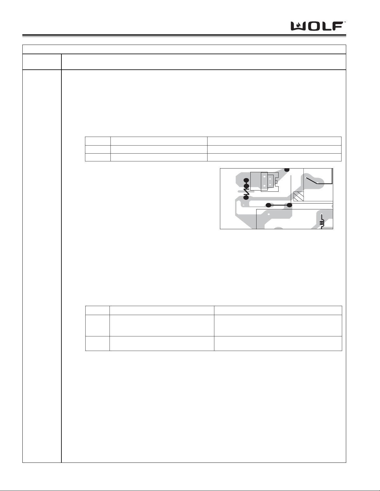
HIGH-VOLTAGE RECTIFIER TEST
1. Disconnect power supply cord and remove outer cabinet case.
2. Open door and block it open.
3. Discharge high-voltage capacitor.
4. Isolate the rectifier from the circuit. Using the highest ohm scale of the meter, read the resistance across
the terminals and observe meter reading, then reverse the leads to the rectifier terminals and observe meter
reading. If a short is indicated in both directions, or if an infinite resistance is read in both directions, the
rectifier is probably defective and should be replaced.
NOTE:Be sure to use an ohmmeter that will supply a forward bias voltage of more than 6.3 volts.
5. Reconnect all leads removed from components during testing.
6. Reinstall the outer cabinet case, then reconnect power supply cord.
7. Run the oven and check all functions.
HIGH VOLTAGE CAPACITOR TEST
1. Disconnect power supply cord and remove outer cabinet case.
2. Open door and block it open.
3. Discharge high-voltage capacitor.
4. If the capacitor is open, no high voltage will be available to the magnetron. Disconnect input leads and
check for short or open between the terminals using an ohmmeter.
Checking with a high ohm scale, if the high voltage capacitor is normal, the meter will indicate continuity for
a short time and should indicate an open circuit once the capacitor is charged. If the above is not the case,
check the capacitor with an ohmmeter to see if it is shorted between either of the terminals and case. If it is
shorted, replace the capacitor.
5. Reconnect all leads removed from components during testing.
6. Reinstall the outer cabinet case, then reconnect power supply cord.
7. Run the oven and check all functions.
CAVITY TEMPERATURE FUSE TEST
1. Disconnect power supply cord and remove outer cabinet case.
2. Open door and block it open.
3. Discharge high-voltage capacitor.
4. A continuity check across the cavity temperature fuse terminals should indicate a closed circuit unless the
temperature of the cavity temperature fuse reaches approximately 302°F (150°C). An open cavity tempera-
ture fuse indicates overheating of the oven, replace the cavity temperature fuse and check inside of oven
cavity and for improper setting of cooking time or operation of control unit. Check for restricted air flow
through the vent holes of the oven cavity, especially the cooling fan and air guide.
5. Reconnect all leads removed from components during testing.
6. Reinstall the outer cabinet case, then reconnect power supply cord.
7. Run the oven and check all functions.
MAGNETRON TEMPERATURE FUSE TEST
1. Disconnect power supply cord and remove outer cabinet case.
2. Open door and block it open.
3. Discharge high-voltage capacitor.
4. A continuity check across the magnetron temperature fuse terminals should indicate a closed circuit unless
the temperature of the magnetron temperature fuse reaches approximately 302°F (150°C). An open mag-
netron temperature fuse indicates overheating of the magnetron. Replace the temperature fuse and check
for restricted air flow to the magnetron, especially the cooling fan air guide.
5. Reconnect all leads removed from components during testing.
6. Reinstall the outer cabinet case, then reconnect power supply cord.
7. Run the oven and check all functions.
PP
PPrr
rrii
iioo
oorr
rr
tt
ttoo
oo
SS
SSee
eerr
rrii
iiaa
aall
ll
NN
NNuu
uumm
mmbb
bbee
eerr
rr
11
1122
2200
0000
0011
1155
5544
44

MICROWAVE OVEN
Troubleshooting & Technical Data
6-6
PROCEDURE
LETTER COMPONENT TEST
TEST PROCEDURES
F
G
SECONDARY INTERLOCK SWITCH TEST
1. Disconnect power supply cord and remove outer cabinet case.
2. Open door and block it open.
3. Discharge high-voltage capacitor.
4. Isolate the switch and connect the ohmmeter to the common (COM) and normally open (NO) terminal of the
switch. The meter should indicate an open circuit with the door open and a closed circuit with the door
closed. If improper operation is indicated, replace the the complete Latch Hook/Switch Assembly.
5. Reconnect all leads removed from components during testing.
6. Reinstall the outer cabinet case, then reconnect power supply cord.
7. Run the oven and check all functions.
PRIMARY INTERLOCK SYSTEM TEST
DOOR SENSING SWITCH
1. Disconnect power supply cord and remove outer cabinet case.
2. Open door and block it open.
3. Discharge high-voltage capacitor.
4. Isolate the switch and connect the ohmmeter to the common (COM) and normally open (NO) terminal of the
switch. The meter should indicate an open circuit with the door open and a closed circuit with the door
closed. If improper operation is indicated, replace the the complete Latch Hook/Switch Assembly.
5. Reconnect all leads removed from components during testing.
6. Reinstall the outer cabinet case, then reconnect power supply cord.
7. Run the oven and check all functions.
NOTE:If the door sensing switch contacts fail in the open position and the door is closed, the cooling fan,
turntable and oven light will be activated by RY1.
PRIMARY INTERLOCK RELAY (RY2)
1. Disconnect power supply cord and remove outer cabinet case.
2. Open door and block it open.
3. Discharge high-voltage capacitor.
4. Disconnect wire leads from the male tab terminals of Primary Interlock Relay. Check the state of the relay
contacts with an ohmmeter, contacts should be open. If contacts are closed, replace entire circuit board.
5. Reconnect all leads removed from components during testing.
6. Reinstall the outer cabinet case, then reconnect power supply cord.
7. Run the oven and check all functions.
MONITOR SWITCH TEST
1. Disconnect power supply cord and remove outer cabinet case.
2. Open door and block it open.
3. Discharge high-voltage capacitor.
4. Before performing this test, make sure secondary interlock switch and primary interlock relay are operating
properly. Then, disconnect wire lead from monitor switch (COM) terminal. Check monitor switch operation
with ohmmeter as follows: With door open, meter should indicate a closed circuit. With monitor switch
actuator pushed by a screw driver through the lower latch hole in oven cavity face plate and door opened
(in this condition, monitor switch plunger is pushed in), meter should indicate an open circuit. If proper oper-
ation is indicated, reconnect wire lead to the monitor switch (COM) terminal and check continuity of monitor
circuit. If monitor switch or monitor circuit indicates improper operation, replace Latch Hook/Switch
Assembly.
5. Reconnect all leads removed from
components during testing.
6. Reinstall the outer cabinet case,
then reconnect power supply cord.
7. Run the oven and check all func-
tions.
PP
PPrr
rrii
iioo
oorr
rr
tt
ttoo
oo
SS
SSee
eerr
rrii
iiaa
aall
ll
NN
NNuu
uumm
mmbb
bbee
eerr
rr
11
1122
2200
0000
0011
1155
5544
44
Monitor
Switch
Secondary Interlock Switch
Screw Driver
Ohmmeter
RED WHT/WHT

Troubleshooting & Technical Data
MICROWAVE OVEN
6-7
PROCEDURE
LETTER COMPONENT TEST
TEST PROCEDURES
H
I
BLOWN MONITOR FUSE TEST
1. Disconnect power supply cord and remove outer cabinet case.
2. Open door and block it open.
3. Discharge high-voltage capacitor.
4. If the monitor fuse is blown when the door is opened, check primary interlock relay as described earlier. If
primary interlock relay indicates proper operation, replace the the complete Latch Hook/Switch Assembly.
5. Reconnect all leads removed from components during testing.
6. Reinstall the outer cabinet case, then reconnect power supply cord.
7. Run the oven and check all functions.
TOUCH CONTROL PANEL ASSEMBLY TEST
NOTE:The touch control panel consists of circuits including semiconductors such as LSI, ICS, etc. Therefore,
unlike conventional microwave ovens, proper troubleshooting cannot be performed with only a voltmeter and
ohmmeter. In this service manual, the touch control panel assembly is divided into two units, Control Unit and
Key Unit, and the Control Unit is divided into two units, LSI Unit and Power Unit. Troubleshooting by unit
replacement is described according to the symptoms indicated.
Before Testing:
1. Disconnect power supply cord and remove outer cabinet case.
2. Open door and block it open.
3. Discharge high-voltage capacitor.
4. Disconnect the leads to the primary of the power transformer and ensure that these leads remain isolated
from other components and oven chassis by using insulation tape.
5. Re-connect the power supply cord.
KEY UNIT
1. Disconnect power supply cord and remove outer cabinet case.
2. Open door and block it open.
3. Discharge high-voltage capacitor.
4. Check Key Unit ribbon connection before replacement.
5. Reconnect all leads removed from components during testing.
6. Reinstall the outer cabinet case, then reconnect power supply cord.
7. Run the oven and check all functions.
The following symptoms indicate a defective Key Unit:
a. When touching the pads, a certain pad produces no signal at all.
b. When touching a number pad, two figures or more are displayed.
c. When touching the pads, sometimes a pad produces no signal.
If the Key unit is defective.
1. Disconnect power supply cord and remove outer cabinet case.
2. Open door and block it open.
3. Discharge high-voltage capacitor.
4. Replace the Key Unit.
5. Reconnect all leads removed from components during testing.
6. Reinstall the outer cabinet case, then reconnect power supply cord.
7. Run the oven and check all functions.
CONTROL UNIT
The following symptoms may indicate a defective control unit. Before replacing the control unit, perform the
Key Unit test (Procedure J) to determine if control unit is faulty.
a. In connection with pads.
1. When touching the pads, a certain group of pads do not produce a signal.
2. When touching the pads, no pads produce a signal.
b. In connection with indicators
1. At a certain digit, all or some segments do not light up.
2. At a certain digit, brightness is low.
3. Only one indicator does not light. (CONTINUED)
PP
PPrr
rrii
iioo
oorr
rr
tt
ttoo
oo
SS
SSee
eerr
rrii
iiaa
aall
ll
NN
NNuu
uumm
mmbb
bbee
eerr
rr
11
1122
2200
0000
0011
1155
5544
44

MICROWAVE OVEN
Troubleshooting & Technical Data
6-8
PROCEDURE
LETTER COMPONENT TEST
TEST PROCEDURES
J
(CONTINUED)
4. The corresponding segments of all digits do not light up; or they continue to light up.
5. Wrong figure appears.
6. A certain group of indicators do not light up.
7. The figure of all digits flicker.
8. The following symptoms indicate a defective LSI unit.
a. When touching the keys on the touch screen, a certain key produces no signal at all.
b. When touching a number key on the touch screen, two figures or more are displayed.
c. When touching the keys on the touch screen, sometimes a key produces no signal.
c. Other possible problems caused by defective control unit.
1. Buzzer does not sound or continues to sound.
2. Clock does not operate properly.
3. Cooking is not possible.
When testing is completed:
1. Disconnect power supply cord and remove outer cabinet case.
2. Open door and block it open.
3. Discharge high-voltage capacitor.
4. Reconnect all leads removed from components during testing.
5. Reinstall the outer cabinet case, then reconnect power supply cord.
6. Run the oven and check all functions.
KEY UNIT TEST
1. Disconnect power supply cord and remove outer cabinet case.
2. Open door and block it open.
3. Discharge high-voltage capacitor.
4. If the display fails to clear when the STOP/CLEAR pad is depressed, first verify the flat ribbon cable is mak-
ing good contact, verify that the door sensing switch (stop switch) operates properly; that is the contacts are
closed when the door is closed and open when the door is open. If the door sensing switch (stop switch) is
good, disconnect the flat ribbon cable that connects the key unit to the control unit and make sure the door
sensing switch is closed (either close the door or short the door sensing switch connecter). Use the Key
unit matrix indicated on the control panel schematic and place a jumper wire between the pins that corre-
spond to the STOP/CLEAR pad making momentary contact. If the control unit responds by clearing with a
beep the key unit is faulty and must be replaced. If the control unit does not respond, it is faulty and must
be replaced. If a specific pad does not respond, the above method may be used (after clearing the control
unit) to determine if the control unit or key pad is at fault.
5. Reconnect all leads removed from components during testing.
6. Reinstall the outer cabinet case, then reconnect power supply cord.
7. Run the oven and check all functions.
PP
PPrr
rrii
iioo
oorr
rr
tt
ttoo
oo
SS
SSee
eerr
rrii
iiaa
aall
ll
NN
NNuu
uumm
mmbb
bbee
eerr
rr
11
1122
2200
0000
0011
1155
5544
44
G 1 G 2 G 3 G 4 G 5 G 6 G 7 G 8
G 9
G10
G11
G12
G13
G14
FRESH
VEGETABLES
BEVERAGE
BREAKFAST
LUNCH
POPCORN
FROZEN
SNACKS
RECIPES
QUICK ON/
START
FISH
SEAFOOD POWER
LEVEL
KEEP
WARM
DINNER
DEFROSTHELP
BAKED
POTATOES
SENSOR
REHEAT
ADD
MINUTE
FROZEN
VEGTABLES
RICE
1
6
2
7
3
8
4
9
5
0
POULTRY
GROUND
MEAT
FROZEN
ENTREES
TIMER/
CLOCK
STOP
CLEAR

Troubleshooting & Technical Data
MICROWAVE OVEN
6-9
PROCEDURE
LETTER COMPONENT TEST
TEST PROCEDURES
K
L
RELAY TEST
1. Disconnect power supply cord and remove outer cabinet case.
2. Open door and block it open.
3. Discharge high-voltage capacitor.
4. Disconnect the leads to the primary of the power transformer and ensure that these leads remain isolated
from other components and oven chassis by using insulation tape.
5. Re-connect the power supply cord.
6. Check voltage between Pin No. 1 of the 2 pin connector (A) and the common terminal of the relay RY1 on
the control unit with an A.C. voltmeter. The meter should indicate 120 volts, if not, check oven circuit.
RY1 and RY2 RELAY TEST
NOTE:These relays are operated by D.C. voltage. Check voltage at the relay coil with a D.C. voltmeter
during the microwave cooking operation.
a. DC. voltage indicated ............. Defective relay.
b. DC. voltage not indicated ........ Check diode which is connected to the relay coil. If diode is good, control
unit is defective.
7. Disconnect power supply cord and remove outer cabinet case.
8. Open door and block it open.
9. Discharge high-voltage capacitor.
10. Reconnect all leads removed from components during testing.
11. Reinstall the outer cabinet case, then reconnect power supply cord.
12. Run the oven and check all functions.
COMPU DEFROST TEST
WARNING:THE OVEN SHOULD BE FULLYASSEMBLED BEFORE PERFORMING THE FOLLOWING PRO-
CEDURE.
1. Place one cup of water in the center of the turntable tray in the oven cavity.
2. Close the door; touch the Defrost pad and touch the number pad 5 twice; touch the start pad.
3. The oven is in Compu Defrost cooking condition.
4. The oven will operate as follows:
5. If improper operation is indicated, the control unit is probably defective and should be checked.
PP
PPrr
rrii
iioo
oorr
rr
tt
ttoo
oo
SS
SSee
eerr
rrii
iiaa
aall
ll
NN
NNuu
uumm
mmbb
bbee
eerr
rr
11
1122
2200
0000
0011
1155
5544
44
RELAY SYMBOL OPERATIONAL VOLTAGE CONNECTED COMPONENTS
RY1 Approx. 24.0V D.C. Oven lamp / Turntable motor / Cooling fan motor
RY2 Approx. 23.0V D.C. Power transformer
1ST STAGE 2ND STAGE
WEIGHT LEVEL TIME LEVEL TIME
0.5lb 70% 30sec. 40% 15sec.

MICROWAVE OVEN
Troubleshooting & Technical Data
6-10
PROCEDURE
LETTER COMPONENT TEST
TEST PROCEDURES
MFOIL PATTERN ON THE PRINTED WIRING BOARD TEST
NOTE:To protect the electronic circuits, this model is provided with a fine foil pattern added to the primary on
the PWB, this foil pattern acts as a fuse.
1. Foil pattern check and repairs.
a. Disconnect power supply cord and remove outer cabinet case.
b. Open door and block it open.
c. Discharge high-voltage capacitor.
d. Follow steps on troubleshooting table below for repair.
e. Make a visual inspection of the varistor. Check for
burned damage and examine the transformer with
a tester for the presence of layer short-circuit
(check the primary coil resistance which is approx-
imately 210 ohm ± 15%). If any abnormal condi-
tion is detected, replace the PWB.
f. Reconnect all leads removed from components
during testing.
g. Reinstall the outer cabinet case, then reconnect
power supply cord.
h. Run the oven and check all functions.
2. Follow the troubleshooting guide given below, if indicator does not light up after above check and repairs are
finished.
a. Disconnect power supply cord and remove outer cabinet case.
b. Open door and block it open.
c. Discharge high-voltage capacitor.
d. Disconnect the leads to the primary of the power transformer and ensure that these leads remain isolat-
ed from other components and oven chassis by using insulation tape.
e. After that procedure, re-connect the power supply cord.
f. Follow steps on troubleshooting table below for repair.
g. Disconnect power supply cord and remove outer cabinet case.
h. Open door and block it open.
i. Discharge high-voltage capacitor.
j. Reconnect all leads removed from components during testing.
k. Reinstall the outer cabinet case, then reconnect power supply cord.
l. Run the oven and check all functions.
PP
PPrr
rrii
iioo
oorr
rr
tt
ttoo
oo
SS
SSee
eerr
rrii
iiaa
aall
ll
NN
NNuu
uumm
mmbb
bbee
eerr
rr
11
1122
2200
0000
0011
1155
5544
44
STEPS OCCURRENCE CAUSE OR CORRECTION
1 Only pattern at "a" is broken. Replace PWB
2 Pattern at "a" and "b" are broken. Replace PWB
T1AC
VRS1
OMIF
DU
CN - A (J1)
abc
d
12
XA
VH
STEPS OCCURRENCE CAUSE OR CORRECTION
The rated AC voltage is not present between
1 Pin No. 1 of the 2-pin connector (A) and the Check supply voltage and oven power cord.
common terminal of the relay RY1.
2The rated AC voltage is present at primary Low voltage transformer or secondary circuit defective.
side of low voltage transformer. Check and repair.

Troubleshooting & Technical Data
MICROWAVE OVEN
6-11
PROCEDURE
LETTER COMPONENT TEST
TEST PROCEDURES
NAH SENSOR TEST (Checking the initial sensor cooking condition)
WARNING:THE OVEN SHOULD BE FULLYASSEMBLED BEFORE PERFORMING THE FOLLOWING PRO-
CEDURE.
1. The oven should be plugged in at least two minutes before sensor cooking.
2. Room temperature should not exceed 95°F (35°C)
3. The unit should not be installed in any area where heat and steam are generated. The unit should not be
installed for example, next to conventional surface unit. Refer to the "INSTALLATION GUIDE".
4. Exhaust vents are provided on the back of the unit for proper cooling and air flow in the cavity. To permit
adequate ventilation, be sure to install so as not to block these vents. There should be some space for air
circulation.
5. Be sure the exterior of the cooking container and the interior of the oven are dry. Wipe off any moisture with
dry cloth or paper towel.
6. The Sensor works with food at normal storage temperature. For example, chicken pieces would be at
refrigerator temperature and canned soup at room temperature.
7. Avoid using aerosol sprays or cleaning solvents near the oven while using Sensor settings. The sensor will
detect the vapor given of by the spray and turn off before food is properly cooked.
8. If the sensor has not detected the vapor of the food, ERROR will appear and the oven will shut off.
WATER LOAD COOKING TEST
NOTE:Make sure the oven has been plugged in at least two minutes before checking sensor cook operation.
The cabinet should be installed and screws tightened.
1. The oven should be plugged in at least two minutes before sensor cooking.
2. Fill approximately 200 milliliters (7.2 oz) of tap water in 1000 milliliters measuring cup.
3. Place the container on center of tray in the oven cavity.
4. Close the door.
5. Touch the Timer/Clock pad once, the Power Level pad twice, the Start pad once and the Number pad once.
The oven is now in sensor cooking condition and "TEST", "SENSOR" and "COOK" will appear in the dis-
play.
6. The oven will operate for the first 16 seconds, without generating microwave energy.
NOTE:ERROR will appear if the door is opened or STOP/CLEAR pad is touched during the first stage of
sensor cooking.
7. After approximately 16 seconds, microwave energy is produced.
8. If ERROR is displayed, replace the AH sensor or check the control unit, refer to explanation below. If the
oven stops after 5 minutes and ERROR is displayed, check the parts except for the AH sensor.
TESTING METHOD FOR AH SENSOR AND /OR CONTROL UNIT
NOTE:To determine if sensor is defective, the simplest method is to replace it with a new replacement sensor.
1. Disconnect power supply cord and remove outer cabinet case.
2. Open door and block it open.
3. Discharge high-voltage capacitor.
4. Remove the AH sensor.
5. Install the new AH sensor.
6. Reconnect all leads removed from components during testing.
7. Reinstall the outer cabinet case, then reconnect power supply cord.
8. Perform the Water Load Cooking Test described above.
9. If new sensor does not operate properly, the problem is with the control unit, see Checking Control Unit on
next page.
(CONTINUED)
PP
PPrr
rrii
iioo
oorr
rr
tt
ttoo
oo
SS
SSee
eerr
rrii
iiaa
aall
ll
NN
NNuu
uumm
mmbb
bbee
eerr
rr
11
1122
2200
0000
0011
1155
5544
44

MICROWAVE OVEN
Troubleshooting & Technical Data
6-12
PROCEDURE
LETTER COMPONENT TEST
TEST PROCEDURES
(CONTINUED)
CHECKING CONTROL UNIT
1. Disconnect power supply cord and remove outer cabinet case.
2. Open door and block it open.
3. Discharge high-voltage capacitor.
4. Disconnect the sensor connector that is mounted to control panel.
5. Then connect the dummy resistor circuit (see fig.) to the sensor connector of control panel.
6. Disconnect the leads to the primary of power transformer.
7. Ensure that these leads remain isolated from other components and oven chassis by using insulation tape.
8. Re-connect the power supply cord.
9. Check the sensor cook operation proceed as follows:
a. Touch Timer/Clock pad once, the Power Level pad twice, the Start pad once and the Number pad once.
b. The control panel is in the sensor cooking operation.
c. After approximately 25 seconds, push plunger of select switch for more than 3 seconds. This condition
is same as judgement by AH sensor.
d. After approximately 3 seconds, the display shows "xx.xx" which is remaining cooking time, and the dis-
play count down.
1. If the above is not the case, the control unit is probably defective.
2. If the above is proper, the AH sensor is probably defective.
10. Disconnect power supply cord and remove outer cabinet case.
11. Open door and block it open.
12. Discharge high-voltage capacitor.
13. Reconnect the sensor connector that is mounted to control panel.
14. Carry out the necessary repair.
15. Reconnect all leads removed from components during testing.
16. Reinstall the outer cabinet case, then reconnect power supply cord.
17. Run the oven and check all functions.
18. Perform the Water Load Cooking Test described on previous page to ensure proper operation.
PP
PPrr
rrii
iioo
oorr
rr
tt
ttoo
oo
SS
SSee
eerr
rrii
iiaa
aall
ll
NN
NNuu
uumm
mmbb
bbee
eerr
rr
11
1122
2200
0000
0011
1155
5544
44
Table of contents
Other Wolf Microwave Oven manuals

Wolf
Wolf Drawer Microwave Oven User manual

Wolf
Wolf MWC24 Instructions for use

Wolf
Wolf MWC24 User manual

Wolf
Wolf MC24 User manual

Wolf
Wolf MWD24-2U/S User manual

Wolf
Wolf MC24 User manual

Wolf
Wolf MDD30TE User manual

Wolf
Wolf MWD24-2 Reference manual

Wolf
Wolf MD24 User manual

Wolf
Wolf MWD24-2U/S User manual

Wolf
Wolf Drawer Microwave Oven User manual

Wolf
Wolf MW24-1100 User manual

Wolf
Wolf MW24 User manual

Wolf
Wolf MS24 User manual

Wolf
Wolf Microwave Oven User manual

Wolf
Wolf MWC24 User manual

Wolf
Wolf ICBMDD30TM User manual

Wolf
Wolf MC24 User manual

Wolf
Wolf MW24 Service manual

Wolf
Wolf Drawer Microwave Oven User manual