Wolf DO30PE/S/PH User manual

E SERIES OVEN
INSTALLATION GUIDE
SPECIFICATIONS, INSTALLATION, AND MORE

E SERIES OVEN
Contents
3E Series Oven
4Specications
10 Installation
11 Troubleshooting
Features and specications are subject to change at any
time without notice. Visit wolfappliance.com/specs for the
most up-to-date information.
2
|
Wolf Customer Care 800.222.7820
Important Note
To ensure this product is installed and operated as safely
and efciently as possible, take note of the following types
of highlighted information throughout this guide:
IMPORTANT NOTE highlights information that is especially
important.
CAUTION indicates a situation where minor injury or product
damage may occur if instructions are not followed.
WARNING states a hazard that may cause serious injury or
death if precautions are not followed.
IMPORTANT NOTE: Throughout this guide, dimensions in
parentheses are millimeters unless otherwise specied.
IMPORTANT NOTE: Save these instructions for the local
electrical inspector.

wolfappliance.com
|
3
E SERIES OVEN
Product Information
Important product information, including the model and
serial number, are listed on the product rating plate. The
rating plate is located below the control panel on the right.
The oven door must be open to view the rating plate. Refer
to the illustration below.
If service is necessary, contact Wolf Factory Certied
Service with the model and serial number. For the name of
the nearest Wolf Factory Certied Service or for questions
regarding the installation, visit the contact and support
section of our website, wolfappliance.com, or call Wolf
Customer Care at 800-222-7820.
Rating plate location
RATING
PLATE

4
|
Wolf Customer Care 800.222.7820
SPECIFICATIONS
COMBINATION INSTALLATIONS
Wolf built-in ovens are designed and agency approved for
installation with Wolf cooktops, microwaves, and warming
drawers only. The nominal width of the oven should match
the nominal width of the cooktop. A built-in oven cannot be
installed below a Wolf rangetop.
For typical combination installations, refer to the Wolf
Design Guide.
The single oven may be installed next to another E series
single oven. You must allow for a 11/2"(38) space between
the oven openings. A separate inner wall is required for each
oven between the openings.
Installation Requirements
The E series oven can be installed in a standard or ush
inset application. If a cooktop is installed above the oven,
a minimum of 1/4"(6) is required between the units. The
location of the electrical supply within the oven opening may
require additional cabinet depth.
Finish the edges of the opening. They may be visible when
the door is open.
For standard installations, the face trim overlaps stiles and
rails. Refer to the chart below.
For ush inset installations, a minimum 1/4"(6) reveal is
required on all sides. To ensure consistent reveals, each
corner of the opening must be exactly 90°.
INSTALLATION REQUIREMENTS
BASE SUPPORT MIN
Single Oven 250 lb (115 kg)
Double Oven 400 lb (181 kg)
TRIM OVERLAP
Top 1/2"(13)
Bottom 1/8"(3)
Sides 11/16"(17)

wolfappliance.com
|
5
SPECIFICATIONS
Electrical Requirements
Installation must comply with all applicable electrical codes.
Locate the electrical supply ush with the back wall and
within the shaded area shown in the illustrations on the
following pages. For ease of installation, the electrical
supply for the oven can be placed in an adjacent cabinet
within reach of the conduit.
Performance may be compromised if the electrical supply is
less than 240 volts.
The oven is supplied with a conduit consisting of two
insulated hot lead conductors and a bare ground conductor.
The wiring diagram covering the control circuit is provided
with the oven.
ELECTRICAL REQUIREMENTS—30" SINGLE OVEN
Electrical Supply grounded, 240/208 VAC, 60 Hz
Service 30 amp dedicated circuit
Conduit 4' (1.2 m)
Total Amps 21
Max Connected Load 5.1 kW
ELECTRICAL REQUIREMENTS—30" DOUBLE OVEN
Electrical Supply grounded, 240/208 VAC, 60 Hz
Service 50 amp dedicated circuit
Conduit 5' (1.5 m)
Total Amps 37
Max Connected Load 8.9 kW
WARNING
The complete appliance must be properly grounded at
all times when electrical power is applied.
Grounding through the neutral conductor is prohibited
for new branch-circuit installations (1996 NEC); mobile
homes and recreational vehicles, or where local codes
prohibit grounding through the neutral conductor.
If aluminum house supply wiring is utilized, splice the
appliance copper wire to the aluminum house wiring
using special connectors design and agency certied
for joining copper and aluminum. Follow the connector
manufacturer's recommended procedure carefully.
Improper connection can result in a re hazard.
Rating plate location
RATING
PLATE

6
|
Wolf Customer Care 800.222.7820
SPECIFICATIONS
E Series Single Oven
STANDARD INSTALLATION
E
5"
(127)
E
E
4"
(102)
FRONT VIEW
SIDE
VIEW
NOTE: Location of electrical supply within opening may require additional cabinet depth.
24" (610)
OPENING
DEPTH
TOP VIEW
271/4"
(692)
OPENING
HEIGHT
281/2" (724)
OPENING WIDTH

wolfappliance.com
|
7
SPECIFICATIONS
E Series Double Oven
STANDARD INSTALLATION
E
5"
(127)
4"
(102)
E
E
FRONT VIEW
SIDE
VIEW
NOTE: Location of electrical supply within opening may require additional cabinet depth.
493/4"
(1264)
OPENING
HEIGHT
24" (610)
OPENING
DEPTH
281/2" (724)
OPENING WIDTH
17" (432)
TYPICAL
TOP VIEW

8
|
Wolf Customer Care 800.222.7820
SPECIFICATIONS
E
5"
(127)
4"
(102)
FRONT VIEW
SIDE
VIEW
283/8"
(721)
FLUSH INSET
HEIGHT***
3/4"(19)
3/8" (10)
15/16" (24)
25" (635)
FLUSH INSET
DEPTH
303/8" (772)
FLUSH INSET WIDTH***
1" (25)
OR
11/4" (32)**
TOP VIEW
E
E
FINISHED
CLEATS*
*W
ill be visible and should be finished to match cabinetry.
**
1" (25) for professional and transitional models and 11/4"(32) for contemporary model.
**
*Dimension provides minimum reveals.
NOTE: Location of electrical supply within opening may require additional cabinet depth.
E Series Single Oven
FLUSH INSET INSTALLATION

wolfappliance.com
|
9
SPECIFICATIONS
E Series Double Oven
FLUSH INSET INSTALLATION
E
5"
(127)
4"
(102)
E
E
FRONT VIEW
SIDE
VIEW
*W
ill be visible and should be finished to match cabinetry.
**
1" (25) for professional and transitional models and 11/4"(32) for contemporary model.
**
*Dimension provides minimum reveals.
NOTE: Location of electrical supply within opening may require additional cabinet depth.
507/8"
(1292)
FLUSH INSET
HEIGHT***
17" (432)
TYPICAL
3/4"(19)
3/8" (10)
15/16" (24)
303/8" (772)
FLUSH INSET WIDTH***
25" (635)
FLUSH INSET
DEPTH
1" (25)
OR
11/4" (32)**
TOP VIEW
FINISHED
CLEATS*

10
|
Wolf Customer Care 800.222.7820
Preparation
Before moving the oven, protect any nished ooring and
secure the oven door(s) closed to prevent damage.
Use an appliance dolly to move the oven near the opening.
Remove and recycle packing materials. Do not lift or carry
the oven by the door handle.
CAUTION
Do not lift the oven by the door handle. This will
damage the oven door and hinges.
OVEN DOOR REMOVAL
To lighten the load or to t through a doorway, the oven
door(s) can be removed. Remove only if necessary. Door
removal should be done only by a certied installer or ser-
vice technician.
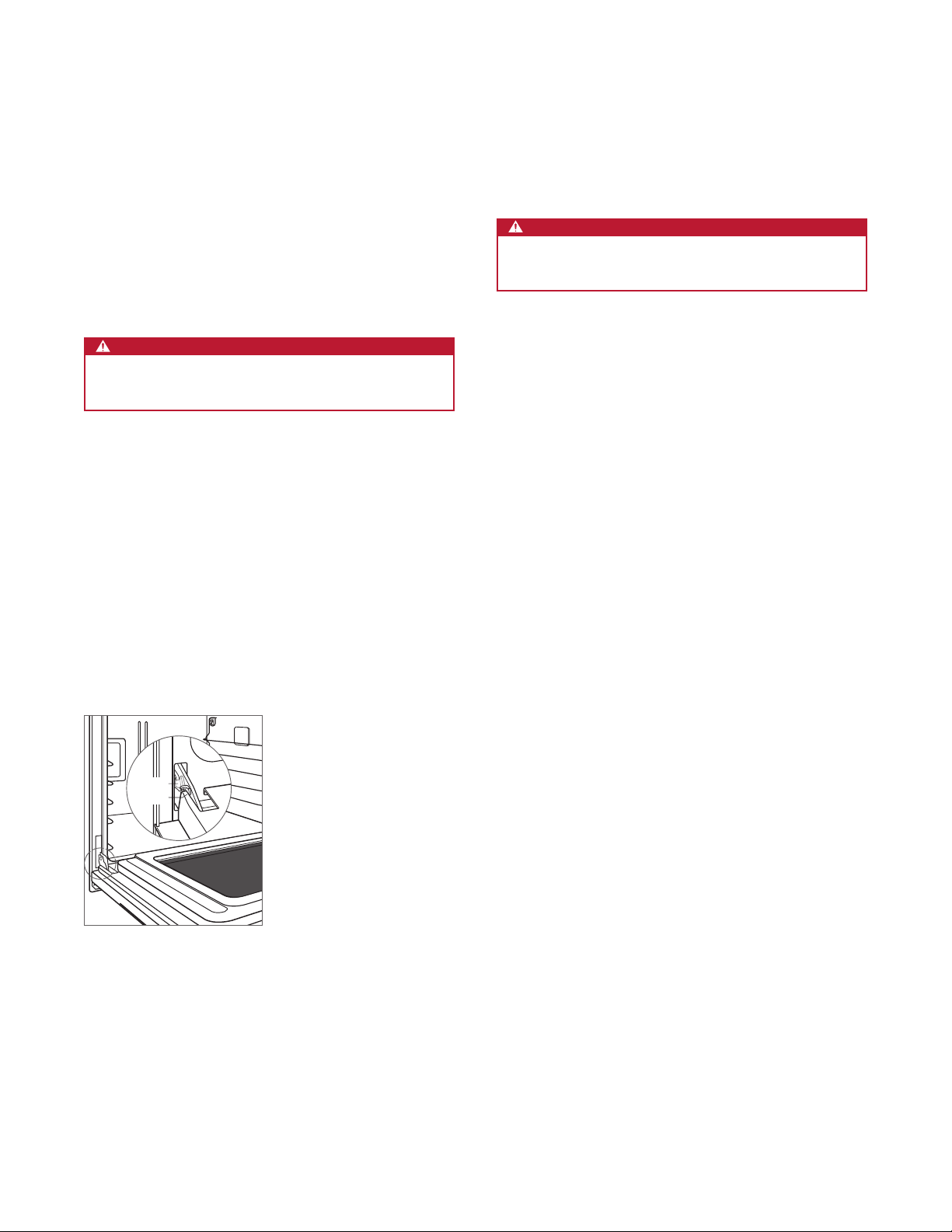
To remove, open the oven door completely. Rotate both
hinge latches forward to the open position, then lift the door
up and out. Refer to the illustration below.
To reinstall, insert the door hinges into the frame openings,
then rotate the hinge latches to the closed position.
INSTALLATION
Electrical Connection
WARNING
Verify power is disconnected from the electrical box
before proceeding.
With the oven positioned directly in front of the opening,
feed the conduit through the opening in the cabinet platform
(if applicable). Depending on local codes, connect the oven
to the electrical supply following these steps for a three-wire
or four-wire system:
1Connect the black appliance wire to the black (L1) power
supply wire in the electrical box.
2Connect the red appliance wire to the red (L2) power
supply wire in the electrical box.
3Connect the ground appliance wire to the green/ground
house grounding wire in the electrical box.
4For a four-wire system, leave the white neutral wire in the
house electrical box unconnected. Seal with a wire cap.
CLOSED
OPEN
Oven door removal

Troubleshooting
IMPORTANT NOTE: If the oven does not operate properly,
follow these troubleshooting steps:
•Verify electrical power is supplied to the oven.
•Verify proper electrical connections.
•If the oven does not operate properly, contact Wolf
Factory Certied Service. Do not attempt to repair the
oven. Wolf is not responsible for service required to
correct a faulty installation.
INSTALLATION
Installation
Place the oven in the opening and slide back. Verify the
conduit slides through the opening of the base support
and is not trapped between the oven and cabinet wall. The
conduit must t into the recessed area along the right rear
edge of the oven.
Locate the mounting holes on the oven side trim, two on
each side for a single oven and three on each side for
a double oven. Drill 1/16" pilot holes. Use the provided
mounting screws to secure the oven to cabinetry. Refer to
the illustration below.
CAUTION
Failure to install the mounting screws may cause the
oven to tip forward during use.
CAUTION
For proper ventilation, do not block the exhaust vent
located at the bottom of the oven.
CONTROL PANEL ALIGNMENT
To adjust alignment, open the oven door and loosen the
two screws under the control panel. Pivot the bottom of the
control panel in or out, then tighten the screws. Refer to the
illustration below.
wolfappliance.com
|
11
SCREWS
Mounting holes
Control panel alignment
MOUNTING
HOLES
Sub-Zero, Sub-Zero & Design, Sub-Zero & Snowake Design, Dual Refrigeration, The Living Kitchen, Great American Kitchens The Fine Art of Kitchen Design, Wolf, Wolf &
Design, Wolf Gourmet, W & Design, red colored knobs, Cove, and Cove & Design are registered trademarks and service marks of Sub-Zero Group, Inc. and its subsidiaries.
All other trademarks are property of their respective owners in the United States and other countries.

2
|
Atención al cliente de Wolf 800.222.7820
HORNO DE LA SERIE E
Contenido
3Horno de la serie E
4Especicaciones
10 Instalación
11 Resolución de problemas
Las características y especicaciones están sujetas a
cambios sin previo aviso. Visite wolfappliance.com/specs
para obtener la información más actualizada.
Aviso importante
Para garantizar que este producto se instale y opere de
la forma más segura y eciente posible, tome nota de los
siguientes tipos de información resaltada en esta guía:
AVISO IMPORTANTE señala la información que es
especialmente importante.
PRECAUCIÓN indica una situación en la que se pueden
sufrir heridas leves o provocar daños al producto si no se
siguen las instrucciones.
ADVERTENCIA indica peligro de que se produzcan heridas
graves o incluso la muerte si no se siguen las precauciones.
AVISO IMPORTANTE: En toda esta guía, las dimensiones
entre paréntesis son milímetros, a menos que se especique
lo contrario.
AVISO IMPORTANTE: Guarde estas instrucciones para el
inspector eléctrico local.

wolfappliance.com
|
3
HORNO DE LA SERIE E
Información del producto
La información importante del producto, incluido el modelo
y número de serie de la unidad, se encuentra en la placa de
datos del producto. La placa de datos se encuentra debajo
del panel de control. La puerta del horno debe estar abierta
para ver la placa de datos. Consulte la siguiente ilustración.
Si necesita servicio, póngase en contacto con el centro de
servicio autorizado de Wolf y tenga a la mano el modelo y
número de serie de la unidad. Para obtener los datos del
centro de servicio autorizado de Wolf más cercano o si
tiene preguntas acerca de la instalación, visite la sección de
contacto y soporte técnico en nuestra página de Internet
wolfappliance.com o llame a la línea de atención al cliente
de Wolf al 800-222-7820.
Ubicación de la placa de datos
PLACA DE
DATOS

4
|
Atención al cliente de Wolf 800.222.7820
ESPECIFICACIONES
INSTALACIONES COMBINADAS
Los hornos empotrados de Wolf están diseñados y
cuentan con aprobación de la agencia para instalarlos
únicamente con las estufas, hornos de microondas y
cajones calentadores de Wolf. El ancho nominal del horno
debe coincidir con el ancho nominal de la estufa. Un horno
empotrado no puede ser instalado debajo de una estufa
Wolf.
Para conocer las instalaciones combinadas típicas, consulte
la Guía de diseño Wolf.
El horno sencillo se puede instalar al lado de otro horno
sencillo de la serie E. Debe dejar un espacio de 11/2"
(38) entre las aberturas de los hornos. Para cada horno
se necesita una pared interna independiente entre las
aberturas.
Requisitos de instalación
El horno se puede instalar en una aplicación estándar o
empotrable. Es posible que la ubicación del suministro
eléctrico al interior de la abertura del horno requiera de un
gabinete de mayor profundidad.
Dé el acabado a los bordes de la abertura. Pueden ser
visibles cuando la puerta está abierta.
Para las instalaciones empotrables se requiere un margen
mínimo de 1/4"(6) en todos los lados. Para asegurarse de
tener un margen uniforme de 1/4"(6), cada esquina de la
abertura debe tener exactamente 90°.
REQUISITOS DE INSTALACIÓN
SOPORTE DE LA BASE MIN
Horno sencillo 250 lb (115 kg)
Horno doble 400 lb (181 kg)
RIBETE (INSTALACIÓN ESTÁNDAR)
Superposición superior 1/2"(13)
Superposición inferior 1/8"(3)
Superposición lateral 11/16"(17)

wolfappliance.com
|
5
ESPECIFICACIONES
Instalación eléctrica
La instalación debe cumplir con todos los códigos eléctricos
vigentes. Coloque el suministro eléctrico a ras con la pared
posterior y dentro del área sombreada que se muestra en
la ilustración de las páginas siguientes para su instalación
especíca. Para facilitar la instalación, el suministro eléctrico
para el horno se puede colocar en un gabinete adyacente
al alcance del conducto. Utilice únicamente el conducto
suministrado con este electrodoméstico.
El rendimiento puede verse comprometido si el suministro
eléctrico es menor a 240 voltios.
El diagrama de cableado que abarca el circuito de control
viene con el horno.
REQUISITOS ELÉCTRICOS—HORNO SENCILLO
Suministro eléctrico Con conexión a tierra, 240/208 V CA,
60 Hz
Servicio Circuito dedicado de 30 amperes
Total de amperes 21
Carga máxima conectada 5.1 kW
REQUISITOS ELÉCTRICOS—HORNO DOBLE
Suministro eléctrico Con conexión a tierra, 240/208 V CA,
60 Hz
Servicio Circuito dedicado de 50 amperes
Total de amperes 37
Carga máxima conectada 8.9 kW
ADVERTENCIA
Todo el electrodoméstico debe estar conectado a tierra
correctamente en todo momento cuando se suministre
energía eléctrica.
Está prohibido realizar la conexión a tierra a través
del conductor neutro para las nuevas instalaciones de
circuito derivado (1996 NEC), casas rodantes y vehículos
recreativos, o donde los códigos locales prohíban la
conexión a tierra a través del conductor neutro.
Si se utiliza cableado de aluminio para el suministro
de una casa, empalme el cable de cobre del
electrodoméstico con el cableado de aluminio de
la casa con conectores de diseño especial y con
certicación de la agencia para unir cobre y aluminio.
Siga cuidadosamente el procedimiento recomendado
por el fabricante del conector. Una conexión incorrecta
puede producir un incendio.
Ubicación de la placa de datos
PLACA DE
DATOS

6
|
Atención al cliente de Wolf 800.222.7820
ESPECIFICACIONES
Horno sencillo de la serie E
INSTALACIÓN ESTÁNDAR
E
E
E
VISTA FRONTAL
VIST
A LATERAL
NOTA: Es posible que la ubicación del suministro eléctrico al interior de la abertura requiera
de un gabinete de mayor profundidad. La línea punteada representa el perfil de la unidad.
5"
(127)
4"
(102)
271/4"
(692)
ALTURA DE
LA ABERTURA
24" (610)
PROFUNDIDAD
DE LA ABERTURA
281/2" (724)
ANCHURA
DE ABERTURA
VISTA SUPERIOR

wolfappliance.com
|
7
ESPECIFICACIONES
E
E
E
VISTA FRONTAL
VIST
A LATERAL
NOTA: Es posible que la ubicación del suministro eléctrico al interior de la abertura requiera
de un gabinete de mayor profundidad. La línea punteada representa el perfil de la unidad.
493/4"
(1264)
ALTURA DE
LA ABERTURA
5"
(127)
4"
(102)
24" (610)
PROFUNDIDAD
DE LA ABERTURA
281/2" (724)
ANCHURA DE
ABERTURA
17" (432)
TÍPICA
VISTA SUPERIOR
Horno doble de la serie E
INSTALACIÓN ESTÁNDAR

8
|
Atención al cliente de Wolf 800.222.7820
ESPECIFICACIONES
E
E
E
VISTA FRONTAL
VIST
A LATERAL
*Las áreas sombreadas serán visibles y se les debe dar un acabado que combine con los gabinetes
.
**1" (25) para modelos profesionales y de transición y 11/4" (32) para el modelo contemporáneo.
NOTA: Es posible que la ubicación del suministro eléctrico al interior de la abertura requiera
de un gabinete de mayor profundidad. La línea punteada representa el perfil de la unidad
.
283/8"
(721)
ALTURA
EMPOTRABLE
3/4"(19)
3/8" (10)
15/16" (24)
5"
(127)
4"
(102)
25" (635)
PROFUNDIDAD DE
LA INSTALACIÓN
EMPOTRABLE
CORNAMUSAS
TERMINADAS*
303/8" (772)
ANCHO DE
LA INSTALACIÓN EMPOTRABLE
1" (25)
O
11/4" (32)**
VISTA SUPERIOR
Horno sencillo de la serie E
INSTALACIÓN EMPOTRABLE

wolfappliance.com
|
9
ESPECIFICACIONES
Horno doble de la serie E
INSTALACIÓN EMPOTRABLE
E
E
E
VISTA FRONTAL
VIST
A LATERAL
*Las áreas sombreadas serán visibles y se les debe dar un acabado que combine con los gabinetes
.
**1" (25) para modelos profesionales y de transición y 11/4" (32) para el modelo contemporáneo.
NOTA: Es posible que la ubicación del suministro eléctrico al interior de la abertura requiera
de un gabinete de mayor profundidad. La línea punteada representa el perfil de la unidad
.
507/8"
(1292)
ALTURA
EMPOTRABLE
17" (432)
TÍPICA
3/4"(19)
3/8" (10)
15/16" (24)
5"
(127)
4"
(102)
25" (635)
PROFUNDIDAD DE
LA INSTALACIÓN
EMPOTRABLE
CORNAMUSAS
TERMINADAS*
303/8" (772)
ANCHO DE
LA INSTALACIÓN EMPOTRABLE
1" (25)
O
11/4" (32)**
VISTA SUPERIOR

10
|
Atención al cliente de Wolf 800.222.7820
Preparación
Antes de mover el horno, proteja cualquier suelo acabado y
asegúrese de que la puerta del horno esté cerrada para que
no se dañe.
Utilice una plataforma rodante para mover la unidad cerca
de la abertura. Retire y recicle los materiales de embalaje.
No utilice la manija de la puerta del horno para levantarlo ni
transportarlo.
PRECAUCIÓN
No utilice la manija de la puerta del horno para levantarlo.
Esto puede dañar la puerta del horno y las bisagras.
CÓMO QUITAR LA PUERTA DEL HORNO
Puede quitar la(s) puerta(s) del horno para aligerar la carga
o para pasar el horno por una puerta. Quítela únicamente
si es necesario. El proceso para quitar la puerta del horno
solamente debe ser realizado por un instalador certicado o
un técnico de servicio.
Para quitarla, abra la puerta completamente. Gire los
pestillos de las dos bisagras hacia adelante a la posición
abierta y, a continuación, levante la puerta hacia arriba y
hacia fuera. Consulte la siguiente ilustración.
Para reinstalarla, inserte las bisagras de la puerta en las
aberturas del marco y gire los pestillos de las bisagras hacia
la posición de cerrado.
INSTALACIÓN
Conexión eléctrica
ADVERTENCIA
Verique que la alimentación esté desconectada de la
caja eléctrica antes de proceder.
Con el horno situado directamente frente a la abertura,
pase el conducto por la abertura que se encuentra en la
plataforma del gabinete (en su caso). Dependiendo de los
códigos locales, conecte el horno al suministro eléctrico
siguiendo estos pasos para un sistema de tres hilos o de
cuatro hilos:
1Conecte el cable negro del electrodoméstico al cable
negro (L1) del suministro eléctrico en la caja eléctrica.
2Conecte el cable rojo del electrodoméstico con el cable
rojo (L2) del suministro eléctrico en la caja eléctrica.
3Conecte el cable de conexión a tierra del
electrodoméstico al cable verde/de conexión a tierra
de la casa en la caja eléctrica.
4Para un sistema de cuatro hilos, deje desconectado el
cable blanco neutro en la caja eléctrica de la casa. Selle
con una cubierta protectora.
ABIERTO
CERRADO
Cómo quitar la puerta del horno
This manual suits for next models
4
Table of contents
Languages:
Other Wolf Oven manuals

Wolf
Wolf e Series User manual

Wolf
Wolf M Series User manual

Wolf
Wolf e Series User manual

Wolf
Wolf CSO24 User manual

Wolf
Wolf DO30F User manual

Wolf
Wolf DO30F Instructions for use

Wolf
Wolf DO30U/B User manual

Wolf
Wolf M Series User manual

Wolf
Wolf E Series User manual

Wolf
Wolf CONVECTION STEAM OVENS User manual