Wolfgang Warmbier 7100.CPM74 User manual

User's Manual Charged Plate Monitor
Part No. 7100.CPM74
_
Page 1 of 10 V0508
Wolfgang Warmbier GmbH & Co. KG
Untere Gießwiesen 21
D-78247 Hilzingen/Germany
www.warmbier.com
User's Manual
Charged Plate Monitor
7100.CPM74

User's Manual Charged Plate Monitor
Part No. 7100.CPM74
_
Page 2 of 10 V0508
1. Description
The Charged Plate Monitor CPM74 consists of an integrated timer, a high-voltage unit and a
rotating chopper field mill sensor and achieves therefore the 1016 high impedance required
for measuring electrostatic voltage potentials and static decay times of air ionizers.
The instrument complies with DIN EN 61340-5-1 and ANSI/ESD STM3.1.
152mm
For the vertical measurement use the included three Distance pieces.
Screw them on the backside of the unit.
Important: The high voltage unit is protected by a high ohmic current limiting resistor and
therefore there is no danger when touching the charged plate.
The CPM74 is battery powered and due to its compact design, it is very suitable for the
mobile use in industrial areas. It can also be operated at a power supply.
The CPM74 is menu-driven and will be controlled by means of 2 switches for simple
operation. All selected parameters will be shown in the 2 rows LCD-display for a better
orientation for the operator.
1.1 Technical Data
Dimensions (L x B x H):
152mm x 152mm x 152mm
Weight:
app. 1,5kg
Display:
Alphanumeric display (100mm x 24mm)
2 lines with 16 characters
Ranges:
Charge Plate: Charge ±1000V
Voltmeter (MK11): Voltage ±2000V
Voltmeter (Plate): Voltage ±4000V
Output:
Analog ± 1V
Battery:
7,2V / 1300mAh
Battery lifetime:
Last approximately 4 hours for continuous operation when
battery was fully charged
Charging time:
Max. 14h
Power supply:
230V / 50Hz / 12V DC / 750mA
Load Current:
Max. 600mA, max. 150mA for battery operation
Operating temperature:
0…40°C
Relative Humidity:
10…60%

User's Manual Charged Plate Monitor
Part No. 7100.CPM74
_
Page 3 of 10 V0508
1.2 Overview
1
Plate electrode
8
Handle
2
LCD-Display
9
Power supply 12V
3
Button «A»
10
Serial interface
4
Protection cap
11
Analogue output
5
Electrofield-Sensor
12
Ground socket
6
Button «B»
13
Earth socket
7
Distance support bushing
1
2
3
4
5
6
7
8
9
10
11
12
13

User's Manual Charged Plate Monitor
Part No. 7100.CPM74
_
Page 4 of 10 V0508
2. Operation
The Charged Plate Monitor CPM 74 is equipped with a NiCd-battery and ready for
operation - use the enclosed power supply only to charge the battery. The display
background illumination is off when battery powered. The battery operation features an
automatic switch-off function, if the switches were not pressed for approximately 10
minutes.
3. Mode
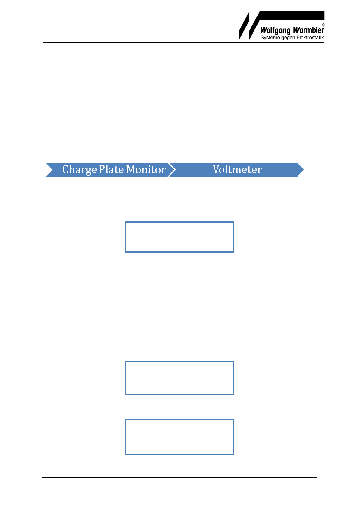
The CPM 74 can be operated in Charged Plate Monitor Mode or Voltmeter Mode.
Button «B» toggles between the two modes.
4. Charged Plate Mode
4.1 Decay Time and Offset Voltage
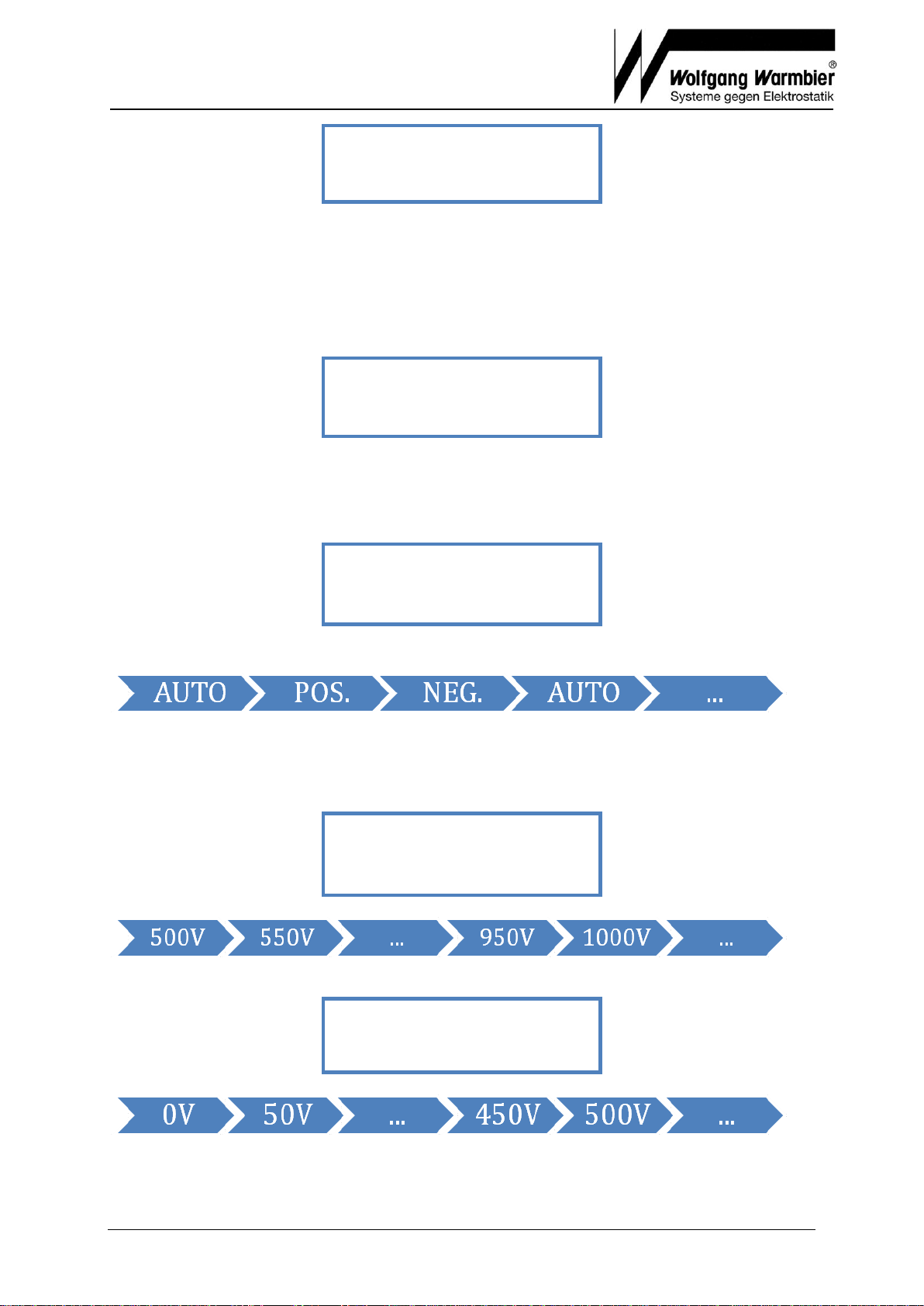
The selected mode and request to start a measurement is displayed:
The initially setting is saved and will be shown after each switch-on.
If the auto-mode is selected, as indicated in the example above, then the time will be
measured for the positive voltage decay first, and then followed automatically for the
negative voltage. This mode is recommended for checking air ionizer equipment, as the
Start-button has to be pushed only once to perform a complete check of an ionizer.
Offset-Voltage is the voltage potential, which remains after a certain time on the plate
electrode. It is an indication for the balance of positive and negative ions. If the Offset-
Voltage is positive, an excess of positive ions emanate from the ionizer equipment - the
other way round for negative. Please consider the specification of the ionizer for a
qualified evaluation.
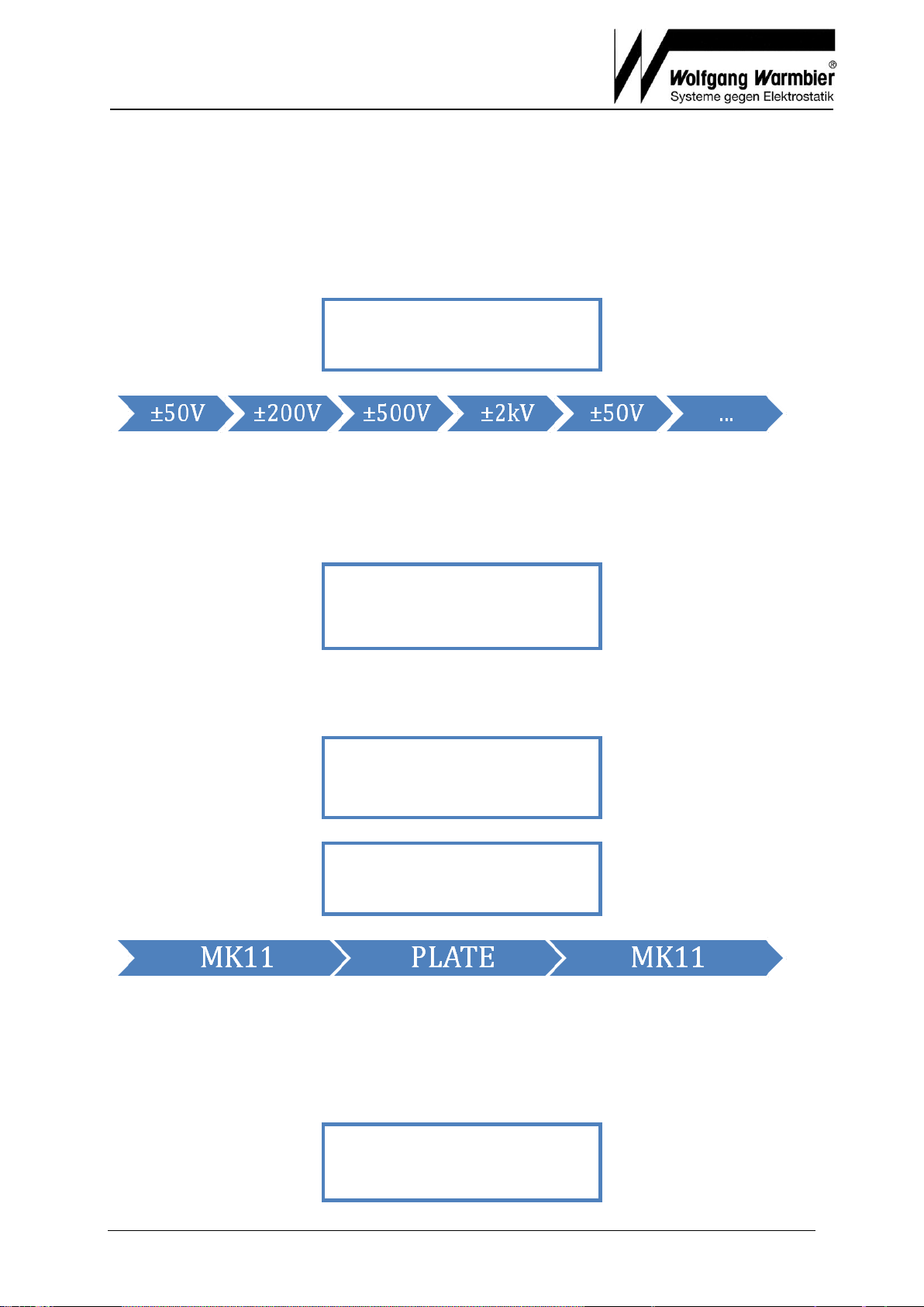
Press Button «A» to start the measurement. The plate-electrode will be charged.
The timer starts when the voltage on the plate falls below the upper threshold (1000 volt
in this case).
It will stop when it reaches the lower threshold (example: 100 volt). The values can be
changed in the Setup.
TIMER = XX.Xs
U = XXXXV
TIMER: 1000-100V
U > 1200V
DECAY TIME: AUTO
PRESS START !

User's Manual Charged Plate Monitor
Part No. 7100.CPM74
_
Page 5 of 10 V0508
Note: The minimum resolution is 0,1 second. A lower values is
displayed as <0,1s
The offset-voltage will be measured after a certain lapse time at the end of the static decay
time measurement.
The measurement series is now finished and all relevant values are indicated on the display.
The offset-voltage UOFF and the relating time is displayed in the first row. The decay time is
in the second row. POS.DECAY, NEG.DECAY or both alternate in auto mode.
Press button «A» to continue.
4.2 Saving measurement values
The measured values can be saved in the internal memory after each measurement by
pressing Button «A».
99 memory locations are available. Memory full is indicated when no space is left.
Press button «A» to delete the entire memory. To skip without saving press button «B»
4.2.1 Select memory location
The next free memory location is suggested.
Press «A» to accept this memory location.
Press «B» to change the location.
PLEASE WAIT !
SAVING !
FILE NO: XX
A<YES CHANGE>B
DELETE FILES?
A<YES NO>B
MEMORY FULL!
SAVE VALUES?
A<YES NO>B
OFF = XXXV T = XXXs
POS.DECAY = XX.Xs
OFFSET = XXXs
U = XXXXV

User's Manual Charged Plate Monitor
Part No. 7100.CPM74
_
Page 6 of 10 V0508
Press button «A» or «B» to decrement the file number.
Important: Only existing memory locations can be overwritten.
After 3 seconds the display switches back and the values can be stored to the indicated
location by pressing button «A».
4.3 Configuration
Press button «A» and «B» simultaneously to enter the set-up function.
Pressing button «A» will start the SETUP. Button «B» switches to the ZERO ADJUST menu.
4.3.1 Set-up
The current settings will appear.
Select the mode with button «B», accept the displayed mode with button «A».
Available modes are POSITIVE, NEGATIVE and AUTO. Auto mode measures positive and
negative in sequence.
Select the start threshold voltage:
Button «A» accepts the displayed voltage, button «B» changes the value to:
Select the stop threshold voltage:
Button «A» accepts the displayed voltage, button «B» changes the value to:
Select the time decay for the offset voltage:
STOP: U = 100V
A<OK CHANGE>B
START: U = 1000V
A<OK CHANGE>B
MODE = AUTO
A<OK CHANGE>B
SET-UP ?
A<YES NO>B
FILE NO: XX
A<-10 -1>B

User's Manual Charged Plate Monitor
Part No. 7100.CPM74
_
Page 7 of 10 V0508
Button «A» accepts the displayed time, button «B» changes the value to:
The selected values are displayed for 3 seconds,
and finally need to be confirmed.
Press Button «A» to accept the settings. Press «B» to revise.
Confirm to clear the memory:
Important: After changing set-up parameters the memory must be cleared because the
stored data relates to those parameters.
Press button «A» to clear.
Button «B» will skip all changes.
4.3.2 Zero Adjust
The Zero adjust menu is displayed when selecting NO in the Set-up (button «B»).
Pressing button «A» will set the offset to zero.
Button «B» skips this function.
Important: Make sure the plate electrode voltage is zero at this time.
PLEASE WAIT!
CALIBRATION!
ZERO ADJUST?
A<YES NO>B
PARAMETER
NOT CHANGED !
PARAMETER
CHANGED
CLEAR MEMORY?
A<YES NO>B
TIMER + OFFSET OK?
A<YES NO>B
TIMER: 1000-100V
OFFSET: 1 min
OFFSET: 10s
A<OK CHANGE>B

User's Manual Charged Plate Monitor
Part No. 7100.CPM74
_
Page 8 of 10 V0508
5. Voltmeter Mode
5.1 Measuring Voltage
Measuring the voltage can be achieved either by using the plate or by disassembling the
plate and using the high voltage head MK11.
5.2 Range Adjustment
See paragraph Mode how to switch to Voltmeter mode.
Pressing button «A» selects the range as shown below for high voltage head MK11:
The range is displayed in the upper right (2kV in our example).
In plate mode the values are double ±100V, ±400V, ±1kV and ±4kV!
PLATE instead of MK11 is indicated in the lower left corner in this case.
5.3 Configuration
Press button «A» and «B» simultaneously to enter the set-up function.
Pressing button «A» will start the SETUP. Button «B» switches to the ZERO ADJUST menu.
5.3.1 Changing the Mode
Confirm to change the mode.
Press button «A» to change.
Toggle the mode with button «B».
MK11: High voltage head
PLATE: Plate electrode
5.3.2 Zero Adjust
The Zero adjust menu is displayed when selecting NO in the Set-up (button «B»).
Pressing button «A» will check the mode.
ZERO ADJUST ?
A<YES NO>B
V-MODE: MK11!
A<OK CHANGE>B
SELECT MODE?
A<YES NO>B
SET_UP ?
A<YES NO>B
V-METER ±2kV
MK11! 0,00kV

User's Manual Charged Plate Monitor
Part No. 7100.CPM74
_
Page 9 of 10 V0508
In MK11 mode you must confirm that the high voltage head MK11 is mounted properly.
In PLATE mode you must confirm the plate is mounted properly.
In MK11 mode the high voltage head must be grounded for zero adjust.
In PLATE mode the plate voltage must be zero. You might ground the plate to assure this.
The zero adjust starts after confirming with button «A».
Important: No foreign voltage must be appied to the unit or the plate electrode during
calibration. Calibration without high voltage head can be performed by using the supplied
protection cap. Put on the cap and confirm zero adjust with grounded MK11.
6. Additional Messages
If the electrofield-meter is defect, the following message will appear:
If the power of the NiCd Battery is less than 6,7 volts, the unit will provide the following
message alternating every second with the actual first row:
The battery has to be recharged, but the ongoing or the upcoming measurement could be
finished first.
Important: Only use the supplied power supply. The battery will be charged if the unit is
switched off. The maximum charge time is 14 hours.
If the battery voltage will become less than 6,4 volts, the following message will appear for
approximately 2 seconds:
and the unit will switch off automatically to prevent a total discharge of the battery. A total
discharge can cause damage or destroy the battery!
AUTO OFF
LOW BATTERY !
LOW BATTERY !
EFM DEFECT !
REPAIR IS NEEDED
PLEASE WAIT !
CALIBRATION !
PLATE FREE ?
A<YES NO>B
GROUND MK11 ?
A<YES NO>B
MK11 FIXED ?
A<YES NO>B
MK11 FIXED ?
A<YES NO>B

User's Manual Charged Plate Monitor
Part No. 7100.CPM74
_
Page 10 of 10 V0508
7. Warranty
We provide 12 month limited warranty from date of receiving the unit, if the unit was
handled properly. The damage of the NiCd-battery caused by improper handling as well
as mechanical damage on the unit are excluded from warranty. Warranty is not provided,
if the housing was opened.
Warranty void if the unit was opened!
8. Grounding
The unit has to be grounded sufficiently for accurate measurements of the electrical field
and its polarity. Therefore the unit has to be connected to ground potential by means of
its grounding socket.
9. Safety Advice
The measurement unit is not approved for the use in explosive areas!
The unit is not approved for the use in power utilities!
This unit is not suitable to measure alternating fields with a frequency higher
than 1 Hz.
Sparking discharge to the electro-fieldmill-sensor has to be avoided.
Do not charge the batteries longer than 14 hours.
10. Maintenance
The Teflon-supports of the plate electrode must be maintained clean, therefore do not touch
with fingers. All Teflon spacers and the Teflon insulated wire to the plate have to be cleaned
carefully with Acetone or similar solvents in case that the voltage on the charged plate drops
in a rate of greater than 100V / minute under normal circumstances (no external lead
connection to the plate electrode and no presence of air ionizers).
Recommended calibration interval is 2 years.
11. Important Notice
Please note the following advice when checking air ionizers:
The presence of charged objects as well as charged personnel could give erroneous test
results caused by induction. The unit should always be grounded.
Table of contents
Other Wolfgang Warmbier Measuring Instrument manuals