WOLONG WL-1.5KS User manual

Wolong Solar Inverter
Wolong Solar Omvormer
Wolong Solar Wechselrichter
Installation and operation instructions
Installatie- en bedieningshandleiding
Installation und Bedienung
EN
DE
NL


1
ENGLISH 1
NEDERLANDS 49
DEUTSCH 96

2
Table of Contents
1ABOUT THIS MANUAL.................................................................................................................... 4
1.1 GENERAL INFORMATION.......................................................................................................................4
1.2 STANDARDS AND CERTIFICATES ..............................................................................................................4
2SAFETY INSTRUCTIONS .................................................................................................................. 5
2.1 LIABILITY............................................................................................................................................5
2.2 ACCIDENT PREVENTION........................................................................................................................5
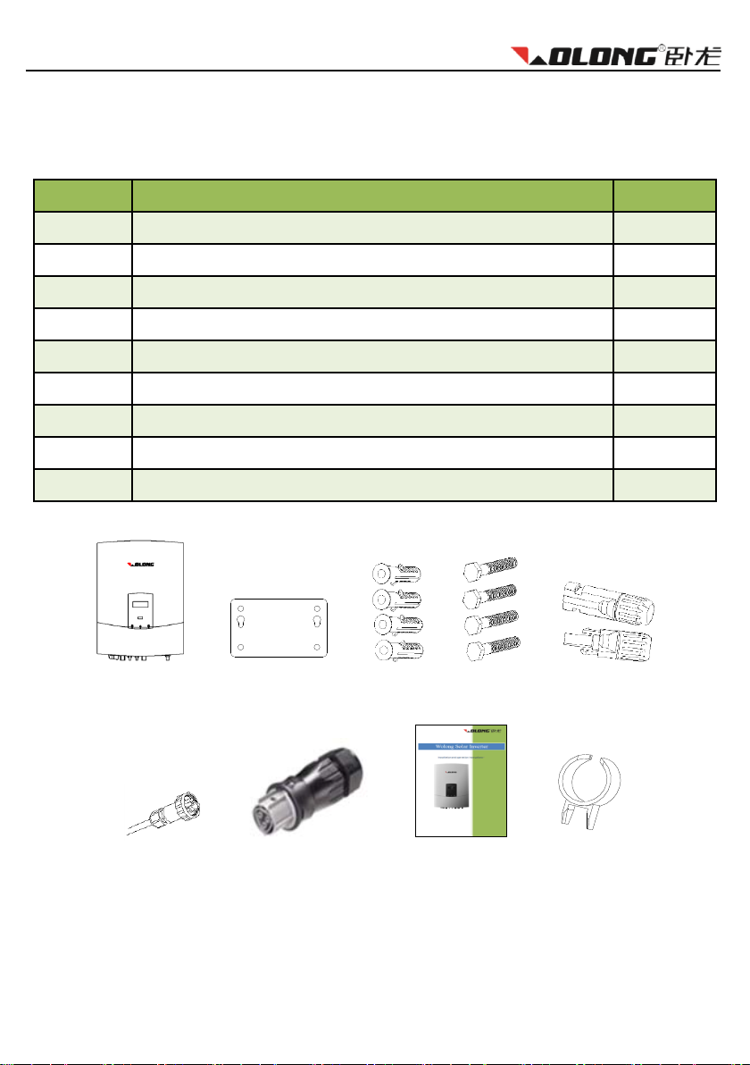
3UNPACKING.................................................................................................................................... 6
3.1 CHECKLIST..........................................................................................................................................6
3.2 CHECK FOR TRANSPORT DAMAGE ..........................................................................................................7
4TECHNICAL DATA ........................................................................................................................... 8
4.1 DC INPUT DATA...................................................................................................................................8
4.2 OUTPUT DATA.....................................................................................................................................9
4.3 EFFICIENCY AND SAFETY EQUIPMENT....................................................................................................10
4.4 GENERAL DATA..................................................................................................................................11
5INSTALLATION AND STARTUP ..................................................................................................... 12
5.1 SELECTING AN APPROPRIATE PLACE FOR INSTALLATION ............................................................................12
5.2 INSTALLING THE INVERTER...................................................................................................................15
5.3 ELECTRICAL CONNECTION ...................................................................................................................16
5.4 STARTUP ..........................................................................................................................................23
5.5 COMMUNICATION.............................................................................................................................24
5.6 SAFETY ............................................................................................................................................27
6OPERATING................................................................................................................................... 28
6.1 FRONT PANEL ...................................................................................................................................28
6.2 LED DISPLAY.....................................................................................................................................28
6.3 LCD DISPLAY ....................................................................................................................................29
6.4 FUNCTION KEY ..................................................................................................................................30
7ALARM CODES AND SOLUTIONS ................................................................................................. 32

3
8WI-FI INSTALLATION .................................................................................................................... 34
8.1 INTRODUCTION.................................................................................................................................34
8.2 INSTALLING THE WI-FI MODULE ..........................................................................................................34
8.3 REGISTERING YOUR PV SYSTEM...........................................................................................................41
8.4 THE SOLARMAN APP........................................................................................................................45
8.5 PROBLEM SOLVING ............................................................................................................................46
9SERVICE AND MAINTENANCE...................................................................................................... 47
10 RECYCLING AND DISPOSAL ...................................................................................................... 47
11 CONTACT................................................................................................................................... 48
© 2014 ATB Motors ALL RIGHTS RESERVED.
This user manual and the products described therein are protected by copyright. Under this copyright no part of this
manual may be copied, reproduced or published without the express consent of ATB Motors BV or their supplier,
except to make backups and/or to ensure normal implementation of the product. Subject to errors and/or technical
modifications. Version 1.9.2014

About this manual
4
1About this manual
Thank you for choosing the Wolong solar inverter!
The transformerless solar inverter converts the direct current (DC) generated by your solar panels into alternating
current (AC) that can be connected directly to the mains. The energy generated is fed back into the grid. When you
choose for a Wolong inverter, you choose for reliable and advanced technology.
1.1 General information
This manual refers to Wolong New Energy single phase inverters of WL-1.5KS, WL-2.0KS, WL-3.0KSS,
WL-3.0KS, WL-4.0KS, WL-4.6KS, and WL-5.0KS.
This manual contains important information regarding assembly, installation, startup and operation of the
inverters. Make sure that the instructions are read carefully.
The inverters must be installed and put into operation by qualified electricians.
Please keep all available documentation together with the inverter, so you can refer to it at any time.
1.2 Standards and certificates
Type
Normative reference
WL-1.5KS
AS3100.AS4777.EMC.IP65
IEC 62109-1 and IEC 62109-2
VDE 0126-1-1
EN50438
G83/1, G59/2
CGC
WL-2.0KS
WL-3.0KSS
WL-3.0KS
WL-4.0KS
WL-4.6KS
WL-5.0KS

Safety instructions
5
2Safety instructions
For the proper operation, please read the manual carefully before installing and operating the Wolong inverter. The
installation must comply with local regulations and technical specifications.
2.1 Liability
The inverters are designed according to the European safety regulations. However, improper use, alteration,
careless maintenance can be life threatening and cause damage to people, property and others. Wolong New
Energy is not responsible for property damage, personal injury or disability that result from unauthorized use or
negligence.
2.2 Accident prevention
Only qualified electricians who have read and fully understood all the documentation, can install, maintain
and repair the inverter.
The Wolong inverter must only be operated with a PV generator. Do not connect any other source of
energy to theWolong inverter.
Make sure that the PV generator and inverter is earthed in order to protect properties and persons.
Before opening the housing, the Wolong inverter must be disconnected from the grid and PV generator.
Wait at least five minutes after disconnecting from the power source, so the energy storage in the
capacitors is fullydischarged.

Unpacking
6
3Unpacking
3.1 Checklist
Object
Description
Quantity
A
Wolong inverter
1 pcs
B
Rear mounting panel
1 pcs
C
Expansion bolt
4 pcs
D
Screw M8x70
4 pcs
E
MC4 connectors ( including male and female side connectors )
2 pairs
F
RJ45 male connector
2 pcs
G
AC female connector
1 pcs
H
Installation and operation instructions (English / Dutch / German)
1 pcs
I
MC4 open tool
1 pcs
Please check carefully if all the components are in the carton. If something is missing, contact your dealer.
A
B
C
D
E
F
G
H
I

Unpacking
7
3.2 Check for transport damage
Thoroughly inspect the inverter during delivery, if you detect any damage to the packaging which indicates that the
inverter may be damaged, inform the responsible transport company immediately. We can provide you assistance if
required.
To prevent damage, the screen is covered by a screen shield which you can remove by yourself.

Technical data
8
4Technical data
4.1 DC input data
Type
WL-1.5KS
WL-2.0KS
WL-3.0KSS
Max. PV-generator power [W]
1800
2300
3100
Max. DC Voltage [V]
450
485
485
MPPT voltage range [V]
125-400
125 - 450
125-450
Startup voltage [V]
125
125
125
Turn off DC Voltage [V]
90
90
90
Max. DC current [A]
15
15
15
Numbers of DC connection
1
2
2
Number of MPP trackers
1
1
1
DC connector
MC4 or H4
Turn on power [W]
10
Type
WL-3.0KS
WL-4.0KS
WL-4.6KS
WL-5.0KS
Max. PV-generator power [W]
3500
4300
4600
5300
Max. DC Voltage [V]
550
550
550
550
MPPT voltage range [V]
125 - 530
125 - 530
125-530
125 - 530
Turn off DC Voltage [V]
125
125
125
125
Max. DC current [A]
20
20
20
20
Nominal DC current [A]
18
18
18
18
Numbers of DC connection
1/2
1/2
1/2
2
Number of MPP trackers
2
2
2
2
DC connector
MC4 or H4
Turn on power [W]
10

Technical data
9
4.2 Output data
Type
WL-1.5KS
WL-2.0KS
WL-3.0KSS
AC connector
Plug-in connector
Power connection
Single phase
Rated AC power [W]
1500
2000
3000
Max. AC Power [W]
1650
2200
3000
Grid voltage range [V]
Comply with AS4777, VDE 0126-1-1, EN50438, G83/1, G59/2,
CGC
Grid frequency range [Hz]
Comply with AS4777, VDE 0126-1-1, EN50438, G83/1, G59/2,
CGC
Rated current [A]
6.8
9.1
13.7
Max. current [A]
7.5
10
13.7
Power factor
0.99
0.99
0.99
Harmonic distortion (THD) at rated output
<2%
<2%
<2%
Power consumption at night [W]
<0.2
<0.2
<0.2
Power consumption at standby [W]
6
6
6
Type
WL-3.0KS
WL-4.0KS
WL-4.6KS
WL-5.0KS
AC connector
Plug-in connector
Power connection
Single phase
Rated AC power [W]
3000
3600
4000
4600
Max. AC Power [W]
3300
4000
4400
5000
Grid voltage range [V]
Comply with AS4777, VDE 0126-1-1, EN50438, G83/1, G59/2,
CGC
Grid frequency range [Hz]
Comply with AS4777, VDE 0126-1-1, EN50438, G83/1, G59/2,
CGC
Rated current [A]
13.6
16.5
18.2
20.9
Max. current [A]
15.0
18.2
20.0
23.0
Power factor
0.99
0.99
0.99
0.99
Harmonic distortion (THD) at rated output
<2%
<2%
<2%
<2%
Power consumption at night [W]
<0.2
<0.2
<0.2
<0.2
Power consumption at standby [W]
6
6
6
6

Technical data
10
4.3 Efficiency and safety equipment
Type
WL-1.5KS
WL-2.0KS
WL-3.0KSS
Efficiency
Max. efficiency
97.60%
97.60%
98.05%
Euro efficiency (at 360VDC)
96.50%
96.50%
96.50%
MPPT adaptation efficiency
99.50%
99.50%
99.50%
Safetyequipment
Internal overvoltage protection
Comply with AS4777, VDE 0126-1-1, EN50438, G83/1, G59/2, CGC
DC Insulation monitoring
Comply with AS4777, VDE 0126-1-1, EN50438, G83/1, G59/2, CGC
Earth fault protection
Comply with AS4777, VDE 0126-1-1, EN50438, G83/1, G59/2, CGC
Mains monitoring
Comply with AS4777, VDE 0126-1-1, EN50438, G83/1, G59/2, CGC
Earth fault current monitoring
Comply with AS4777, VDE 0126-1-1, EN50438, G83/1, G59/2, CGC
DC current monitoring
Comply with AS4777, VDE 0126-1-1, EN50438, G83/1, G59/2, CGC
Islanding protection
Comply with AS4777, VDE 0126-1-1, EN50438, G83/1, G59/2, CGC
Type
WL-3.0KS
WL-4.0KS
WL-4.6KS
WL-5.0KS
Efficiency
Max. efficiency
97.8%
98.05%
98.05%
98.05%
Euro efficiency (at 360VDC)
96.5%
97.00%
97.00%
97.00%
MPPT adaptation efficiency
99.5%
99.50%
99.50%
99.50%
Safetyequipment
Internal overvoltage protection
Comply with AS4777, VDE 0126-1-1, EN50438, G83/1, G59/2, CGC
DC Insulation monitoring
Comply with AS4777, VDE 0126-1-1, EN50438, G83/1, G59/2, CGC
Earth fault protection
Comply with AS4777, VDE 0126-1-1, EN50438, G83/1, G59/2, CGC
Mains monitoring
Comply with AS4777, VDE 0126-1-1, EN50438, G83/1, G59/2, CGC
Earth fault current monitoring
Comply with AS4777, VDE 0126-1-1, EN50438, G83/1, G59/2, CGC
DC current monitoring
Comply with AS4777, VDE 0126-1-1, EN50438, G83/1, G59/2, CGC
Islanding protection
Comply with AS4777, VDE 0126-1-1, EN50438, G83/1, G59/2, CGC

Technical data
11
4.4 General data
Type
All Wolong single phase inverters
Installation environment
indoor and outdoor
Operating temperature range
-20°C to +60°C(up to 45°C derating)
Relative humidity
0% to 98%, no condensation
Site altitude
Up to 2000 m without derating above sea level
IP protection type
IP 65 according to IEC 60529
Isolation type
Transformerless
Cooling concept
Convection
Noise level
< 40 dB
LED indication
3
LCD display
Backlight, 16×2 Character LCD
Data logger
Data communication interfaces
RS232/RS485/Wi-Fi

Installation and startup
12
5Installation and startup
5.1 Selecting an appropriate place for installation
Danger!
Danger of lethal injury due to fire or explosion!
The Wolong inverter may become hot in normal operation.
Do not install the inverter:
on easilyflammable materials
where flammable materials are stored
where there is a risk of explosion.
Caution!
Contact with the housing can cause burn injuries!
Install the Wolong inverter at a proper place where it cannot be touched
unintentionally.
Be sure that the inverter is out of children’s reach.
5.1.1 Dimensions and weight
Type
WL-1.5KS
WL-2.0KS
WL-3.0KSS
Net Weight (Kg)
13.5
13.9
14.2
Dimension L×W×D (mm)
420 x 331 x 160
Type
WL-3.0KS
WL-4.0KS
WL-4.6KS
WL-5.0KS
Net Weight (Kg)
21.3
21.3
21.3
21.3
Dimension L×W×D (mm)
520 × 365 × 175
5.1.2 Ambient conditions
1. Install the inverter on a place as dry as possible in order to extend its service life.
2. Ensure good access to the inverter for installation or any service work that may be required later.
3. Maintain the following minimum clearances around the inverter.

Installation and startup
13
Direction
Minimum clearance (cm)
One inverter
Series of inverters
above
30
30
below
30
30
right / left side
30
20
neighbouring inverters
-
40
Minimum clearances around one inverter:
Minimum clearances for series of inverters:

Installation and startup
14
4. If the wall is wooden, please add heat insulation material betweenWolong inverter and the wooden wall.
5. Do not expose the Wolong inverter to direct sunlight to avoid power reduction caused by excessive
heating. An ambient temperature below 45°C will guarantee the inverter to work in an optimal operating
state.
6. Provide adequate ventilation for the inverter to ensure that heat is dissipated.
7. If the inverters are installed in a residential area, they should be fixed on a concrete wall (a wooden wall
and plastic board are not recommended). If installed on a wooden wall, we do not recommend self-tapping
screws and wall plugs that are included with the inverter. Instead, please use the M6 bolt, nut, flat and lock
washer, each 4pcs (not included). The bolt should be 10mm longer than the thickness of the wooden
board in order to correctly fix the nut. The wooden board should be at least 15mm thick and made of a
strong wooden material to meet the strength requirements.
8. Do not put anything on the inverter.
9. Before cleaning, disconnect the Wolong inverter from the grid (by cutting off the AC breaker) and from the
PV generator (by cutting off the DC breaker) in order to exclude the danger of electric shock.Wait at least
5 minutes, then clean the unit with a soft, dry cloth. Never use corrosive, solvent-containing or abrasive
cleaners or polishes.
5.1.3 Mounting position
1. The unit has been designed for installations that require vertical or tilted backwards (by max. 15°) position.
2. Do not install the Wolong inverter tilted forwards.
3. Do not install the Wolong inverter horizontally.
4. Installing at eye level makes it easier to operate and read the display.

Installation and startup
15
5.2 Installing the inverter
Installing procedure:
The installation must comply with local regulations and technical specifications.
a) Drilling holes
Use the holes in the mounting panel to select the correct drilling position. The
space between every two holes is shown in the figure on the right. Drill four
holes at the selected installation position. Avoid tilting the holes. The depth of
the holes must be the same and within the range of 55 - 60 mm.
Attention!
Before inserting wall plugs, measure the depth of every hole and the distance
between every two holes. If the measure values do not meet the installing
requirements, re-drill holes in the wall.
b) The screws
After drilling holes in the wall, place the four wall plugs (object 2 shown in the drawing below) in the holes using a
rubber hammer. Then, screw the four self-tapping screws (object 1 shown in the drawing below) into the wall plugs.

Installation and startup
16
c) Attachment
Attach the inverter to the screws slightly tilted downwards.
5.3 Electrical connection

Installation and startup
17
Connection procedure for AC:
1. Use a multimeter to check whether the voltage and frequency of the public grid is within the
range of permissible voltage and frequency.
2. Fix a manual AC breaker between the public grid and the inverter. Keep it disconnected at all
time during connection procedure. Choose an appropriate breaker according to the AC output
specification of the inverter (rated voltage must be 230VAC or higher, and rated current 25-
32A). For each inverter installed, you must fix a separate AC breaker.
Connection procedure for DC:
1. Use a multimeter to measure the open circuit voltage of the PV strings: it must be less than the
maximum input voltage of the inverter.
2. Check the short circuit current of the PV strings on the datasheet of the PV generator: it must
be less than the maximum input current of the inverter.
3. Fix a manual DC breaker between the PV generator and the inverter. Keep it disconnected at
all time during connection procedure. Choose an appropriate breaker according to the DC
input specification of the inverter (rated voltage must 500VDC or higher, and rated current 25-
32A).
Attention!
The DC breaker should have a certain capacity of overcurrent and overvoltage.
Object
Description
1
DC-switch (option): Switch the DC-input on or off.
2
DC input: Plug-in connectors for connecting the PV modules. Their polarity is positive,
negative, negative and positive, which is marked at side of the connectors.
3
Communication connections: Wolong inverters are configured with RS485 interface.
4
AC output: plug-in connector for public grid
1
2
3
4

Installation and startup
18
Notes:
1. After the inverter has been mounted in its fixed position, the electrical
connection to the unit can be established.
2. Choose the appropriate cable model for AC wire (AWG 10, 4mm2) and for DC
wire (AWG 12, 2.5 mm2).
3. To ensure safety before the inverter is totally installed, the AC and DC end
must be disconnected from all power sources.
5.3.1 Connection to the public grid (AC)
Attention !
You must safeguard each inverter with an individual AC breaker so that the inverter
can be safely disconnected under load.
Connect AC wires with the inverter via the AC female connector. Please follow the procedures listed below:
1. Switch off the AC breaker and secure against being switched back on accidentally.
2. Strip the cable 7mm.
3. Open the AC female connector and connect the wires (three wires: L, N and PE) as shown in the figures
below. Insert the striped cable wires (L, N and PE) into the corresponding three holes of the AC female
connector. The polarity of each hole is signed. Please note that wire L must be connected to the hole L,
wire N to the hole N and wire PE to the hole signed : . Then fully tighten all screws.
This manual suits for next models
6
Table of contents
Languages: