・Safety Precautions
•To keep you safe and install the hardware properly, please read and
follow these safety precautions.
•If you are installing the Access Point for the first time, for your safety as
well as others’, please seek assistance from a professional installer who
has received safety training on the hazards involved.
•Keep safety as well as performance in mind when selecting your
installation site, especially where there are electric power and phone
lines.
•When installing the Bridge/AP, please note the following things:
Do not use a metal ladder.
Do not work on a wet or windy day.
Wear shoes with rubber soles and heels, rubber gloves, long
sleeved shirt or jacket.
•When the system is operational, avoid standing directly in front of it.
Strong RF fields are present when the transmitter is on.
V1.0 JULY 17, 2020, 3160-0WA2120-00
・Management
IMPORTANT NOTE!!!
The 2 Bridge/AP units are already preconfigured to create a Point-
to-Point Wireless Bridge. If you have already followed the
Installation procedures on the following page and have positioned
the 2 units facing each other –congratulations! The signal strength
status lights on the side of each unit will give you an idea how strong
your connection is.
The device supports out-of-band network management. The user
can either configure the device through the network by using Telnet,
Web GUI, or SNMP.
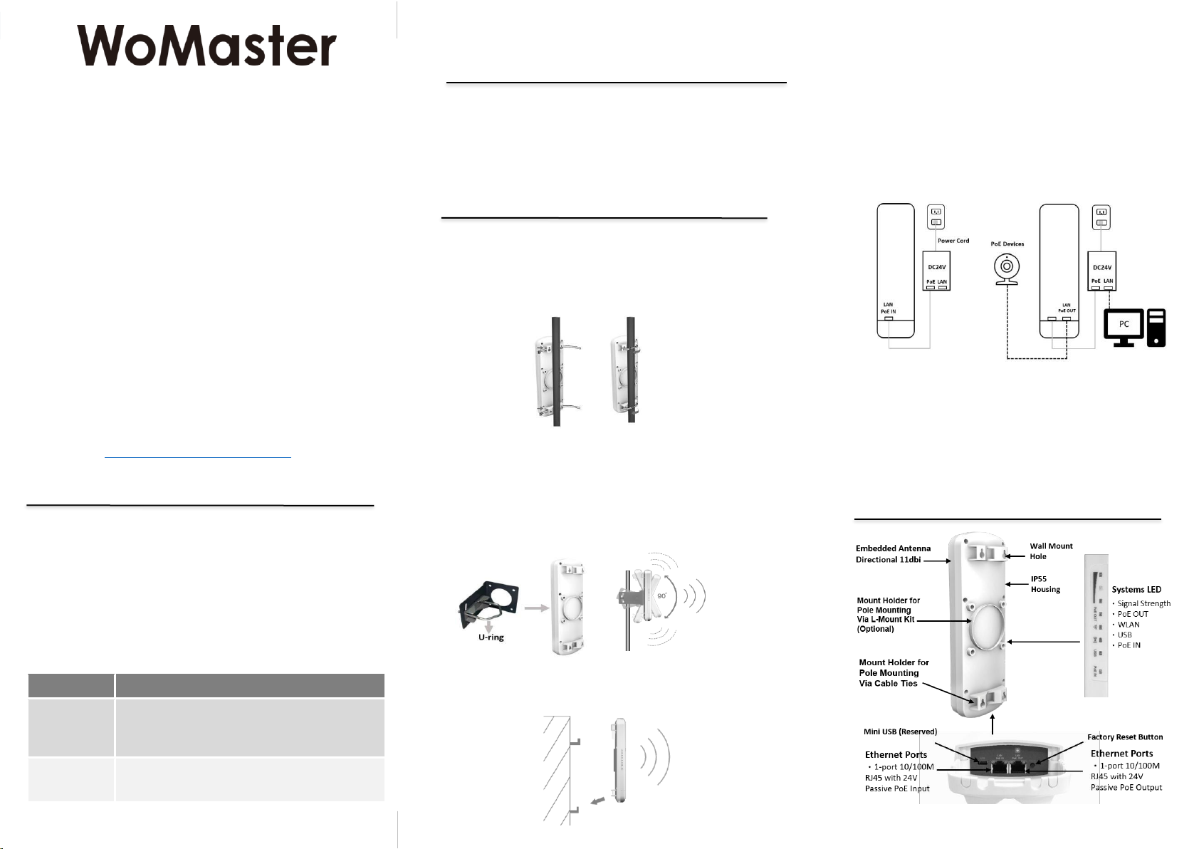
Preparation for Web management of the Root Bridge:
First, connect the device with PC by an Ethernet cable plugging in
LAN port of PoE injector in one side and in LAN port of PC in the
other side. Then power onthe device by PoE from PoE injector. And
verify that device is properly installed in the network and that every
PC of this network can access the device through the web browser
(Google Chrome, Internet Explorer, Mozilla Firefox).
•Type http://IP_address in your browser (the default IP address is
http://192.168.10.1/)
•Key in the username and password in login screen. The default
username and password are admin and admin.
•After you click OK, the Welcome page of the web-based
management interface will appear.
•On the left side you can see the list of software features, on the right
side –available settings.
To link with the device, please make sure that the IP Address of the
PC is in the same subnet (192.168.10.x). The Root Bridge has
DHCP server on by default, so you could just connect via ethernet
cable and let the Root Bridge give you a network address.
Preparation for Web management of the Client Bridge:
First, connect the device with PC by an Ethernet cable plugging in
LAN port of PoE injector in one side and in LAN port of PC in the
other side. Then power onthe device by PoE from PoE injector. And
verify that device is properly installed in the network and that every
PC of this network can access the device through the web browser
(Google Chrome, Internet Explorer, Mozilla Firefox).
•Type http://IP_address in your browser (the default IP address is
http://192.168.10.2/)
•Key in the username and password in login screen. The default
username and password are admin and admin.
•On the left side you can see the list of software features, on the right
side –available settings.
To link with the device, please make sure that the IP Address
of the PC is located in the same subnet (192.168.10.x). Note: The
Client Bridge does not have DHCP Server turned on by default.
Preparation for Telnet management:
You can connect to the device by Telnet. Below are the steps to
open Telnet connection to the device.
•Make sure that the Remote Service for Telnet Server has been
checked (Open Web GUI -> Management -> Remote Service)
•Start -> Open Command prompt ->Enter
•Type the Telnet 192.168.10.1 (orthe IP address of the device). And
then press Enter
For further feature configurations, please refer to the
User Manual.
・Support
At WoMaster, you can use the online service forms to request
the support. The submitted forms are stored in server for
WoMaster team member to assign tasks and monitor the status
of your service. Please feel free to write to help@womaster.eu
if you encounter any problems.
© WoMaster Inc. All rights reserved.
・Warranty
2-year Global warranties are available for WoMaster products
assuring our customers that the products shall remain free from
defects in workmanship or materials and conform in all material
respects to WoMaster specifications, or Purchaser’s supplied and
accepted specifications. The warranty is limited to the repair and/or
replacement, at WoMaster'sole discretion, of the defective product
during its warranty period. The customer must obtain a Return
Merchandise Authorization (RMA) approval code prior to
returning the defective Product to WoMaster for service. The
customer agrees to prepay shipping charges, to use the original
shipping container or equivalent, and to ensure the Product or
assume the risk of loss or damage in transit. Repaired or replaced
products are warranted for ninety (90) days from the date of repair
or replacement, or for the remainder of the original product's
warranty period, whichever is longer.
・Disclaimer
WoMaster reserves the right to make changes to this QIG or to the
product hardware at any time without notice. It is the user’s
responsibility to determine whether there have been any such
updates or amendments herein.
Defects, malfunctions, or failures of the warranted Product(s)
caused by damage resultingfrom unforeseeable incidents (such as
lightings, floods, fire, etc.), environmental and atmospheric
disturbances, other external forces such as power line
disturbances and surge, host computer malfunction and virus,
incorrect power input, or incorrect cabling, incorrect grounding and
damages caused by misuse, abuse and unauthorized alteration or
repair are not warranted.
https://westwardsales.com/womaster