WOOD'S POWR-GRIP MRT49DCO User manual

KEEP FOR FUTURE REFERENCE
INSTRUCTIONS
International Version
MODEL NUMBERS: MRT49DCO,
MRT4HV11DCO, MRT411LDCO
SERIAL NUMBER: ___________
(please see serial label and record number here)
MANUAL ROTATOR / TILTER
DC-VOLTAGE
WITH DUAL VACUUM SYSTEM OPTION
READ ALL INSTRUCTIONS AND WARNINGS
BEFORE OPERATING THIS LIFTER
DESIGNED FOR THE MATERIALS HANDLING PROFESSIONAL
P.O. Box 368 –908 West Main
Laurel, MT USA 59044
phone 800-548-7341
phone 406-628-8231
fax 406-628-8354


Rev 12.0/5-13 1 MRT4-DCO-DVS: #35071
TABLE OF CONTENTS
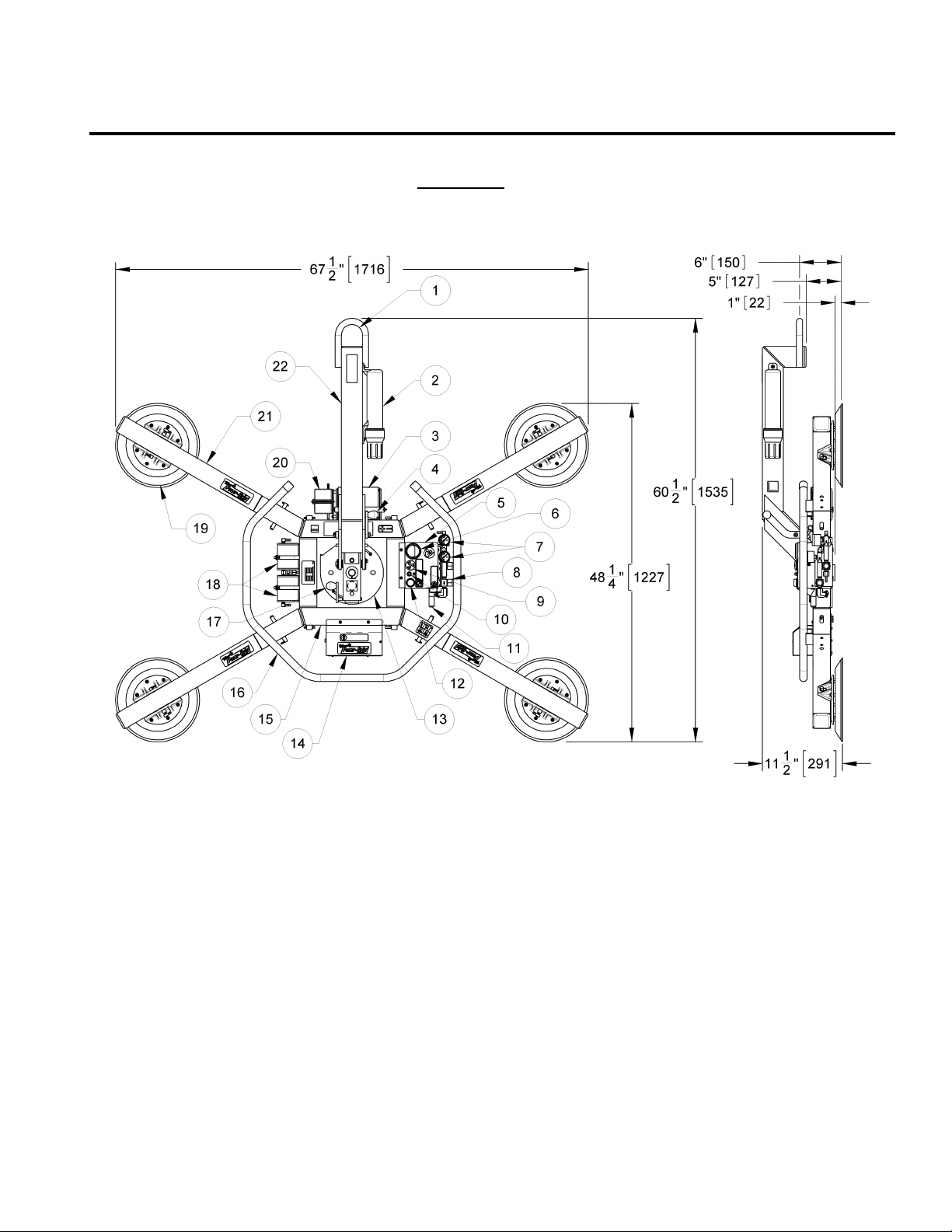
SPECIFICATIONS............................................................................................................ 3
WARNINGS ..................................................................................................................... 4
OPERATING FEATURES................................................................................................... 5
ASSEMBLY....................................................................................................................... 6
TO SET UP THE LIFTER ................................................................................................................ 6
TO CHANGE THE PAD FRAME CONFIGURATION ................................................................................6
Basic Configuration ......................................................................................................................................7
Linear Configuration.....................................................................................................................................7
Extended Configuration ................................................................................................................................7
Secondary Rotation Stops.............................................................................................................................7
INTENDED USE ............................................................................................................... 8
LOAD CHARACTERISTICS ............................................................................................................. 8
OPERATING ENVIRONMENT .........................................................................................................9
DISPOSAL OF THE LIFTER ............................................................................................................ 9
OPERATION .................................................................................................................. 10
BEFORE USING THE LIFTER........................................................................................................10
Taking Safety Precautions ..........................................................................................................................10
Performing Inspections and Tests ...............................................................................................................10
TO APPLY THE PADS TO A LOAD..................................................................................................11
Positioning the Lifter on the Load ...............................................................................................................11
Sealing the Pads against the Load...............................................................................................................11
Reading the Vacuum Gauges ......................................................................................................................12
Vacuum Level on Optimal Surfaces .............................................................................................................12
Vacuum Level on Other Surfaces ................................................................................................................12
TO LIFT AND MOVE THE LOAD ....................................................................................................13
Positioning the Lift Bar ...............................................................................................................................13
Load Capacity and the Warning Light ..........................................................................................................13
Monitoring Vacuum Indicators ....................................................................................................................13
Low Vacuum Warning Buzzer .....................................................................................................................14
Controlling the Lifter and Load....................................................................................................................14
In Case of Power Failure ............................................................................................................................14
TO ROTATE THE LOAD EDGEWISE................................................................................................ 15
TO TILT THE LOAD ...................................................................................................................16
TO RELEASE THE PADS FROM THE LOAD .......................................................................................16
AFTER USING THE LIFTER..........................................................................................................17
Storing the Lifter........................................................................................................................................17

Rev 12.0/5-13 2 MRT4-DCO-DVS: #35071
MAINTENANCE ............................................................................................................. 18
INSPECTION SCHEDULE.............................................................................................................18
Every-Lift Inspection ..................................................................................................................................18
Frequent Inspection ...................................................................................................................................18
Periodic Inspection.....................................................................................................................................18
Infrequent Use...........................................................................................................................................19
TESTING SCHEDULE..................................................................................................................19
Operational Tests.......................................................................................................................................19
Load Test ..................................................................................................................................................19
MAINTENANCE SCHEDULE..........................................................................................................20
BATTERY TEST .........................................................................................................................20
BATTERY RECHARGE .................................................................................................................20
BATTERY CHARGER TEST ...........................................................................................................21
VACUUM PAD MAINTENANCE......................................................................................................21
Friction Coefficient .....................................................................................................................................21
Inspection .................................................................................................................................................21
Cleaning ....................................................................................................................................................22
VACUUM TEST .........................................................................................................................23
AIR FILTER MAINTENANCE ........................................................................................................24
Filter Function and Conditions Requiring Service ..........................................................................................24
Filter Service Procedures ............................................................................................................................24
VACUUM PUMP MAINTENANCE −DYNAFLO DV1032102 ...............................................................25
Replacing the Diaphragm ...........................................................................................................................25
Replacing the Gasket/Flap Valves................................................................................................................25
Replacing the Head Assembly .....................................................................................................................25
VACUUM PUMP MAINTENANCE −THOMAS 107CDC20 ..................................................................26
Replacing the Diaphragm ...........................................................................................................................26
Replacing the Intake Valve Flapper .............................................................................................................26
Replacing the Exhaust Valve Flapper and Head Gasket .................................................................................26
VACUUM SWITCH ADJUSTMENT ..................................................................................................27
Vacuum Switch Function ............................................................................................................................27
Conditions Requiring Readjustment .............................................................................................................27
Adjustment Procedure ................................................................................................................................28
REPLACEMENT PARTS LIST .......................................................................................... 29
LIMITED WARRANTY.................................................................................................... 30

Rev 12.0/5-13 3 MRT4-DCO-DVS: #35071
SPECIFICATIONS
Power Source:
12 volts DC, 10 amps (with Thomas pump) or 3 amps (with Dynaflo pump)
Battery Capacity:
7 amp-hours
Rotation Capability:
Manual, 360°, with automatic locking at each ¼ revolution (when desired)
Tilt Capability:
Manual, 90°, with automatic locking in vertical position
Vacuum Pump:
Diaphragm type, 1 SCFM [28 liters/minute] nominal airflow
Vacuum Reserve Tanks:
Vacuum reservoirs help prevent immediate vacuum loss in case of power failure and extend
battery life by reducing pump cycles required to maintain vacuum.
Vacuum Gauges:
Dial gauges indicate current vacuum level in positive inches of Hg and negative kPa.
Low Vacuum Warning Light: Red light is energized until vacuum level is sufficient to lift maximum load weight (higher than
16" Hg [-54 kPa]) and whenever vacuum loss causes pump to re-engage.
Low Vacuum Warning Buzzer: Maximum Alarm Volume = 103 dBA at 2 ft [60 cm]. While the lifter is powered up, an audible
alarm warns the operator whenever vacuum is not sufficient for lifting the maximum load weight.
Options:
Model EO10DVS - Dual Vacuum System. Two vacuum system circuits allow the lifter to maintain
the vacuum level in one circuit even if an unexpected vacuum loss occurs in the other one (eg,
due to load breakage). See separate instructions about other options.
Operating Elevation:
Maximum = 6000 ft [1828 meters]
Operating Temperatures:
32° to 104° F [0° to 40° C]
Service Life:
This lifter is designed to have a service life of at least 20,000 lifting cycles, when used and
maintained as intended. Vacuum pads, filter elements and other wear-out items are excluded;
see MAINTENANCE and REPLACEMENT PARTS LIST for more information. For the DISPOSAL OF THE
LIFTER after its service life, see INTENDED USE.
ASME Standard BTH-1:
Design Category "B", Service Class "0" (see www.powrgrip.com for more information)
!!-CE-!! Note: This symbol appears in the
INSTRUCTIONS
manual only when requirements of a CE Standard are
different
from
requirements of other standards that also apply to this vacuum lifter. CE requirements are mandatory in geographical areas
where CE Standards apply, but may be optional in other locations.
1Optionally available with closed-cell foam rings for rough or textured surfaces (Model MRT4HV11FDCO), as well as alternative
rubber compounds for special applications (see REPLACEMENTS PARTS LIST).
2Load Capacity is based on a friction coefficient of 1; see MAINTENANCE: VACUUM PAD MAINTENANCE: Friction Coefficient for
additional information.
Description:
Designed for use with a crane or other hoisting equipment, MRT4-DC lifters employ vacuum to
hold a load for lifting, and they provide manual 360° rotation and manual 90° tilt movements for
load manipulation.
Model Number:
MRT49DCO
MRT4HV11DCO
MRT411LDCO
Vacuum Pads:1
9" [23 cm] nominal
diameter (Model VPFS9)
10" [25 cm] nominal dia.,
lipped (Model HV11)
11" [28 cm] nominal dia.,
lipped (Model G3370)
(Four, standard rubber, spring-mounted for ¼" [7 mm] travel, with #60 filter screen)
Maximum Pad Spread: (to outer edges)
Extended Configuration:
45¼" x 64¾"
47¼" x 66½"
48¼" x 67½"
[1152 mm x 1643 mm]
[1201 mm x 1690 mm]
[1227 mm x 1716 mm]
Basic Configuration:
25¼" x 30"
27¼" x 31¾"
28¼" x 32¾"
[642 mm x 760 mm]
[693 mm x 807 mm]
[717 mm x 834 mm]
Linear Configuration:
12¾" x 75¼"
14½" x 77¼"
15¾" x 78¼"
[323 mm x 1914 mm]
[369 mm x 1963 mm]
[397 mm x 1988 mm]
Load Capacity:
(rated at 16" Hg [-54 kPa] on clean, smooth, nonporous flat surfaces)2
Per-Pad:
125 lbs [56.5 kg]
150 lbs [68 kg]
175 lbs [80 kg]
Maximum:
500 lbs [225 kg]
600 lbs [270 kg]
700 lbs [320 kg]
Lifter Weight:
135 lbs [62 kg]

Rev 12.0/5-13 4 MRT4-DCO-DVS: #35071
WARNINGS
Powr-Grip is pleased to offer the most reliable vacuum lifters available.
Despite the high degree of security provided by this product, certain
precautions must be observed to protect the operator and others.
Always
wear personal protective equipment that is appropriate for the material being handled.
Follow trade association guidelines.
Always
operate the lifter under conditions approved for its design (see INTENDED USE:
OPERATING ENVIRONMENT).
Never
operate a lifter that is damaged, malfunctioning, or missing parts.
Never
operate a lifter if the sealing edge of any vacuum pad is cut or otherwise damaged.
Never
remove or obscure warning labels.
Never
operate a lifter if the Load Capacity or any warning appears to be missing or obscured.
Always
make certain the contact surfaces of the load and all vacuum pads are clean prior to
applying the pads (see MAINTENANCE: VACUUM PAD MAINTENANCE).
Never
exceed the Load Capacity or attempt to lift loads the lifter is not designed for (see
INTENDED USE: LOAD CHARACTERISTICS).
Never
attempt to lift cracked or broken glass with this lifter.
Always
position the vacuum pads correctly on the load prior to lifting (see OPERATION: TO APPLY
THE PADS TO A LOAD).
Never
lift a load when any vacuum indicator shows inadequate vacuum.
Never
touch the vacuum release controls during a lift. This may result in loss of vacuum and
release of the load.
Never
allow people to ride on the lifter or the load being lifted.
Never
lift a load higher than necessary or leave suspended loads unattended.
Never
lift a load over people.
Always
keep other personnel far enough away from the lifter to avoid injury in the event of an
unexpected load release.
Always
place the power control in the inactive position and, when possible, disconnect the
power source before opening any enclosure on the lifter. (Only applicable to powered lifters)
Always
remember that modifications to the lifter may compromise its safety. Wood’s Powr-Grip
cannot be responsible for the safety of a lifter that has been modified by the customer. For
consultation, contact Wood's Powr-Grip (see LIMITED WARRANTY).
Never
disengage both the rotation latch and the tilt latch at the same time.

Rev 12.0/5-13 5 MRT4-DCO-DVS: #35071
OPERATING FEATURES
Note: Components featured in the following instructions for assembling, operating or
maintaining the vacuum lifter are underlined on their first appearance in each section.
Standard MRT411LDC shown with Dual Vacuum System option.
1 LIFT BAIL
8 AIR FILTER
16 CONTROL HANDLE
2 INSTRUCTIONS CANISTER
9 LOW VACUUM WARNING BUZZER
17 ROTATION RELEASE LEVER
3 BATTERY
10 BATTERY TEST BUTTON
18 VACUUM RESERVE TANKS
4 TILT RELEASE LEVER
11 VALVE HANDLE
19 VACUUM PAD
5 Enclosure with VACUUM SWITCHES
12 LOW VACUUM WARNING LIGHT
20 BATTERY CHARGER
6 BATTERY GAUGE
13 ROTATION WEAR PLATE
21 EXTENSION ARM
7 VACUUM GAUGES
14 Cover for VACUUM PUMP
22 LIFT BAR
15 PAD FRAME

Rev 12.0/5-13 6 MRT4-DCO-DVS: #35071
ASSEMBLY
TO SET UP THE LIFTER
1) Open the shipping container and remove all materials for restraining or protecting the vacuum
lifter. Save the container for use whenever the lifter is transported.
2) Suspend the lifter from a crane as follows: Select hoisting equipment (crane and hoist, when
applicable) rated to carry the maximum load weight plus the lifter weight (see
SPECIFICATIONS: Maximum Load Capacity and Lifter Weight).
Note: Any application of the lifter must conform to all statutory or regulatory standards that
relate to the hoisting equipment when used in its geographical location (eg, relevant OSHA
standards in the USA).
Disengage the tilt latch (see OPERATION: TO TILT THE LOAD) and raise the lift bar to a vertical
orientation. Then attach the hoisting equipment hook to the lift bail.
WARNING: Hoisting equipment hook must be fitted with restraining latch to
prevent lift bail from slipping off under any circumstances.
Note: Some hoisting equipment hooks could interfere with an upright load that extends
beyond the lifter's pad frame. If the load would contact the hook during lifter operation, the
operator must prevent this by attaching a sling (or other rigging that does not interfere with
the load) between the hook and the lift bail.
WARNING: Any sling used must be rated to carry maximum load weight plus
lifter weight.
Use the hoisting equipment to raise the lifter out of the shipping container. Be careful to
avoid damaging any vacuum pads. Remove the pad covers and save them for use whenever
the lifter is stored.
3) Arrange the pad frame in the configuration that will provide optimal support of the load while
lifting (see TO CHANGE THE PAD FRAME CONFIGURATION to follow).
4) Connect the electrical connectors uniting the battery to the battery charger and the vacuum
generating system. Now the lifter is operational.
5) Perform Operational and Load Tests for the lifter as directed in MAINTENANCE: TESTING
SCHEDULE.
TO CHANGE THE PAD FRAME CONFIGURATION
This lifter offers a variety of pad frame configurations to accommodate different load dimensions
(see SPECIFICATIONS: Maximum Pad Spread). Configurations are created by installing or
removing the pad frame’s extension arms and by repositioning the vacuum pads, which have
movable mounts.
Select a configuration to provide optimal support across the load surface and to minimize load
overhang. Assemble the pad frame in a symmetrical arrangement, to keep the lifter balanced,

Rev 12.0/5-13 7 MRT4-DCO-DVS: #35071
and make sure all vacuum hoses are secure and routed to avoid being pinched, snagged,
abraded or otherwise damaged while the lifter is in operation.
WARNING: Make sure all vacuum hoses are coiled or routed so they cannot
become entangled, kinked or punctured during rotation or tilt.
MRT411LDC shown; see SPECIFICATIONS for other models’ Maximum Pad Spread.
Basic Configuration
This configuration provides a small, rectangular pad spread. Remove all 4 extension arms and
mount the vacuum pads directly to the arm sockets on the main pad frame. Note: Keep one set
of cotterless hitch pins with the extension arms at all times.
Linear Configuration
This configuration provides a narrow, rectangular pad spread. Remove 2 extension arms from
opposite sides of the lifter but leave the other 2 extension arms in place, as shown. Mount the
remaining vacuum pads at the arm sockets on the main pad frame. Then adjust the rotation
wear plate to utilize the secondary rotation stops (see discussion to follow).
Extended Configuration
This configuration provides a large, rectangular pad spread. Insert all 4 extension arms in the
main pad frame and secure them with the cotterless hitch pins provided. Mount the vacuum
pads at the outer ends of the arms, using the second set of cotterless hitch pins.
Secondary Rotation Stops
The lifter features a second set of rotation stops rotated 30° from the primary stops. The
secondary stops provide level load positioning when the pad frame is in the Linear Configuration
(see discussion preceding). To use these stops, loosen the two screws that secure the rotation
wear plate. Rotate the plate 30° counter-clockwise, to align the second set of stops with the
holes in the wear plate. Tighten the screws to secure the wear plate. Reverse this procedure to
realign the primary stops for use with the other pad frame configurations.

Rev 12.0/5-13 8 MRT4-DCO-DVS: #35071
INTENDED USE
LOAD CHARACTERISTICS
WARNING: This lifter is NOT intended for lifting hazardous materials, such as
explosives or radioactive substances.
The operator must verify that the lifter is intended to handle each load, in accordance with the
following requirements:
• The load must not exceed the maximum allowable weight specified under Load Capacity (see
SPECIFICATIONS).
• The load must be a single piece of nonporous or semiporous material with a flat and relatively
smooth contact surface.3To determine whether the load is too porous or rough, perform the
test under Vacuum Level on Other Surfaces (see OPERATION: TO APPLY THE PADS TO A LOAD).
• The load's contact surface must be suitable for obtaining a friction coefficient of 1 with the
lifter's vacuum pads (see MAINTENANCE: VACUUM PAD MAINTENANCE: Friction Coefficient), as
verified by a friction test. If necessary, contact Wood's Powr-Grip for help in conducting a
friction test.
• In order to avoid damaging the vacuum pads, the load's surface temperature must not exceed
the allowable Operating Temperatures (see SPECIFICATIONS). However, if such an
application cannot be avoided, Wood's Powr-Grip does offer a heat-resistant rubber
compound and other solutions which may enable you to lift loads with higher surface
temperatures. Contact Wood’s Powr-Grip or an authorized dealer for more information.
•While the
minimum
length and width of the load are determined by the Pad Spread (see
SPECIFICATIONS), the
maximum
length and width are determined by the allowable
overhang, or the amount of load material that can extend sideways beyond the vacuum pads
without breaking or otherwise being damaged.
The allowable overhang depends on the kind of load material being lifted, the thickness of the
material, and the angle at which it is handled (if any). Since materials such as glass, stone or
sheet metal each have different physical properties, the allowable overhang must be
evaluated separately for each type of load. If necessary, contact Wood’s Powr-Grip or an
authorized dealer for help in determining the recommended overhang in a specific situation.
• 1" [2.5 cm] is the maximum allowable thickness of loads at the maximum weight (see
SPECIFICATIONS: Load Capacity). However, allowable thickness increases as load weight
decreases. If necessary, contact Wood’s Powr-Grip for help in determining the maximum
thickness permitted when handling any specific load.
Note: Vacuum pads can stain or deform load surfaces with light colors or soft coatings. The
operator should test such surfaces for detrimental effects before using the lifter on them.
3Lifters that feature concave vacuum pads can also attach to some kinds of curved loads. Since curvature affects the lifting
capacity, contact Wood’s Powr-Grip for help in determining the Load Capacity for a particular curved load.

Rev 12.0/5-13 9 MRT4-DCO-DVS: #35071
OPERATING ENVIRONMENT
The operator must determine whether the lifter is intended to be used in each work environment,
in accordance with the following restrictions:
WARNING: Never use lifter in dangerous environments.
• This lifter is not intended for use in any environment that is inherently dangerous to the
operator or likely to compromise the lifter's ability to function. Environments containing
explosives, caustic chemicals and other dangerous substances must be avoided when using
the lifter.
• The lifter's work environment is limited by the Operating Elevation and Operating Temperatures
indicated in SPECIFICATIONS.
• The lifter's work environment must be free of metal particles or any other contaminates that
could damage lifter components through airborne contact or any other means of transmission
in the environment. If such contaminates cause a vacuum pump failure, they could result in a
load release and possible injury to the operator or others nearby.
WARNING: Environmental contaminates could result in vacuum pump failure.
• Using the lifter in wet environments may require the operator to take special precautions:
Moisture on contact surfaces of the load or vacuum pads diminishes the lifter’s slip resistance,
thereby reducing the lifting capacity (see MAINTENANCE: VACUUM PAD MAINTENANCE: Friction
Coefficient).
WARNING: Moisture reduces slip resistance of vacuum pads.
Although the lifter's exterior surfaces can tolerate some exposure to water vapor, they are not
designed to be water-tight. Submerging the lifter or using it in rain may damage lifter
components; these and similar conditions must be avoided.
DISPOSAL OF THE LIFTER
After the vacuum lifter has reached the end of its service life, you must dispose of the lifter in
compliance with all local codes and regulatory standards that are relevant for the geographical
region.
Note: This lifter is equipped with a battery, which may be subject to special disposal regulations.

Rev 12.0/5-13 10 MRT4-DCO-DVS: #35071
OPERATION
BEFORE USING THE LIFTER
The operator must determine whether the lifter is capable of performing each intended task, in
accordance with the SPECIFICATIONS and INTENDED USE sections of this
INSTRUCTIONS
manual. In addition, all of the following preparations must be completed prior to lifting any load.
Taking Safety Precautions
The operator must be trained in all relevant industry and regulatory standards for the operation
of the vacuum lifter in its geographical location (eg, ASME B30.20 in the USA).
The operator must read and understand this
INSTRUCTIONS
manual, including all
WARNINGS
,
before using the lifter. If necessary, contact Wood’s Powr-Grip or an authorized dealer for
assistance.
WARNING: Always wear appropriate personal protective equipment.
The operator must wear any personal protective equipment and take any other precautions
required to handle the load safely. Consult appropriate trade association guidelines to determine
what precautions are necessary for each type of load material.
Performing Inspections and Tests
WARNING: Always check battery energy before using lifter.
(See MAINTENANCE: BATTERY TEST)
Perform all inspections and tests required by the INSPECTION and TESTING
SCHEDULES (see MAINTENANCE). In addition, if the lifter has been in
storage, always conduct a VACUUM TEST before placing it in service (see
MAINTENANCE).
WARNING: Make sure alarm is clearly audible over ambient noise at operator
position.
The volume of the alarm may be adjusted by rotating the shutter of the low vacuum warning
buzzer. Make sure the alarm is loud enough to be heard over any other noise that may be
present while the lifter is in use. In addition, the alarm must be clearly audible at the maximum
distance the operator may be from the lifter, as well as through any barriers or obstructions
between the operator and the lifter. In order to be considered clearly audible,
the alarm
volume must exceed ambient noise by at least 15 dBA at the operator position.
4Since
the Maximum Alarm Volume is 103 dBA, ambient noise must not exceed 88 dBA under any
circumstances. Furthermore, if ambient noise measures 88 dBA, the alarm volume must be set
to maximum and the operator must remain within 2 ft [60 cm] of the warning buzzer, in order for
it to be effective.
4Consult CE Standard EN 457 for alternative ways to determine whether the alarm is clearly audible to operators.

Rev 12.0/5-13 11 MRT4-DCO-DVS: #35071
CAUTION: Examine each air filter regularly, and empty when necessary.
Two air filters help protect the vacuum generating system from contaminants. However, the
lifter is not intended for use on wet load surfaces because the filters would not prevent liquid
from entering the vacuum system. The operator must examine each filter bowl regularly and
remove any liquid or other contaminants found inside (see MAINTENANCE: AIR FILTER
MAINTENANCE).
TO APPLY THE PADS TO A LOAD
Positioning the Lifter on the Load
Make certain that the contact surfaces of the load and all vacuum pads are free of any
contaminates that could prevent the pads from sealing against the load (see MAINTENANCE:
VACUUM PAD MAINTENANCE).
Center the lifter’s rotation axis to within 2" [5 cm] of the load center, since off-center loading can
cause the load to rotate or tilt unexpectedly (see TO ROTATE THE LOAD EDGEWISE or TO TILT THE LOAD
to follow), and it may also damage the lifter.5Make sure that all vacuum pads will fit entirely on
the load’s contact surface (see SPECIFICATIONS: Pad Spread) and that they will be loaded
evenly while lifting (see SPECIFICATIONS: Per-Pad Load Capacity). Then apply the lifter to the
load so that all pads are touching the contact surface.
Sealing the Pads against the Load
Firm pressure at the center of the lifter
helps the vacuum pads begin to seal
against the load. Pull the valve handle
outward until it latches securely in the
“APPLY” position (power on), as shown.
This energizes the vacuum pump, causing
air to be drawn at the pads immediately.
The red low vacuum warning light also
turns on and remains illuminated until the lifter attains sufficient vacuum to lift the maximum
load weight (see TO LIFT AND MOVE THE LOAD: Load Capacity and the Warning Light to follow). The
valve handle must remain in the “APPLY” position throughout the entire lift.
WARNING: Keep valve handle latched securely in “APPLY” position throughout
lift.
Note: If a vacuum pad has been lying against a hard object (as during shipping), it may be
slightly distorted. Although initially it may be difficult to apply the pad to a load, this condition
should correct itself with continued use.
5The lifter is designed to handle the maximum load weight (see SPECIFICATIONS: Maximum Load Capacity) when the load’s
center of gravity is positioned within 2" [5 cm] of the lifter’s rotation axis. Occasional loading deviations are permissible, provided
that the operator can maintain control of the load at all times and that the load weight is low enough to avoid damaging the lifter.
TO APPLY

Rev 12.0/5-13 12 MRT4-DCO-DVS: #35071
Reading the Vacuum Gauges
The lifter is equipped with 2 vacuum gauges, which indicate the current vacuum level in each
circuit of the lifter’s vacuum system. The
green
range indicates vacuum levels sufficient for
lifting the maximum load weight, whereas the
red
range indicates vacuum levels that are
not
sufficient for lifting the maximum load weight. Both gauge needles should show a sudden surge
in vacuum as the vacuum pads seal against the load. If it takes more than 5 seconds for the
vacuum level to reach 5" Hg [-17 kPa] on either vacuum gauge, press on any pad that has not
yet sealed.
Vacuum Level on Optimal Surfaces
When the lifter is attached to clean, smooth, nonporous load surfaces, it should be able to
maintain a vacuum level in the green range on both vacuum gauges, except when used at high
elevations (see SPECIFICATIONS: Operating Elevation). If not, make sure both vacuum switches
are adjusted correctly (see MAINTENANCE: VACUUM SWITCH ADJUSTMENT). If either vacuum switch
cannot be adjusted to maintain a vacuum of 16" Hg [-54 kPa], perform the VACUUM TEST (see
MAINTENANCE) to determine whether there is a deficiency in the vacuum generating system.
Vacuum Level on Other Surfaces
When the lifter is attached to contaminated, rough or porous load surfaces, it may not be able to
maintain a vacuum level in the green range on both vacuum gauges, due to leakage in the seal
between the vacuum pads and the load surface.6In the case of contamination, thoroughly clean
the contact surfaces of the load and the vacuum pads (see MAINTENANCE: VACUUM PAD
MAINTENANCE: Cleaning), and reapply the lifter to the load. If the load has rough or porous
surfaces,
the operator must conduct a test to determine whether the lifter is designed
to lift the load
, as follows:
1) Make sure the lifter's vacuum generating system is functioning correctly (see MAINTENANCE:
VACUUM TEST).
2) Apply the vacuum pads to the load as previously directed.
3) After the vacuum pump stops running, disconnect the electrical connector uniting the battery
with the vacuum generating system.
Note: After the test is completed, move the valve handle to the “RELEASE” position (power
off
) before reconnecting the battery.
4) Raise the load a minimal distance, to assure that it is supported by the lifter.
5) Monitor both vacuum gauges while the load is suspended for 5 minutes:
The lifter must
maintain a minimum vacuum level of 10" Hg [-34 kPa] during this time.
If not, the
load does not possess the characteristics required for using this lifter.7
6Contaminated loads can also cause the vacuum pump to run frequently or continuously. Since excessive pumping quickly
reduces battery energy, the operator should clean the load when possible, to minimize pumping.
7Certain load materials are too rough or porous to allow the lifter to form a seal which can be maintained for 5 minutes without
power. However, in geographical locations where CE Standards do not apply, it may be possible to use the lifter to lift such loads.
Contact Wood’s Powr-Grip for more information.

Rev 12.0/5-13 13 MRT4-DCO-DVS: #35071
TO LIFT AND MOVE THE LOAD
Positioning the Lift Bar
WARNING: Lift bar must be oriented vertically to lift
load.
Never lift the load from a flat position with the lift bar latched parallel
to the load. Always disengage the tilt latch (see TO TILT THE LOAD to
follow) and raise the lift bar to a vertical orientation before attempting to lift.
Load Capacity and the Warning Light
A lifter's Load Capacity is rated at a vacuum level of 16" Hg [-54 kPa] (see SPECIFICATIONS).
After the lifter has attained this level, the vacuum pump turns off automatically, to conserve
battery energy. At the same time, the low vacuum warning light turns off, to indicate that the
lifter is ready to lift the maximum load weight.
WARNING: Never attempt to lift load while red warning light is illuminated.
Do not attempt to lift the load while the warning light is illuminated; such an attempt could result
in a load release and possible injury to the operator.
Monitoring Vacuum Indicators
The low vacuum warning light and both vacuum gauges must remain completely visible to the
operator, so that they can be monitored throughout the entire lift.
WARNING: Vacuum indicators must be visible to operator throughout entire lift.
If the vacuum system experiences leakage while the lifter is attached to the load, the vacuum
pump turns on automatically, as required to maintain sufficient vacuum for lifting the maximum
load weight. The low vacuum warning light also turns on and remains illuminated while the
pump is running, to signal the reduction in vacuum to the operator.
If the pump and warning light turn on while you are lifting a load, make sure both vacuum
gauges show a vacuum level of 16" Hg [-54 kPa] or higher. If not, move away and stay clear of
the load until it can be lowered to the ground or a stable support.
WARNING: Stay clear of any suspended load while vacuum level is lower than
16" Hg [-54 kPa].
Discontinue lifter use until the cause of the vacuum loss can be determined. If the pump runs at
intervals of ten minutes or less while the lifter is attached to clean, smooth, nonporous materials,
the leakage is likely to be in the vacuum system. In this event, perform the VACUUM TEST (see
MAINTENANCE) and inspect the vacuum pads for damage (see MAINTENANCE: VACUUM PAD
MAINTENANCE: Inspection). If the vacuum loss cannot be remedied immediately, perform
inspection and maintenance as needed to identify and correct any deficiency before resuming
normal operation of the lifter.

Rev 12.0/5-13 14 MRT4-DCO-DVS: #35071
Low Vacuum Warning Buzzer
Using the low vacuum warning buzzer requires minimal interaction from the operator. The
warning buzzer sounds an alarm until the lifter attains sufficient vacuum to lift the maximum load
weight (see SPECIFICATIONS: Load Capacity). After the lifter has attained this vacuum level, the
alarm stops sounding, to indicate that the lifter is ready to lift the load.
WARNING: Never attempt to lift load while alarm is sounding.
Do not attempt to lift the load while the alarm is sounding; such an attempt could result in a load
release and possible injury to the operator.
If the vacuum system experiences leakage while the lifter is attached to the load, the vacuum
pump turns on automatically, as required to maintain sufficient vacuum. The alarm also sounds
while the pump is running, to signal the reduction in vacuum to the operator. If the alarm
sounds while you are lifting a load, make sure the vacuum gauge shows a vacuum level of 16"
Hg [-54 kPa] or higher. If not, immediately move away and stay clear of the load until it can be
lowered to the ground or a stable support.
WARNING: Stay clear of any suspended load while alarm is sounding.
Discontinue lifter use until the cause of the vacuum loss can be determined. Using the lifter on
contaminated, rough or porous surfaces may result in a vacuum loss, due to leakage between
the vacuum pads and the load. Since the alarm may sound in such circumstances, consult the
section TO APPLY THE PADS TO A LOAD: Vacuum Level on Other Surfaces to determine whether the
lifter can be used to lift the load. If the vacuum loss is due to any other cause, perform
inspection and maintenance as needed to identify and correct any deficiency before resuming
normal operation of the lifter.
Controlling the Lifter and Load
When the vacuum indicators show that the lifter is ready, use the hoisting equipment to raise the
lifter and load as needed to clear any obstacles in their path. Use the control handle to keep the
lifter and load in the desired orientation while they are suspended from the crane. Once
sufficient clearance is established, the load can be rotated or tilted as desired (see TO ROTATE THE
LOAD EDGEWISE or TO TILT THE LOAD to follow).
In Case of Power Failure
The lifter is equipped with 2 vacuum reserve tanks, designed to maintain vacuum temporarily in
case of a power failure (ie, in battery).
WARNING: Stay clear of any suspended load in the event of a power failure.
Although the lifter is designed to support the load for at least 5 minutes without power, this
depends on many factors, including the condition of the load and the lifter’s vacuum system (see
INTENDED USE: LOAD CHARACTERISTICS and MAINTENANCE: VACUUM PAD MAINTENANCE,VACUUM
TEST). If a power failure occurs, keep all personnel clear of the suspended load until it can safely
be placed on the ground or a stable support. Correct any deficiency before resuming normal
operation of the lifter.

Rev 12.0/5-13 15 MRT4-DCO-DVS: #35071
TO ROTATE THE LOAD EDGEWISE
WARNING: Never disengage both the rotation latch and the tilt latch at the
same time.
This lifter is not designed for rotation and tilt functions to be used at the same time. Disengaging
the rotation and tilt latches simultaneously could cause uncontrolled and unpredictable load
movement, potentially resulting in load damage or injury to the operator.
WARNING: Make sure load is positioned correctly on lifter (see TO APPLY);
unbalanced loads may rotate unexpectedly when latch is
disengaged.
Remember that the load is longer in its diagonal dimensions than in its side
dimensions. Make sure there is sufficient clearance for the load to rotate
without contacting the operator or any nearby objects. Maintain a firm grip
on the control handle to keep the load under control at all times. Pull the
rotation release lever to disengage the rotation latch, and rotate the load to
the desired position. To stop the load’s motion automatically at each
quarter turn, simply let go of the rotation release lever immediately after
initiating the rotation, so that the rotation latch engages at the next stop.
Whenever rotation is not required, keep the rotation latch engaged, to
prevent accidental damage to the load and possible injury to the operator.

Rev 12.0/5-13 16 MRT4-DCO-DVS: #35071
TO TILT THE LOAD
WARNING: Never disengage both the rotation latch and the tilt latch at the
same time.
This lifter is not designed for rotation and tilt functions to be used at the same time. Disengaging
the rotation and tilt latches simultaneously could cause uncontrolled and unpredictable load
movement, potentially resulting in load damage or injury to the operator.
WARNING: Make sure load is positioned correctly on lifter (see TO APPLY);
unbalanced loads may tilt unexpectedly when latch is disengaged.
Remember that the load requires more vertical space when tilted
to the upright position, as well as more horizontal space when
tilted to the flat position. Make sure there is sufficient clearance
for the load to tilt without contacting the operator or any nearby
objects. Maintain a firm grip on the control handle to keep the
load under control at all times. If the pad frame is latched in the
vertical position, pull the tilt release lever to disengage the tilt
latch, and prepare for a slight surge of motion as the load begins
to tilt. If load size permits, maintain control with the handle
throughout the tilt. For loads with overhang, it may be necessary
to release the control handle as the load approaches the flat
position. If so, keep the load under control using hand cups or other appropriate means. The
pad frame automatically latches in place when it returns to the vertical position.
TO RELEASE THE PADS FROM THE LOAD
WARNING: Load must be fully supported before releasing vacuum pads.
When the load is at rest and fully
supported, pinch the valve release lever
against the valve handle, to unlatch the
handle. Then push the valve handle
inward to the “RELEASE” position (power
off), as shown. Do not attempt to move
the lifter until the vacuum pads
disengage completely from the load.
TO RELEASE

Rev 12.0/5-13 17 MRT4-DCO-DVS: #35071
AFTER USING THE LIFTER
Leave the valve handle in the “RELEASE” position (power off).
CAUTION: Do not set the lifter against any surfaces which could soil or damage the
vacuum pads.
Use the hoisting equipment to gently lower the lifter onto a stable support; then detach the
hoisting equipment hook from the lift bail.
If the lifter is transported to another location, use the original shipping container and secure the
lifter so as to protect the vacuum pads and all other components from damage while in transit.
Storing the Lifter
Use the covers supplied to keep the vacuum pads clean.
!!-CE-!! In accordance with CE Standard EN 13155, the lifter is designed to rest on relatively
horizontal surfaces without tipping over. To store the lifter in this way, set the lifter with the
pads facing downward on a clean, smooth, flat surface. Then lower the lift bar to a horizontal
orientation and place a support under the lift bail.
Charge the battery completely when placing it in storage and at six-month intervals thereafter
(see MAINTENANCE: BATTERY RECHARGE). After charging the battery, disconnect the electrical
connectors uniting the battery to the battery charger and to the vacuum generating system, in
order to minimize power drainage. Preferred temperatures for storing the battery are 32° to 70°
Fahrenheit [0° to 21° Celsius]. Higher temperatures require the battery to be charged more
frequently. Storage at temperatures above 100° Fahrenheit [38° Celsius] should be avoided.

Rev 12.0/5-13 18 MRT4-DCO-DVS: #35071
MAINTENANCE
WARNING: Always make sure battery is disconnected before servicing lifter.
Note: One or more wiring diagrams are provided in the final section of this
INSTRUCTIONS
manual for reference when servicing the lifter or trouble-shooting a deficiency.
INSPECTION SCHEDULE
Perform inspections routinely, according to the following frequency schedule:
Every-Lift Inspection
• Examine the vacuum pads and load surface for contamination or debris (see VACUUM PAD
MAINTENANCE to follow).
• Examine the vacuum pads, controls and indicators for visual damage (see VACUUM PAD
MAINTENANCE to follow).
• Test the battery for adequate charge (see BATTERY TEST to follow).
If a battery’s charge appears to be inadequate, charge and retest the battery (see BATTERY
RECHARGE to follow). If any other deficiency is detected during the inspection, correct it before
using the lifter and perform the Frequent Inspection to follow.
Frequent Inspection
(
following every 20-40 hours’ use; or whenever lifter is out of service for 1 month or more
)
• Examine the lifter’s structure for visual damage.
• Examine the vacuum system (including vacuum pads, fittings and hoses) for visual damage.
• Examine the air filter for conditions requiring service (see AIR FILTER MAINTENANCE to follow).
•Perform the VACUUM TEST to follow.
• Check for unusual vibrations or noises while operating the lifter.
If any deficiency is detected during the inspection, correct it before using the lifter and perform
the Periodic Inspection to follow.
Periodic Inspection
(
following every 250-500 hours’ use; or whenever lifter is out of service for 1 year or more
)
• Examine the entire lifter for external evidence of looseness, excessive wear, deformation,
cracks, excessive corrosion, dents to structural or functional components, cuts, or any
deficiency which might constitute a hazard.
• Inspect all parts of the electrical system for damage, wear or contamination that could
constitute a hazard, in compliance with all local codes and regulatory standards that are
relevant for the geographical region.
CAUTION: Be sure to use appropriate cleaning methods for each type of electrical
component, as specified by codes and standards. Improper cleaning
can damage components.
This manual suits for next models
2
Table of contents
Other WOOD'S POWR-GRIP Construction Equipment manuals
Popular Construction Equipment manuals by other brands

HADEF
HADEF EEE Installation, operating and maintenance instructions

DK2 Power
DK2 Power OPT118 user manual

ALSTOR
ALSTOR 8x8 instruction manual

HOGG & DAVIS
HOGG & DAVIS ODP 100-3 manual

BE Ag & Industrial
BE Ag & Industrial AGRI EASE DIAMOND HARROW HAR60S Assembly instructions

SPIERINGS
SPIERINGS SK597-AT4 manual

Manitowoc
Manitowoc Shuttlelift CD5515-2 Operator's manual

Stone
Stone WolfPac 3100 Operator's manual

DOSKO
DOSKO 337-13HC operating instructions

Fayat Group
Fayat Group DYNAPAC CC1300C instruction manual

Underground Magnetics
Underground Magnetics Mag 8S manual

Manitowoc
Manitowoc Grove GMK4070E Product guide