WOOD'S POWR-GRIP MR1611LDCO User manual

KEEP FOR FUTURE REFERENCE
INSTRUCTIONS
International Version
MODEL NUMBER: MR1611LDCO
SERIAL NUMBER: ___________
(please see serial label and record number here)
MANUAL ROTATOR 2800
DC-VOLTAGE
WITH DUAL VACUUM SYSTEM OPTION
READ ALL INSTRUCTIONS AND WARNINGS
BEFORE OPERATING THIS LIFTER
DESIGNED FOR THE MATERIALS HANDLING PROFESSIONAL
P.O. Box 368 –908 West Main
Laurel, MT USA 59044
phone 800-548-7341
phone 406-628-8231
fax 406-628-8354


Rev 0.0/7-12 1 MR1611LDCO/DVS: #35048
SPECIFICATIONS
Model Number:
MR1611LDCO
Description:
Designed for use with a crane or other hoisting equipment, the MR1611LDCO lifter employs vacuum
to hold a load for lifting, and it provides manual 360° rotation movements for load manipulation.
Power Source:
12 volts DC, 26 amps (with Thomas pump) or 8 amps (with Dynaflo pumps)
Battery Capacity:
26 amp-hours
Vacuum Pads:
Sixteen 11" [28 cm] nominal diameter, lipped (Model G3370), 55 durometer natural-polybutadiene
rubber, spring-mounted (¼" [7 mm] travel), with #60 filter screen
Pad Spread:1(to outer edges) Minimum
Maximum
Length:
40¾" [1035 mm]
169" [4296 mm]
Width:
12" [305 mm]
49" [1248 mm]
Load Capacity:1
(rated at 16" Hg [-54 kPa] on clean, smooth, nonporous flat surfaces2)
Per-Pad:
175 lbs [79.5 kg]
Maximum (w/4 pads):
700 lbs [318 kg]
Maximum (w/16 pads):
2800 lbs [1270 kg]
Lifter Weight:
695 lbs [316 kg]
Rotation Capability:
Manual, 360°, with automatic locking at each ¼ revolution (when desired)
Vacuum Pumps:
1 diaphragm type, 3 SCFM [85 liters/minute] nominal airflow
or
2 diaphragm type, 1 SCFM [28 liters/minute] nominal airflow
Vacuum Reserve Tanks:
3 vacuum reservoirs help prevent immediate vacuum loss in case of power failure and extend
battery life by reducing pump cycles required to maintain vacuum.
Vacuum Gauges:
3 dial gauges indicate current vacuum level in positive inches of Hg and negative kPa.
Vacuum Lift Light:
Green light is energized whenever vacuum level is sufficient for lifting maximum load weight (higher
than 16" Hg [-54 kPa]).
Options:
Model EO10DVS - Dual Vacuum System. Two vacuum system circuits allow the lifter to maintain the
vacuum level in one circuit even if an unexpected vacuum loss occurs in the other one (eg, due to
load breakage).
Available
with Model LB11SLB - Short Lift Bar. This option is designed for applications involving
minimal clearance between the lifter and the hoisting equipment, such as installations under eaves
or similar low-clearance situations. Maximum Load Capacity = 1800 lbs [815 kg].
See separate instructions about other options.
Operating Elevation:
Maximum = 6000 feet [1828 meters]
Operating Temperatures:
32° to 104° F [0° to 40° C]
Service Life:
This lifter is designed to have a service life of at least 20,000 lifting cycles, when used and
maintained as intended. Vacuum pads, filter elements and other wear-out items are excluded; see
MAINTENANCE and REPLACEMENT PARTS LIST for more information. For the DISPOSAL OF THE LIFTER
after its service life, see INTENDED USE.
ASME Standard BTH-1:
Design Category "B", Service Class "0" (see www.powrgrip.com for more information)
Wiring Diagram:
The following wiring diagrams are attached for reference in servicing the lifter or trouble-shooting a
deficiency: 714-W01 [W01], 714A-W01 [A-W05], 714A-W02 [A-W02], 714A-W03 [A-W04]
!!-CE-!! Note: This symbol appears in the
INSTRUCTIONS
manual only when requirements of a CE Standard are
different
from requirements of
other standards that also apply to this vacuum lifter. CE requirements are mandatory in geographical areas where CE Standards apply, but may
be optional in other locations.
1The illustration under ASSEMBLY: TO CHANGE THE PAD FRAME CONFIGURATION shows the Pad Spread and Maximum Load Capacity
for all of the possible MR1611LDC pad frame configurations.
2Load Capacity is based on a friction coefficient of 1; see MAINTENANCE: VACUUM PAD MAINTENANCE: Friction Coefficient for
additional information.

Rev 0.0/7-12 2 MR1611LDCO/DVS: #35048
WARNINGS
Powr-Grip is pleased to offer the most reliable vacuum lifters available.
Despite the high degree of security provided by this product, certain
precautions must be observed to protect the operator and others.
Always
wear personal protective equipment that is appropriate for the material being handled.
Follow trade association guidelines.
Always
operate the lifter under conditions approved for its design (see INTENDED USE:
OPERATING ENVIRONMENT).
Never
operate a lifter that is damaged, malfunctioning, or missing parts.
Never
operate a lifter if the sealing edge of any vacuum pad is cut or otherwise damaged.
Never
remove or obscure warning labels.
Never
operate a lifter if the Load Capacity or any warning appears to be missing or obscured.
Always
make certain the contact surfaces of the load and all vacuum pads are clean prior to
applying the pads (see MAINTENANCE: VACUUM PAD MAINTENANCE).
Never
exceed the Load Capacity or attempt to lift loads the lifter is not designed for (see
INTENDED USE: LOAD CHARACTERISTICS).
Never
attempt to lift cracked or broken glass with this lifter.
Always
position the vacuum pads correctly on the load prior to lifting (see OPERATION: TO APPLY
THE PADS TO A LOAD).
Never
lift a load when any vacuum indicator shows inadequate vacuum.
Never
touch the vacuum release controls during a lift. This may result in loss of vacuum and
release of the load.
Never
allow people to ride on the lifter or the load being lifted.
Never
lift a load higher than necessary or leave suspended loads unattended.
Never
lift a load over people.
Always
keep other personnel far enough away from the lifter to avoid injury in the event of an
unexpected load release.
Always
place the power control in the inactive position and, when possible, disconnect the
power source before opening any enclosure on the lifter. (Only applicable to powered lifters)
Always
remember that modifications to the lifter may compromise its safety. Wood’s Powr-Grip
cannot be responsible for the safety of a lifter that has been modified by the customer. For
consultation, contact Wood's Powr-Grip (see LIMITED WARRANTY).

Rev 0.0/7-12 3 MR1611LDCO/DVS: #35048
OPERATING FEATURES
Note: Components featured in the following instructions for assembling, operating or
maintaining the vacuum lifter are underlined on their first appearance in each section.
Standard MR1611LDC shown.
Dual Vacuum System Valve Assembly
1 BATTERY CHARGER
8 POWER SWITCH
15 Enclosure with VACUUM
PUMP(S) and VACUUM
SWITCH
2 AIR FILTERS
9 VACUUM GAUGE
16 BATTERY GAUGE
3 ROTATION RELEASE
LEVER
10 MOVABLE CONTROL
PENDANT
17 BATTERY TEST BUTTON
4 REMOVABLE PAD ARM
11 LIFT BAIL
18 CENTER SECTION of
PAD FRAME
5 ROTATING PAD ARM
12 LIFT BAR
19 VACUUM LIFT LIGHT/
VACUUM CONTROL
PUSH BUTTON
6 VACUUM PAD
13 LIFT BAR EXTENSION
20 APPLY/RELEASE SWITCH
7 REMOVABLE SECTION of
PAD FRAME
14 BATTERY ENCLOSURE
21 VACUUM RESERVE TANK

Rev 0.0/7-12 4 MR1611LDCO/DVS: #35048
ASSEMBLY
TO SET UP THE LIFTER
1) Open the shipping container and remove all materials for restraining or protecting the vacuum
lifter. Save the container for use whenever the lifter is transported.
2) Suspend the lifter from a crane as follows: Select hoisting equipment (crane and hoist, when
applicable) rated to carry the maximum load weight plus the lifter weight (see
SPECIFICATIONS: Maximum Load Capacity and Lifter Weight).
Note: Any application of the lifter must conform to all statutory or regulatory standards that
relate to the hoisting equipment when used in its geographical location (eg, relevant OSHA
standards in the USA).
Disengage the lifter’s rotation latch (see OPERATION: TO ROTATE THE LOAD EDGEWISE) and raise
the lift bar to a vertical orientation, until the rotation latch re-engages.
Note: When you are planning to use the removable sections of the pad frame, install the lift
bar extension before proceeding further (see TO CHANGE THE PAD FRAME CONFIGURATION to
follow).
WARNING: Hoisting equipment hook must be fitted with restraining latch to
prevent lift bail from slipping off under any circumstances.
Note: Some hoisting equipment hooks could interfere with an upright load that extends
beyond the lifter's pad frame. If the load would contact the hook during lifter operation, the
operator must prevent this by attaching a sling (or other rigging that does not interfere with
the load) between the hook and the lift bail.
WARNING: Any sling used must be rated to carry maximum load weight plus
lifter weight.
Attach the hoisting equipment hook to the lift bail, and use the hoisting equipment to raise
the lifter out of the shipping crate. Be careful to avoid damaging any vacuum pads. Remove
the pad covers and save them for use whenever the lifter is stored.
3) Assemble the pad frame in the configuration that will provide optimal support of the load
while lifting (see TO CHANGE THE PAD FRAME CONFIGURATIONS to follow). Now the lifter is
operational.
4) Connect the electrical connectors uniting the battery to the battery charger and the vacuum
generating system. Now the lifter is operational.
5) Perform Operational and Load Tests for the lifter as directed in MAINTENANCE: TESTING
SCHEDULE.

Rev 0.0/7-12 5 MR1611LDCO/DVS: #35048
TO CHANGE THE PAD FRAME CONFIGURATION
This lifter offers a variety of pad frame configurations to accommodate different load dimensions
and weights (see illustrations). Configurations are created by installing or removing the pad
frame’s outer, removable sections and removable pad arms, and/or by rotating the pad frame’s
rotating pad arms. Some configurations also require the lift bar extension to be installed (see To
Install the Lift Bar Extension to follow).
Note: The dual vacuum system is equipped with 2 air-line circuits, which are identified by color-
coded vacuum hoses. In order to ensure maximum effectiveness of the dual vacuum system, the
vacuum pads must be connected in an equal and alternating distribution to the 2 circuits.
Always arrange the vacuum pads in a symmetrical configuration, in both horizontal and vertical
dimensions. After changing the pad frame configuration, make sure all vacuum hoses are secure
and routed to avoid being pinched, snagged, abraded or otherwise damaged while the lifter is in
operation. Also be sure to verify that all pads are connected and functioning correctly.
Pad Spread and Load Capacity

Rev 0.0/7-12 6 MR1611LDCO/DVS: #35048
To Install (and Remove) the Lift Bar Extension
The lift bar extension must be used whenever the pad frame’s removable sections are attached.
Otherwise, the extended pad frame would strike the lift bail during rotation. The lift bar
extension can be removed whenever the removable sections are not attached to the pad frame.
1) Support the lifter so that hoisting equipment is not required to hold it upright. Make sure the
lifter is supported securely before removing the hoisting equipment hook from the lift bail.
2) Remove the 12 bolts from the lift bar joint and remove the joint couplers.
3) Install the lift bar extension between the upper and lower sections of the lift bar.
4) Install joint couplers at the joints on either end of the lift bar extension.
5) Install and securely tighten the 12 bolts for each of the 2 lift bar joints.
6) To remove the lift bar extension, reverse this procedure.
To Install (and Remove) the Optional Short Lift Bar
If applicable, install the Short Lift Bar directly to the lifter, as described in the preceding section.
However, do
not
use the lift bar extension or joint couplers; instead, bolt the Short Lift Bar
securely onto the lower section of the standard lift bar, using the hardware provided.
WARNING: Maximum Load Capacity equals 1800 lbs [815 kg] when Short Lift
Bar is installed.
To remove the Short Lift Bar, reverse this procedure.
To Install (and Remove) the Removable Sections of the Pad Frame
1) Align one removable section with the center section of the pad frame.
2) Align the bolt holes on each side of the joint where the removable section attaches to the
center section. Insert the 8 bolts for 1 removable section through the bolt holes and tighten
the bolts securely. Make sure the bolt spacers located inside the pad frame’s tubes remain in
place.
3) Remove the male end of the quick connector from the spring
clip on the pad frame’s removable section. Thread the
vacuum hose through the opening for this purpose at the
pad frame joint. Push the male and female ends of the quick
connectors together until they lock.
4) Repeat steps 1-3 to install the other removable section of the
pad frame.
5) To remove the pad frame’s removable sections, reverse this
procedure. Move the release ring on the female end of the
quick connector away from the male end to separate the ends.
QUICK CONNECTOR
1) FEMALE END
2) MALE END

Rev 0.0/7-12 7 MR1611LDCO/DVS: #35048
To Install (and Remove) Removable Pad Arms
1) Insert the end of a removable pad arm in one socket on the
pad frame, so that the holes align for the cotterless hitch pin.
2) Secure the removable pad arm in the pad frame by pushing a
cotterless hitch pin through the holes until the retaining ball
emerges on the far side of the pad frame socket.
3) Remove the end of the quick connector from the spring clip on the pad arm. Push the male
and female ends of the quick connector together until they lock. To ensure maximum
effectiveness of the dual vacuum system, make sure that the vacuum pads are connected in
an equal and alternating distribution to the 2 circuits of the vacuum system.
4) Repeat steps 1-3 to install each pad arm required for the pad frame configuration desired.
5) To remove the removable pad arms, reverse this procedure. Move the release ring on the
female end of the quick connector away from the male end to separate the ends. Store
removed pad arms in a clean, dry location to protect them from environmental exposure.
To Rotate Rotating Pad Arms
1) Remove the 4 bolts that secure each rotating pad arm on the pad frame.
2) Rotate the arm 90° and reinstall the bolts.
Note: Routing for the vacuum hoses allows the arm to be rotated in one direction only. Do
not attempt to rotate the arm in the opposite direction, because this can result in crimping or
pinching of vacuum hose.
3) Repeat steps 1-2 to rotate each pad arm as required for the pad frame configuration desired.
COTTERLESS HITCH PIN
1 PULL RING
2 RETAINING BALL

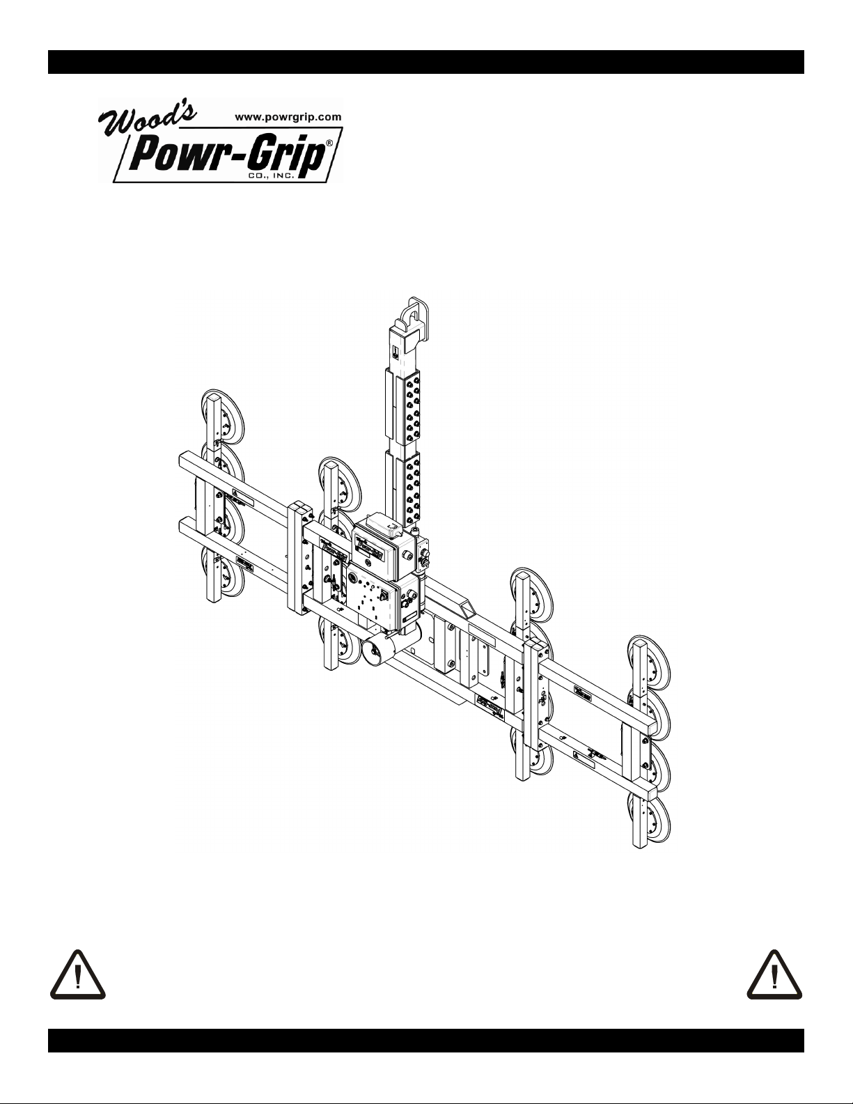
Rev 0.0/7-12 8 MR1611LDCO/DVS: #35048
INTENDED USE
LOAD CHARACTERISTICS
WARNING: This lifter is NOT intended for lifting hazardous materials, such as
explosives or radioactive substances.
The operator must verify that the lifter is intended to handle each load, in accordance with the
following requirements:
• The load must not exceed the maximum allowable weight specified under Load Capacity (see
SPECIFICATIONS).
• The load must be a single piece of nonporous or semiporous material with a flat and relatively
smooth contact surface.3To determine whether the load is too porous or rough, perform the
test under Vacuum Level on Other Surfaces (see OPERATION: TO APPLY THE PADS TO A LOAD).
• The load's contact surface must be suitable for obtaining a friction coefficient of 1 with the
lifter's vacuum pads (see MAINTENANCE: VACUUM PAD MAINTENANCE: Friction Coefficient), as
verified by a friction test. If necessary, contact Wood's Powr-Grip for help in conducting a
friction test.
• In order to avoid damaging the vacuum pads, the load's surface temperature must not exceed
the allowable Operating Temperatures (see SPECIFICATIONS). However, if such an
application cannot be avoided, Wood's Powr-Grip does offer a heat-resistant rubber
compound and other solutions which may enable you to lift loads with higher surface
temperatures. Contact Wood’s Powr-Grip or an authorized dealer for more information.
•While the
minimum
length and width of the load are determined by the Pad Spread (see
SPECIFICATIONS), the
maximum
length and width are determined by the allowable
overhang, or the amount of load material that can extend sideways beyond the vacuum pads
without breaking or otherwise being damaged.
The allowable overhang depends on the kind of load material being lifted, the thickness of the
material, and the angle at which it is handled (if any). Since materials such as glass, stone or
sheet metal each have different physical properties, the allowable overhang must be
evaluated separately for each type of load. If necessary, contact Wood’s Powr-Grip or an
authorized dealer for help in determining the recommended overhang in a specific situation.
• 1" [2.5 cm] is the maximum allowable thickness of loads at the maximum weight (see
SPECIFICATIONS: Load Capacity). However, allowable thickness increases as load weight
decreases. If necessary, contact Wood’s Powr-Grip for help in determining the maximum
thickness permitted when handling any specific load.
Note: Vacuum pads can stain or deform load surfaces with light colors or soft coatings. The
operator should test such surfaces for detrimental effects before using the lifter on them.
3Lifters that feature concave vacuum pads can also attach to some kinds of curved loads. Since curvature affects the lifting
capacity, contact Wood’s Powr-Grip for help in determining the Load Capacity for a particular curved load.

Rev 0.0/7-12 9 MR1611LDCO/DVS: #35048
OPERATING ENVIRONMENT
The operator must determine whether the lifter is intended to be used in each work environment,
in accordance with the following restrictions:
WARNING: Never use lifter in dangerous environments.
• This lifter is not intended for use in any environment that is inherently dangerous to the
operator or likely to compromise the lifter's ability to function. Environments containing
explosives, caustic chemicals and other dangerous substances must be avoided when using
the lifter.
• The lifter's work environment is limited by the Operating Elevation and Operating Temperatures
indicated in SPECIFICATIONS.
• The lifter's work environment must be free of metal particles or any other contaminates that
could damage lifter components through airborne contact or any other means of transmission
in the environment. If such contaminates cause a vacuum pump failure, they could result in a
load release and possible injury to the operator or others nearby.
WARNING: Environmental contaminates could result in vacuum pump failure.
• Using the lifter in wet environments may require the operator to take special precautions:
Moisture on contact surfaces of the load or vacuum pads diminishes the lifter’s slip resistance,
thereby reducing the lifting capacity (see MAINTENANCE: VACUUM PAD MAINTENANCE: Friction
Coefficient).
WARNING: Moisture reduces slip resistance of vacuum pads.
Although the lifter's exterior surfaces can tolerate some exposure to water vapor, they are not
designed to be water-tight. Submerging the lifter or using it in rain may damage lifter
components; these and similar conditions must be avoided.
DISPOSAL OF THE LIFTER
After the vacuum lifter has reached the end of its service life, you must dispose of the lifter in
compliance with all local codes and regulatory standards that are relevant for the geographical
region.
Note: This lifter is equipped with a battery, which may be subject to special disposal regulations.

Rev 0.0/7-12 10 MR1611LDCO/DVS: #35048
OPERATION
BEFORE USING THE LIFTER
The operator must determine whether the lifter is capable of performing each intended task, in
accordance with the SPECIFICATIONS and INTENDED USE sections of this
INSTRUCTIONS
manual. In addition, all of the following preparations must be completed prior to lifting any load.
Taking Safety Precautions
The operator must be trained in all relevant industry and regulatory standards for the operation
of the vacuum lifter in its geographical location (eg, ASME B30.20 in the USA).
The operator must read and understand this
INSTRUCTIONS
manual, including all
WARNINGS
,
before using the lifter. If necessary, contact Wood’s Powr-Grip or an authorized dealer for
assistance.
WARNING: Always wear appropriate personal protective equipment.
The operator must wear any personal protective equipment and take any other precautions
required to handle the load safely. Consult appropriate trade association guidelines to determine
what precautions are necessary for each type of load material.
Performing Inspections and Tests
WARNING: Always check battery energy before using lifter.
(See MAINTENANCE: BATTERY TEST)
Perform all inspections and tests required by the INSPECTION and TESTING
SCHEDULES (see MAINTENANCE). In addition, if the lifter has been in storage,
always conduct a VACUUM TEST before placing it in service (see MAINTENANCE).
The lifter is equipped with 3 air filters to help protect the vacuum generating system from
contaminants. In order for a filter to function, the operator must empty the filter bowl before
enough liquid accumulates to contact any portion of the filter element (see MAINTENANCE: AIR
FILTER MAINTENANCE).
WARNING: Examine each air filter regularly, and empty when necessary.
There are 2 small air filters located on the lifter's pad frame. If either of these filters is not
maintained properly, it could become obstructed, causing vacuum to build up in the line leading
to the large vacuum gauge and the vacuum lift light. Since the vacuum level at these vacuum
indicators would be higher than what actually exists elsewhere in the vacuum system, the lifter
could seem to be ready to lift the load, even though the lifter has not attained a vacuum level
sufficient for lifting the maximum load weight (see TO APPLY THE PADS TO A LOAD: Reading the
Vacuum Gauges and TO LIFT AND MOVE THE LOAD: Load Capacity and the Lift Light to follow). In
order to avoid this dangerous situation, each of the air filters must be maintained as directed in
the MAINTENANCE section.

Rev 0.0/7-12 11 MR1611LDCO/DVS: #35048
Confirming the Pad Frame Configuration
WARNING: Load Capacity of lifter varies, depending on pad frame configuration.
Make sure the pad frame has been assembled in the configuration that will provide optimal
support of the load while lifting (see ASSEMBLY: TO CHANGE THE PAD FRAME CONFIGURATION). The
pad frame configuration selected must be appropriate both for the weight and for the dimensions
of the load to be lifted.
TO APPLY THE PADS TO A LOAD
Powering up the Lifter
Place the lifter's power switch in the ON ( ) position.4The blue power light remains
illuminated while the lifter is powered up.
WARNING: Never turn power off while lifting.
Keep the power switch in the ON position while lifting a load. Any power interruption during a lift
could result in the release of a load and possible injury to the operator or others (see TO LIFT AND
MOVE THE LOAD: In Case of Power Failure to follow).
Positioning the Lifter on the Load
Make certain that the contact surfaces of the load and all vacuum pads are free of any
contaminates that could prevent the pads from sealing against the load (see MAINTENANCE:
VACUUM PAD MAINTENANCE).
The lifter must be attached only to vertically oriented loads. Center the pad frame to within 2" [5
cm] of the load center, since off-center loading can cause the load to rotate unexpectedly, and it
may also damage the lifter.5Make sure that all vacuum pads will fit entirely on the load’s contact
surface (see SPECIFICATIONS: Pad Spread) and that they will be loaded evenly while lifting (see
SPECIFICATIONS: Per-Pad Load Capacity). Then apply the lifter to the load so that all pads are
touching the contact surface.
Sealing the Pads against the Load
The apply/release switch is located on the movable control pendant. The movable control
pendant allows the vacuum controls to be moved away from the lifter, so that the operator can
control airflow at a distance equal to the length of the pendant cord.
WARNING: Do not disconnect control pendant during lifter operation.
4If a vacuum pump or any other powered component fails to function while the lifter's power switch is in the ON position,
examine each circuit breaker (adjacent to power switch) to determine whether it has interrupted the electrical circuit to the
component. Although the operator can reset the circuit breaker, the power interruption may indicate an electrical problem that
requires attention. Correct any deficiency before resuming normal operation of the lifter (see wiring diagram provided).
5The lifter is designed to handle the maximum load weight (see SPECIFICATIONS: Maximum Load Capacity) when the load’s
center of gravity is positioned within 2" [5 cm] of the pad frame’s center point. Occasional loading deviations are permissible,
provided that the operator can maintain control of the load at all times and that the load weight is low enough to avoid damaging
the lifter.

Rev 0.0/7-12 12 MR1611LDCO/DVS: #35048
The movable control pendant is not intended to be disconnected during lifter operation.
Disconnecting the control pendant is likely to result in a load release and injury to the operator or
others nearby.
Turn the apply/release switch on the movable control pendant to the “APPLY” position
(clockwise). This energizes the vacuum pumps, causing vacuum to be drawn immediately at the
vacuum pads. Press the lifter onto the load until all the pads seal against it. The apply/release
switch must remain in the “APPLY” position throughout the entire lift.
WARNING: Keep apply/release switch in “APPLY” position throughout lift.
Note: If a vacuum pad has been lying against a hard object (as during shipping), it may be
slightly distorted. Although initially it may be difficult to apply the pad to a load, this condition
should correct itself with continued use.
Reading the Vacuum Gauges
The lifter is equipped with 3 vacuum gauges: 2
small
vacuum gauges are located on the pad
frame, to indicate the current vacuum level in each circuit of the lifter's vacuum system. A third,
large
vacuum gauge is located on the lift bar. So long as the air filters on the pad frame are
maintained properly (see BEFORE USING THE LIFTER: Performing Inspections and Tests preceding),
the large vacuum gauge indicates the lower of the vacuum levels existing in the 2 circuits.
Each vacuum gauge registers vacuum in the same way: The
green
range indicates vacuum
levels sufficient for lifting the maximum load weight, whereas the
red
range indicates vacuum
levels that are
not
sufficient for lifting the maximum load weight. The gauge needle should
show a sudden surge in vacuum as the vacuum pads seal against the load. If it takes more than
5 seconds for the vacuum level to reach 5" Hg [-17 kPa] on a vacuum gauge, press on any pad
that has not yet sealed.

Rev 0.0/7-12 13 MR1611LDCO/DVS: #35048
Vacuum Level on Optimal Surfaces
When the lifter is attached to clean, smooth, nonporous load surfaces, it should be able to
maintain a vacuum level in the green range on all 3 vacuum gauges, except when used at high
elevations (see SPECIFICATIONS: Operating Elevation). If not, make sure the vacuum switch is
adjusted correctly (see MAINTENANCE: VACUUM SWITCH ADJUSTMENT). If the vacuum switch
cannot be adjusted to maintain a vacuum of 16" Hg [-54 kPa], perform the VACUUM TEST (see
MAINTENANCE) to determine whether there is a deficiency in the vacuum generating system.
Vacuum Level on Other Surfaces
When the lifter is attached to contaminated, rough or porous load surfaces, it may not be able to
maintain a vacuum level in the green range on all 3 vacuum gauges, due to leakage in the seal
between the vacuum pads and the load surface.6In the case of contamination, thoroughly clean
the contact surfaces of the load and the vacuum pads (see MAINTENANCE: VACUUM PAD
MAINTENANCE: Cleaning), and reapply the lifter to the load. If the load has rough or porous
surfaces,
the operator must conduct a test to determine whether the lifter is designed
to lift the load
, as follows:
1) Make sure the lifter's vacuum generating system is functioning correctly (see MAINTENANCE:
VACUUM TEST).
2) Apply the vacuum pads to the load as previously directed.
3) After the vacuum pumps stop running, place the power switch in the OFF ( ) position.
4) Raise the load a minimal distance, to assure that it is supported by the lifter.
5) Monitor the large vacuum gauge while the load is suspended for 5 minutes:
The lifter must
maintain a minimum vacuum level of 10" Hg [-34 kPa] during this time.
If not, the
load does not possess the characteristics required for using this lifter.7
TO LIFT AND MOVE THE LOAD
WARNING: Never attempt to lift load when lifter is in horizontal
orientation.
Load Capacity and the Lift Light
A lifter’s Load Capacity is rated at a vacuum level of 16" Hg [-54 kPa] (see SPECIFICATIONS).
After the lifter has attained this level, the vacuum pumps turn off automatically, to conserve
battery energy. At the same time, the green vacuum lift light turns on, to indicate that the lifter
is ready to lift the maximum load weight.
WARNING: Never attempt to lift load unless green lift light is illuminated.
Do not attempt to lift the load unless the lift light is illuminated; such an attempt could result in a
load release and possible injury to the operator.
6Contaminated loads can also cause the vacuum pumps to run frequently or continuously. Since excessive pumping quickly
reduces battery energy, the operator should clean the load when possible, to minimize pumping.
7Certain load materials are too rough or porous to allow the lifter to form a seal which can be maintained for 5 minutes without
power. However, in geographical locations where CE Standards do not apply, it may be possible to use the lifter to lift such loads.
Contact Wood’s Powr-Grip for more information.

Rev 0.0/7-12 14 MR1611LDCO/DVS: #35048
Monitoring Vacuum Indicators
The vacuum lift light and the large vacuum gauge must remain completely visible to the
operator, so that they can be monitored throughout the entire lift.8
WARNING: Vacuum indicators must be visible to operator throughout entire lift.
If the vacuum system experiences leakage while the lifter is attached to the load, the vacuum
pumps turn
on
automatically, as required to maintain sufficient vacuum for lifting the maximum
load weight. The lift light turns
off
while the pumps are running, to signal the reduction in
vacuum to the operator.
If the pumps turn on and the lift light turns off while you are lifting a load, make sure the large
vacuum gauge shows a vacuum level of 16" Hg [-54 kPa] or higher. If not, move away and stay
clear of the load until it can be lowered to the ground or a stable support.
WARNING: Stay clear of any suspended load while vacuum level is lower than
16" Hg [-54 kPa].
Discontinue lifter use until the cause of the vacuum loss can be determined. If the pumps run at
intervals of ten minutes or less while the lifter is attached to clean, smooth, nonporous materials,
the leakage is likely to be in the vacuum system. In this event, perform the VACUUM TEST (see
MAINTENANCE) and inspect the vacuum pads for damage (see MAINTENANCE: VACUUM PAD
MAINTENANCE: Inspection). If the vacuum loss cannot be remedied immediately, perform
inspection and maintenance as needed to identify and correct any deficiency before resuming
normal operation of the lifter.
Controlling the Lifter and Load
When vacuum indicators show that the lifter is ready, use the hoisting equipment to raise the
lifter and load as needed to clear any obstacles in their path. Use any appropriate means to keep
the lifter and load in the desired orientation while they are suspended from the crane. Once
sufficient clearance is established, the load can be rotated as desired (see TO ROTATE THE LOAD
EDGEWISE to follow).
In Case of Power Failure
The lifter is equipped with 3 vacuum reserve tanks, designed to maintain vacuum temporarily in
case of a failure at the lifter's power source.
WARNING: Stay clear of any suspended load in the event of a power failure.
Although the lifter is designed to support the load for at least 5 minutes without power, this
depends on many factors, including the condition of the load and the lifter’s vacuum system (see
INTENDED USE: LOAD CHARACTERISTICS and MAINTENANCE: VACUUM PAD MAINTENANCE,VACUUM
TEST). If a power failure occurs, keep all personnel clear of the suspended load until it can safely
be placed on the ground or a stable support. Correct any deficiency before resuming normal
operation of the lifter.
8In addition, the small vacuum gauges mounted on the pad frame can be used to monitor the status of each circuit of the
vacuum system (see TO APPLY THE PADS TO A LOAD: Reading the Vacuum Gauges preceding).

Rev 0.0/7-12 15 MR1611LDCO/DVS: #35048
TO ROTATE THE LOAD EDGEWISE
WARNING: Make sure load is positioned correctly on lifter (see TO APPLY);
unbalanced loads may rotate unexpectedly when latch is
disengaged.
Remember that the load is longer in its diagonal dimensions than in its side
dimensions; raise the load high enough to clear any obstacles when
rotating. Keep the load under control at all times, using hand cups or other
appropriate means. Disengaging the pad frame's rotation latch allows the
load to rotate. Pull the cable that hangs from the rotation release lever to
disengage the rotation latch, and rotate the load to the desired position.
To stop the load's motion automatically at each quarter turn, simply let go of
the cable immediately after initiating the rotation, so that the rotation latch
engages at the next stop. Whenever rotation is not required, keep the
rotation latch engaged, to prevent accidental damage to the load and
possible injury to the operator.
TO RELEASE THE PADS FROM THE LOAD
WARNING: Load must be fully supported before releasing vacuum pads.
Make sure the load is at rest and fully supported. As a safety precaution, two actions must be
performed to release the pads from the load: The vacuum lift light also functions as a push-
button switch. Press and hold this vacuum control push button throughout the release operation.
At the same time, turn the apply/release switch to the “RELEASE” position (counter-clockwise) to
force air into the vacuum pads, quickly breaking the vacuum seal. Continue to hold the
apply/release switch and the push-button switch until the pads disengage completely from the
load.9
When the apply/release switch is no longer held in the “RELEASE” position, it automatically
returns to the neutral position. Do not turn the apply/release switch to the “APPLY” position until
the pads are contacting the next load to be lifted. This conserves battery energy and reduces
the time required to apply the pads to the load, by preventing the primary vacuum reserve tank
from losing its vacuum.
9If the pads do not release fully or they release too slowly, make sure the release mechanism is functioning correctly (see
MAINTENANCE: VACUUM TEST: Release Function Test).

Rev 0.0/7-12 16 MR1611LDCO/DVS: #35048
AFTER USING THE LIFTER
Leave the apply/release switch in the neutral position and place the power switch in the OFF
position ( ).
CAUTION: Do not set the lifter against any surfaces which could soil or damage the
vacuum pads.
Built-in parking feet can be used to support an unloaded lifter when not suspended from a crane:
Make sure the pad frame is oriented vertically with the parking feet at the bottom. Use the
hoisting equipment to gently lower the lifter until the parking feet support its entire weight.
Make sure the lifter leans securely against an appropriate support; then detach the hoisting
equipment hook from the lift bail.
If the lifter is transported to another location, use the original shipping container and secure the
lifter so as to protect the vacuum pads and all other components from damage while in transit.
Storing the Lifter
Use the covers supplied to keep the vacuum pads clean.
!!-CE-!! In accordance with CE Standard EN 13155, the lifter is designed to rest on relatively
horizontal surfaces without tipping over. To store the lifter in this way, set the lifter with the
pads facing downward on a clean, smooth, flat surface and place a support under the lift bail.
Since the lifter’s intended use does not include tilting, be careful to protect the vacuum pads and
support the lifter while tilting it to the horizontal position.
Charge the battery completely when placing it in storage and at six-month intervals thereafter
(see MAINTENANCE: BATTERY RECHARGE). After charging the battery, disconnect the electrical
connectors uniting the battery to the battery charger and to the vacuum generating system, in
order to prevent power drainage. Preferred temperatures for storing the battery are 32° to 70°
Fahrenheit [0° to 21° Celsius]. Higher temperatures require the battery to be charged more
frequently. Storage at temperatures above 100° Fahrenheit [38° Celsius] should be avoided.

Rev 0.0/7-12 17 MR1611LDCO/DVS: #35048
MAINTENANCE
WARNING: Always make sure battery is disconnected before servicing lifter.
INSPECTION SCHEDULE
Perform inspections routinely, according to the following frequency schedule:
Every-Lift Inspection
• Examine the vacuum pads and load surface for contamination or debris (see VACUUM PAD
MAINTENANCE to follow).
• Examine the vacuum pads, controls and indicators for visual damage (see VACUUM PAD
MAINTENANCE to follow).
• Test the battery for adequate charge (see BATTERY TEST to follow).
If a battery’s charge appears to be inadequate, charge and retest the battery (see BATTERY
RECHARGE to follow). If any other deficiency is detected during the inspection, correct it before
using the lifter and perform the Frequent Inspection to follow.
Frequent Inspection
(
following every 20-40 hours’ use; or whenever lifter is out of service for 1 month or more
)
• Examine the lifter’s structure for visual damage.
• Examine the vacuum system (including vacuum pads, fittings and hoses) for visual damage.
• Examine the air filter for conditions requiring service (see AIR FILTER MAINTENANCE to follow).
• Perform the VACUUM TEST to follow.
• Check for unusual vibrations or noises while operating the lifter.
If any deficiency is detected during the inspection, correct it before using the lifter and perform
the Periodic Inspection to follow.
Periodic Inspection
(
following every 250-500 hours’ use; or whenever lifter is out of service for 1 year or more
)
• Examine the entire lifter for external evidence of looseness, excessive wear, deformation,
cracks, excessive corrosion, dents to structural or functional components, cuts, or any
deficiency which might constitute a hazard.
• Inspect all parts of the electrical system for damage, wear or contamination that could
constitute a hazard, in compliance with all local codes and regulatory standards that are
relevant for the geographical region.
CAUTION: Be sure to use appropriate cleaning methods for each type of electrical
component, as specified by codes and standards. Improper cleaning
can damage components.
• Keep a written record of all Periodic Inspections.

Rev 0.0/7-12 18 MR1611LDCO/DVS: #35048
If any deficiency is detected during the inspection, correct it before using the lifter. If necessary,
return the lifter to Wood’s Powr-Grip or an authorized dealer for repair (see LIMITED
WARRANTY).
Infrequent Use
If a lifter is used less than 1 day in a 2-week period, perform the Periodic Inspection
each time
before using the lifter
.
TESTING SCHEDULE
Perform these tests when placing the lifter in service
initially
and
each time following a repair or
modification
. Correct any deficiency and retest before using the lifter.
Operational Tests
• Perform the VACUUM TEST to follow.
• Test all features and functions of the lifter (see OPERATING FEATURES, OPERATION and
MAINTENANCE).
Load Test
Prove that the lifter can lift 100% of its Maximum Load Capacity (see SPECIFICATIONS), using an
actual load or an equivalent simulation.10 Employ the following method to test with an actual
load:
1) Place a test load with appropriate LOAD CHARACTERISTICS (see INTENDED USE) on a stable
support. Make sure the load is oriented in the upright position.11
2) Apply the vacuum pads to the load as previously directed.
3) After the vacuum pump stops running, place the power switch in the OFF ( ) position.
4) Raise the load a minimal distance, to assure that it is supported by the lifter.
5) Hold the load for 5 minutes. The load must not slip or fall during this time period. If it does,
conduct a VACUUM TEST and inspect each vacuum pad as indicated under VACUUM PAD
MAINTENANCE: Inspection (see sections to follow). Correct any deficiency that is found and
retest the lifter.
Note: See MAINTENANCE topics to follow for additional directions about inspecting and testing
specific lifter components.
MAINTENANCE SCHEDULE
Unless specified elsewhere in this
INSTRUCTIONS
manual, the lifter does not require
maintenance on a routine basis. Instead, maintenance must be performed whenever a
deficiency is indicated by routine inspections or tests. Any maintenance warranted must be
performed before resuming normal operation of the lifter.
10 ASME Standard B30.20 requires the lifter to be tested to 125% of its Load Capacity.
11 Flat Lifters are exempt from this requirement.
This manual suits for next models
1
Table of contents
Other WOOD'S POWR-GRIP Industrial Equipment manuals
Popular Industrial Equipment manuals by other brands

SPX
SPX Marley Geareducer 34.4 Series user manual

Parker
Parker 732 Series owner's manual

Fire Pants Fabrication
Fire Pants Fabrication Kelpie V1.2 Setup instructions

Youngman
Youngman Lightweight Staging 33050800 instruction manual

ABB
ABB HT612294 Operation manual

Baileigh Industrial
Baileigh Industrial SR-5016E Operator's manual