WOOD'S POWR-GRIP MRTALPCH611LDC User manual

KEEP FOR FUTURE REFERENCE
INSTRUCTIONS
International Version
MODEL NUMBERS: MRTALPCH611LDC,
MRTALPCH6HV11DC, MRTALPCH610DCO
SERIAL NUMBER: ___________
(please see serial label and record number here)
MANUAL ROTATOR / TILTER
LOW-PROFILE, DC-VOLTAGE
WITH DUAL VACUUM SYSTEM
AND CHANNEL-STYLE PAD FRAME
READ ALL INSTRUCTIONS AND WARNINGS
BEFORE OPERATING THIS LIFTER
DESIGNED FOR MATERIALS-HANDLING PROFESSIONALS
P.O. Box 368 –908 West Main
Laurel, MT USA 59044
phone 800-548-7341
phone 406-628-8231
fax 406-628-8354


Rev 13.0/5-19 1 MRTALPCH6-DC: #35054
TABLE OF CONTENTS
SPECIFICATIONS............................................................................................................ 3
WARNINGS ..................................................................................................................... 4
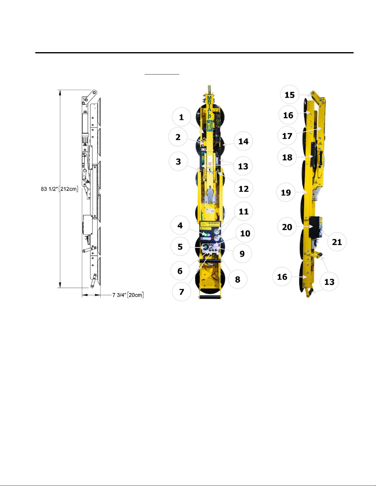
OPERATING FEATURES................................................................................................... 5
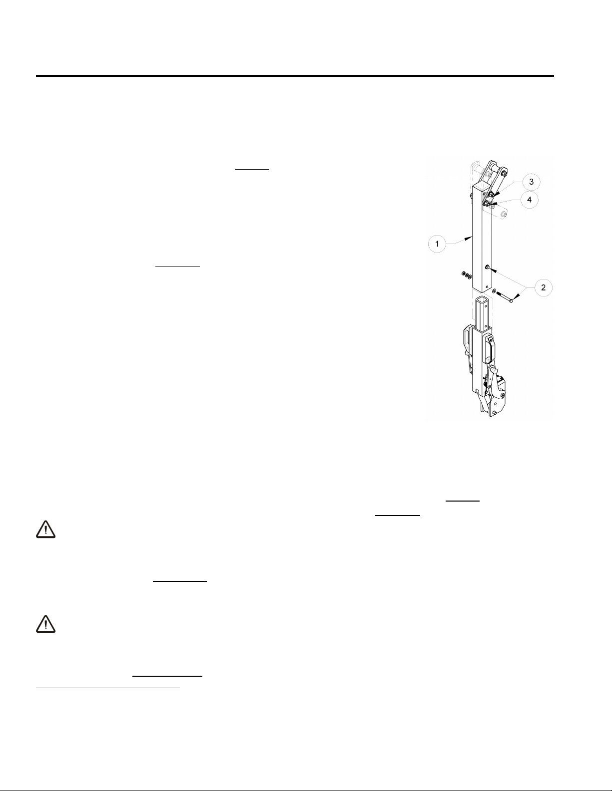
ASSEMBLY....................................................................................................................... 6
TO SET UP THE LIFTER ................................................................................................................6
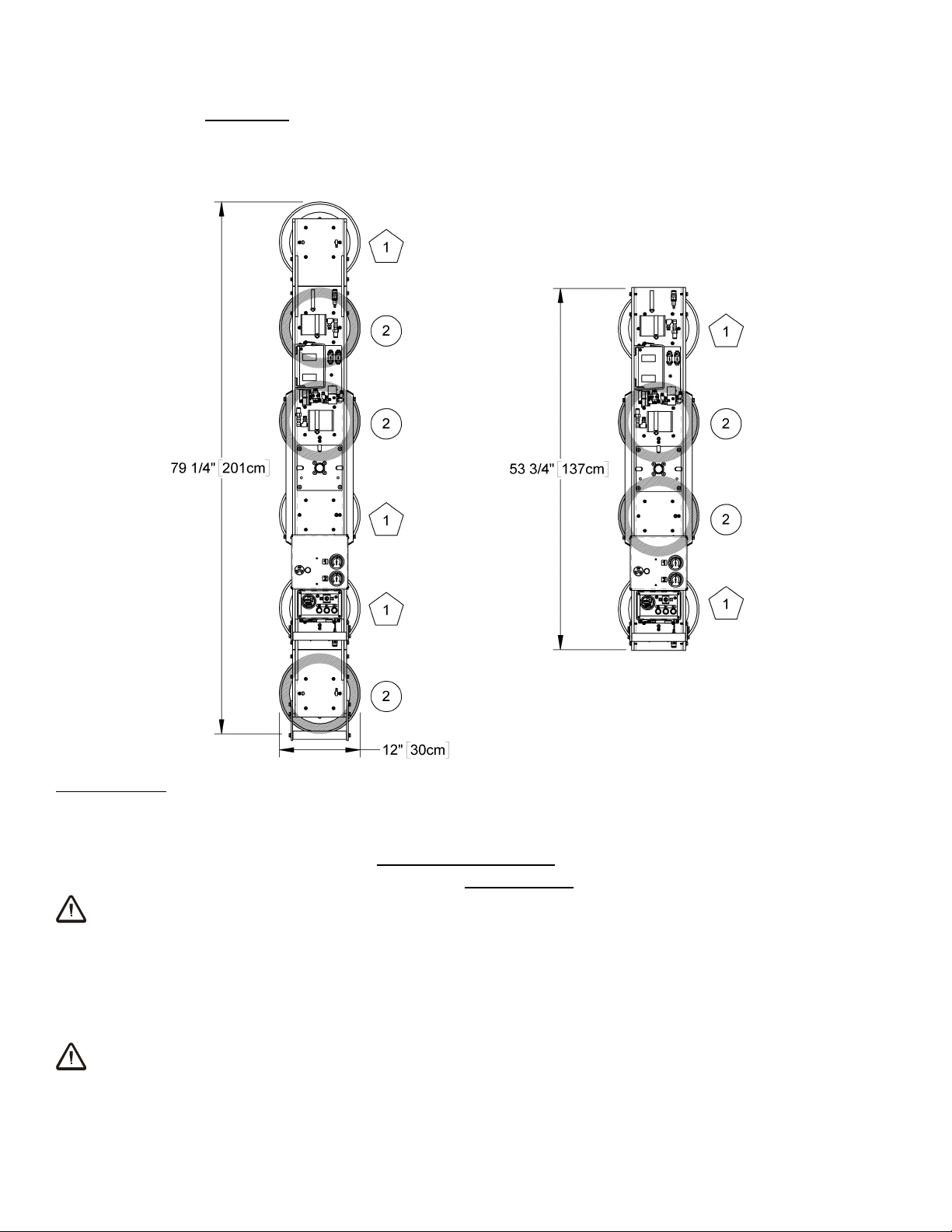
TO CHANGE THE PAD FRAME CONFIGURATION ................................................................................8
To Install/Remove Pad Frame Extensions ......................................................................................................9
To Connect/Disconnect Vacuum Hoses..........................................................................................................9
To Route Vacuum Hoses ............................................................................................................................10
INTENDED USE ............................................................................................................. 11
LOAD CHARACTERISTICS ........................................................................................................... 11
OPERATING ENVIRONMENT .......................................................................................................12
DISPOSAL OF THE LIFTER ..........................................................................................................13
OPERATION .................................................................................................................. 14
BEFORE USING THE LIFTER........................................................................................................14
Taking Safety Precautions ..........................................................................................................................14
Performing Inspections and Tests ...............................................................................................................14
Confirming the Pad Frame Configuration .....................................................................................................15
Preparing to Use the Optional Remote Control System .................................................................................15
TO ATTACH THE PADS TO A LOAD................................................................................................16
Positioning the Lifter on the Load ...............................................................................................................16
Powering up the Lifter................................................................................................................................16
Reading the Vacuum Gauges ......................................................................................................................17
Vacuum Level on Optimal Surfaces .............................................................................................................17
TO LIFT AND MOVE THE LOAD ....................................................................................................19
Positioning the Lift Bar ...............................................................................................................................19
Interpreting the Warning Buzzer and Lift Light ............................................................................................19
Monitoring Vacuum Indicators ....................................................................................................................19
Monitoring the Low Vacuum Warning Buzzer ...............................................................................................20
Controlling the Lifter and Load....................................................................................................................20
In Case of Power Failure ............................................................................................................................20
TO ROTATE THE LOAD EDGEWISE................................................................................................21
TO TILT THE LOAD ...................................................................................................................22
TO RELEASE THE PADS FROM THE LOAD .......................................................................................22
AFTER USING THE LIFTER..........................................................................................................23
Storing the Lifter........................................................................................................................................23
MAINTENANCE.............................................................................................................. 24
INSPECTION SCHEDULE.............................................................................................................24
Every-Lift Inspection ..................................................................................................................................24
Frequent Inspection ...................................................................................................................................24

Rev 13.0/5-19 2 MRTALPCH6-DC: #35054
Periodic Inspection.....................................................................................................................................24
Infrequent Use...........................................................................................................................................25
TESTING SCHEDULE..................................................................................................................25
Operational Tests.......................................................................................................................................25
Load Test ..................................................................................................................................................25
MAINTENANCE SCHEDULE..........................................................................................................26
BATTERY TEST .........................................................................................................................26
BATTERY RECHARGE .................................................................................................................26
BATTERY CHARGER TEST ...........................................................................................................27
VACUUM PAD MAINTENANCE......................................................................................................27
Friction Coefficient .....................................................................................................................................27
Inspection .................................................................................................................................................28
Cleaning ....................................................................................................................................................28
VACUUM TEST .........................................................................................................................29
REMOTE CONTROL SYSTEM TEST ................................................................................................29
AIR FILTER MAINTENANCE ........................................................................................................30
Filter Function and Conditions Requiring Service ..........................................................................................30
Filter Service Procedures ............................................................................................................................30
VACUUM PUMP MAINTENANCE −DYNAFLO DV1032102 ...............................................................31
Replacing the Diaphragm ...........................................................................................................................31
Replacing the Head Assembly .....................................................................................................................31
VACUUM PUMP MAINTENANCE −THOMAS 107CDC20 ..................................................................32
Replacing the Diaphragm ...........................................................................................................................32
Replacing the Intake Valve Flapper .............................................................................................................32
Replacing the Exhaust Valve Flapper and Head Gasket .................................................................................32
VACUUM SWITCH ADJUSTMENT ..................................................................................................33
Vacuum Switch Function ............................................................................................................................33
Adjustment Procedure ................................................................................................................................33
REPLACEMENT PARTS LIST .......................................................................................... 34
LIMITED WARRANTY.................................................................................................... 36

Rev 13.0/5-19 3 MRTALPCH6-DC: #35054
SPECIFICATIONS
Description:
Designed for use with a crane or other hoisting equipment, MRTALPCH6-DC lifters employ vacuum to hold
a load for lifting, and they provide manual 180° rotation and manual 90° tilt movements for load
manipulation.
Model Number:
MRTALPCH611LDC
MRTALPCH6HV11DCO
MRTALPCH610DCO
Vacuum Pads:1
(Six of standard rubber, spring-mounted with 1/8" [3 mm] travel and #60 filter screen)
11" [28 cm] nom. diameter,
lipped (Model G3370)
10" [25 cm] nom. diameter,
lipped (Model HV11)
10" [25 cm] nom. diameter,
concave (Model G0750)
Pad Spread:
(to outer edges)
Minimum:
53¾" x 12" [1,365 x 305 mm]
52¾" x 11" [1,340 x 279 mm]
51¾" x 10" [1,314 x 254 mm]
Maximum:
79¼" x 12" [2,010 x 305 mm]
78¼" x 11" [1,988 x 279 mm]
77¼" x 10" [1,962 x 254 mm]
Maximum Load Capacity:2
Per-Pad:
184 lbs [83.5 kg]
150 lbs [68.5 kg]
150 lbs [68.5 kg]
With 4 pads:
700 lbs [320 kg]
600 lbs [270 kg]
600 lbs [270 kg]
With 6 pads:
1,100 lbs [500 kg]
900 lbs [410 kg]
900 lbs [410 kg]
Lifter Weight:
130 lbs [59 kg]
Power Source:
12 volts DC, 10 amps (with Thomas pump) or 3 amps (with Dynaflo pump)
Battery Capacity:
7 amp-hours
Tilt Capability:
Manual, 90°, with mechanical advantage that minimizes operator effort and automatic latching in upright
position
Rotation Capability:
Manual, 180°, with automatic latching at each ¼ revolution
Vacuum Pump:
Diaphragm type, 1 SCFM [28 liters/minute] nominal airflow
Dual Vacuum System:
2 vacuum system circuits allow the lifter to maintain the vacuum level in one circuit even if an unexpected
vacuum loss occurs in the other one (eg, due to load breakage).
Vacuum Gauges:
2 dial gauges indicate current vacuum level in positive inches of Hg and negative kPa.
Vacuum Lift Light:
Green light turns on whenever vacuum is higher than the level required to lift the maximum load weight
(18 Hg [-60 kPa]).
Low Vacuum Warning Buzzer: Maximum Volume = 103 dBA at 2' [60 cm]. While the lifter is powered up, an audible alarm warns the
operator whenever vacuum is not sufficient for lifting the maximum load weight.
Options:
Available
with Remote Control System. This option features a radio transmitter that can activate “attach”
and “release”functions at distances up to 250' [76 m]. The system uses a 310-320 MHz signal.
See separate instructions about other optional features.
Operating Elevation:
Maximum = 4,500' [1,370 m]
Operating Temperatures:
32° to 104° F [0° to 40° C]
Service Life:
This lifter is designed to have a service life of 20,000 lifting cycles, when used and maintained as intended.
Vacuum pads, filter elements and other wear-out items are excluded; see MAINTENANCE and REPLACEMENT
PARTS LIST for more information. For the D
ISPOSAL OF THE
L
IFTER
after its service life, see INTENDED USE.
ASME Standard BTH-1:
Design Category "B", Service Class "0" (see www.wpg.com for more information)
!!‒CE‒!! Note: This symbol appears only when a CE Standard is
different
from requirements of other applicable standards. CE requirements are
mandatory in the European Union, but may be optional elsewhere.
1
Optionally available with alternative rubber compounds for special applications (see REPLACEMENTS PARTS LIST).
2
The Maximum Load Capacity is rated at a vacuum of 18 Hg [-60 kPa] on clean, smooth, nonporous flat surfaces with a friction coefficient of 1.
Pad compound, load rigidity, strength, surface conditions, overhang, angle, center of gravity and temperature can also affect the lifting capacity.
A qualified person should evaluate the effective lifting capacity for each use.

Rev 13.0/5-19 4 MRTALPCH6-DC: #35054
WARNINGS
Powr-Grip is pleased to offer the most reliable vacuum lifters available.
Despite the high degree of security provided by this product, certain
precautions must be observed to protect the operator and others.
Always
wear personal protective equipment that is appropriate for the material being handled.
Follow trade association guidelines.
Always
operate the lifter under conditions approved for its design (see INTENDED USE:
OPERATING ENVIRONMENT).
Never
operate a lifter that is damaged, malfunctioning, or missing parts.
Never
operate a lifter if the sealing edge of any vacuum pad is cut or otherwise damaged.
Never
remove or obscure warning labels.
Never
operate a lifter if the Maximum Load Capacity or any warning appears to be missing or
obscured.
Always
make certain the contact surfaces of the load and all vacuum pads are clean prior to
attaching the pads (see MAINTENANCE: VACUUM PAD MAINTENANCE).
Never
exceed the Maximum Load Capacity or attempt to lift loads the lifter is not designed for
(see INTENDED USE: LOAD CHARACTERISTICS).
Never
attempt to lift cracked or broken glass with this lifter.
Always
position the vacuum pads correctly on the load prior to lifting (see OPERATION: TO
ATTACH THE PADS TO A LOAD).
Never
lift a load when any vacuum indicator shows inadequate vacuum.
Never
touch the vacuum release controls during a lift. This may result in loss of vacuum and
release of the load.
Never
allow people to ride on the lifter or the load being lifted.
Never
lift a load higher than necessary or leave suspended loads unattended.
Never
lift a load over people.
Always
keep other personnel far enough away from the lifter to avoid injury in the event of an
unexpected load release.
Always
place the power control in the inactive position and, when possible, disconnect the
power source before opening any enclosure on the lifter. (Only applicable to powered lifters)
Always
remember that modifications to the lifter could compromise its safety. Wood’s Powr-
Grip cannot be responsible for the safety of a lifter that has been modified by the customer.
For consultation, contact Wood's Powr-Grip (see LIMITED WARRANTY).
Never
disengage both the rotation latch and the tilt latch at the same time.
If the lifter is equipped with a Remote Control System,
never
operate the lifter remotely unless
there is clear communication about intended actions (eg, releasing a load) with all personnel
near the lift. In addition, the operator must visually verify the status of the lifter and load
prior to remote operations.

Rev 13.0/5-19 5 MRTALPCH6-DC: #35054
OPERATING FEATURES
Note: Components featured in the following instructions for assembling, operating or maintaining
the vacuum lifter are underlined on their first appearance in each section.
Standard MRTALPCH611LDC shown
1 BATTERY CHARGER
10 BATTERY TEST BUTTON
18 Cover for BATTERY
2 VACUUM RESERVE TANKS
11 VACUUM GAUGES
19 PAD FRAME
3 TILT RELEASE LEVER
12 ROTATION RELEASE LEVER
20 Cover for VACUUM PUMP and
4 VACUUM LIFT LIGHT
13 CONTROL HANDLES
VACUUM SWITCH
5 BATTERY GAUGE
14 VACUUM PAD
21 LOW VACUUM WARNING BUZZER
6 “FUNCTION” BUTTON
15 LIFT SPOOL
Not shown: QUICK CONNECTORS
7 “ATTACH” BUTTON
16 PAD FRAME EXTENSION
AIR FILTERS, STROBE LIGHT (optional)
8 “RELEASE” BUTTON
17 LIFT BAR
and RADIO RECEIVER (optional)
9 POWER SWITCH

Rev 13.0/5-19 6 MRTALPCH6-DC: #35054
ASSEMBLY
TO SET UP THE LIFTER
1) Open the shipping container and remove all materials for restraining or protecting the vacuum
lifter. Save the container for use whenever the lifter is transported.
2) If necessary, assemble the lifter's lift bar as follows: One segment
of the lift bar can be removed, to reduce overall lifter dimensions
for shipping. If so, orient the removable segment (1) as shown in
the illustration, and slide it over the other segment until the bolt
holes align. Reinstall the bolts and all associated hardware (2); then
tighten both bolts securely.
3) Position the lifter's lift spool as follows: The adjustable lift spool
assembly provides 3 different lift points (see illustration), in order to
optimize the lifter's hang angle and/or its overall height for the
intended use.
3
To change the lift spool position, remove the
retaining bolt (3) and, if necessary, loosen the pivot bolt (4). Next
pivot the lift spool assembly until the bolt holes align for the desired
spool position. Then reinstall the retaining bolt and all associated
hardware. Tighten both bolts securely.
4) Suspend the lifter from a crane as follows: Select hoisting
equipment (crane and hoist, when applicable) rated to carry the
maximum load weight plus the lifter weight (see SPECIFICATIONS:
Maximum Load Capacity and Lifter Weight).
Note: Any application of the lifter must conform to all statutory or regulatory standards that
relate to the hoisting equipment when used in its geographical location (eg, relevant OSHA
standards in the USA).
Disengage the tilt latch (see OPERATION: TO TILT THE LOAD) and raise the lift bar to a vertical
orientation. Then attach the hoisting equipment hook to the lift spool.
WARNING: Hoisting equipment hook must be fitted with restraining latch to
prevent lift spool from slipping off under any circumstances.
Note: Some hoisting equipment hooks could interfere with an upright load that extends
beyond the lifter's pad frame. If the load would contact the hook during lifter operation, the
operator must prevent this by attaching a sling (or other rigging that does not interfere with
the load) between the hook and the lift spool.
WARNING: Any sling used must be rated to carry maximum load weight plus
lifter weight.
Use the hoisting equipment to raise the lifter out of the shipping container. Be careful to avoid
damaging any vacuum pads.
3
When the pad frame is used in the vertical orientation (see illustration in OPERATING FEATURES), placing the lift spool in the
lowest position creates interference with the pad frame extension. To avoid this problem, place the lift spool in one of the other
two positions or remove the pad frame extensions (see TO CHANGE THE PAD FRAME CONFIGURATION to follow).

Rev 13.0/5-19 7 MRTALPCH6-DC: #35054
5) Arrange the pad frame in the configuration that will provide optimal support of the load while
lifting (see TO CHANGE THE PAD FRAME CONFIGURATION to follow). Remove the pad covers and
save them for use whenever the lifter is stored.
6) Connect the electrical connectors uniting the battery to the battery charger and the vacuum
generating system. Now the lifter is operational.
7) Perform Operational and Load Tests for the lifter as directed in MAINTENANCE: TESTING
SCHEDULE. If the lifter is equipped with a Remote Control System, also perform the REMOTE
CONTROL SYSTEM TEST (see MAINTENANCE).

Rev 13.0/5-19 8 MRTALPCH6-DC: #35054
TO CHANGE THE PAD FRAME CONFIGURATION
The lifter offers 2 pad frame configurations to accommodate different load dimensions and
weights (see SPECIFICATIONS: Pad Spread and Maximum Load Capacity). Select the
configuration that provides optimal support across the load surface and minimizes load overhang
(see OPERATION: BEFORE USING THE LIFTER).
Vacuum pads corresponding with the 2 circuits of the dual vacuum system are marked “1” and
“2” in the illustration above (see To Route Vacuum Hoses to follow). The distribution of pads is
designed to optimize load support for each circuit.
To support longer, heavier loads, both pad frame extensions must be installed on the pad frame
and the vacuum hoses must be connected to the vacuum pads located on the extensions.
WARNING: Removing any extension or disconnecting the corresponding vacuum
pad reduces load capacity of lifter.
To support smaller dimensions and weights, the pad frame extensions may be removed, and the
corresponding vacuum hoses may be disconnected,
provided that the lifter still has
sufficient capacity to support the load in question
(see INTENDED USE: LOAD
CHARACTERISTICS). The Load Capacity is reduced when the pad frame extensions are removed.
WARNING: Either install both extensions or remove both.
Always assemble the pad frame with both extensions installed or both removed, to keep the lifter
balanced.

Rev 13.0/5-19 9 MRTALPCH6-DC: #35054
To Install/Remove Pad Frame Extensions
4
1) Set the lifter with the vacuum pads facing downward on a clean, smooth, flat surface.
2) To install pad frame extensions, insert the tabs extending from one pad frame extension
between the rails of the pad frame. If the tabs do not fit between the rails, loosen the bolts
that connect the tabs to the extension. Make sure the vacuum pads on the extension and on
the pad frame are contacting the same surface, so all the pads are aligned in the same plane.
Note: The pad frame extension that is equipped with a control handle should be installed on
the lower end of the pad frame (ie, when oriented vertically).
3) Align the bolt holes in the pad frame extension with the bolt holes in the pad frame.
4) Secure the pad frame extension in the pad frame by installing and tightening all bolts
securely.
5) Connect the vacuum hose to the vacuum pad on the pad frame extension, as directed in To
Connect/Disconnect Vacuum Hoses.
6) Repeat steps 2-5 to install the other pad frame extension.
7) To remove pad frame extensions, reverse steps 2-6. Store removed extensions in a clean, dry
location. Use the pad covers supplied to keep the vacuum pads clean.
To Connect/Disconnect Vacuum Hoses
Hoses for 4 of the lifter’s vacuum pads are connected to or
disconnected from the vacuum system by means of quick
connectors. To connect a vacuum hose, push the male and
female ends of the connector together until they lock. To
disconnect, move the release ring on the female end away from
the male end until the connector separates.
WARNING: Make sure vacuum hoses are routed and
secured as needed to prevent them
from being damaged during lifter operation.
Make sure all vacuum hoses are routed and secured as needed to avoid being punctured,
pinched, kinked, entangled, abraded or otherwise damaged while the lifter is in operation.
Note: Whenever a quick connector is disconnected, the corresponding vacuum pad does not
contribute to the load capacity, whether or not the extension is installed on the pad frame.
4
The lifter ships with the pad frame extensions already installed on the pad frame. The extensions do not need to be removed
when using the 4-pad configuration unless they would inhibit (or otherwise compromise safety of) loading, positioning a load or
releasing a load.
QUICK CONNECTOR
1 FEMALE END
2 MALE END

Rev 13.0/5-19 10 MRTALPCH6-DC: #35054
To Route Vacuum Hoses
Each of the two pad frame configurations requires specific routing for vacuum hoses
connecting to the vacuum pads via two quick connectors on each end of the pad frame.
Labels attached to each of the blue hoses near the male end of their quick connectors provide
assistance for making the correct circuit connection in either configuration.
For the 6-pad configuration:
1) Connect the 2 hoses leading from the 2 vacuum pads on
the pad frame extensions to the circuits nearest to the
base of pad frame.
Note: When connected correctly, the color of the hoses
at both the male and female ends of the quick connector
will match (green for circuit “1” and red for circuit “2”).
2) Connect the 2 blue hoses to the other circuits.
For the 4-pad configuration:
1) Connect the 2 blue hoses to the circuits nearest to base
of the pad frame.
2) Leave the 2 hoses leading from the 2 vacuum pads on
the pad frame extensions unconnected.
WARNING: Do not connect hoses leading from
pad frame extensions when
using 4-pad configuration.

Rev 13.0/5-19 11 MRTALPCH6-DC: #35054
INTENDED USE
LOAD CHARACTERISTICS
WARNING: This lifter is NOT intended for lifting hazardous materials, such as
explosives or radioactive substances.
The operator must verify that the lifter is intended to handle each load, in accordance with the
following requirements:
• The load must not exceed the maximum allowable weight specified under Maximum Load
Capacity (see SPECIFICATIONS).
• The load must be a single piece of nonporous or semiporous material with a flat and relatively
smooth contact surface.
5
To determine whether the load is too porous or rough, perform the
test under Vacuum Level on Other Surfaces (see OPERATION: TO ATTACH THE PADS TO A LOAD).
• The load's contact surface must be suitable for obtaining a friction coefficient of 1 with the
lifter's vacuum pads (see MAINTENANCE: VACUUM PAD MAINTENANCE: Friction Coefficient), as
verified by a friction test, or capacity should be derated appropriately. If necessary, contact
Wood's Powr-Grip for help.
• In order to avoid damaging the vacuum pads, the load's surface temperature must not exceed
the allowable Operating Temperatures (see SPECIFICATIONS). However, if such an
application cannot be avoided, Wood's Powr-Grip does offer a heat-resistant rubber
compound and other solutions that may enable you to lift loads with higher surface
temperatures. Contact Wood’s Powr-Grip or an authorized dealer for more information.
•While the
minimum
length and width of the load are determined by the Pad Spread (see
SPECIFICATIONS), the
maximum
length and width are determined by the allowable
overhang, or the amount of load material that can extend sideways beyond the vacuum pads
without breaking or otherwise being damaged.
The allowable overhang depends on the kind of load material being lifted, the thickness of the
material, and the angle at which it is handled (if any). Since materials such as glass, stone
or sheet metal each have different physical properties, the allowable overhang must be
evaluated separately for each type of load. If necessary, contact Wood’s Powr-Grip or an
authorized dealer for help in determining the recommended overhang in a specific situation.
• In order to maintain load stability in the upright position, the maximum allowable thickness of
loads is 1½" [3.8 cm] at the maximum weight (see SPECIFICATIONS: Maximum Load
Capacity).
6
This allowance assumes that the load is centered correctly on the lifter's pad
frame (see OPERATION: TO ATTACH THE PADS TO A LOAD: Positioning the Lifter on the Load) and
that no other forces, such as wind pressure, are affecting the load. Either of these
circumstances could reduce the allowable load thickness.
5
Lifters that feature concave vacuum pads can also attach to some curved loads. Since curvature affects the lifting capacity,
contact Wood’s Powr-Grip for help in determining the Load Capacity for a particular curved load.
6
This allowance does not account for the use of Pad Spacers.
Pad Spacers can reduce load stability in the upright
position and, in some cases, the allowable thickness of loads.

Rev 13.0/5-19 12 MRTALPCH6-DC: #35054
Conversely, allowable thickness increases as load weight decreases. In addition, an operator
may be able to manually counteract the tendency of unstable loads to tilt out of the upright
position, provided that the operator maintains control of the load at all times (see
OPERATION: TO LIFT AND MOVE THE LOAD:About the Tilt Linkage and TO TILT THE LOAD). If
necessary, contact Wood’s Powr-Grip for help in determining the maximum thickness
permitted when handling any specific load.
Note: Vacuum pads can stain or deform load surfaces with light colors or soft coatings. The
operator should test such surfaces before using the lifter on them.
OPERATING ENVIRONMENT
The operator must determine whether the lifter is intended to be used in each work environment,
in accordance with the following restrictions:
WARNING: Never use lifter in dangerous environments.
• This lifter is not intended for use in any environment that is inherently dangerous to the
operator or likely to compromise the lifter's ability to function. Environments containing
explosives, caustic chemicals and other dangerous substances must be avoided when using
the lifter.
• The lifter's work environment is limited by the Operating Elevation and Operating Temperatures
indicated in SPECIFICATIONS.
• The lifter's work environment must be free of metal particles or any other contaminates that
could damage lifter components through airborne contact or any other means of transmission
in the environment. If such contaminates cause a vacuum pump failure, they could result in
a load release and injury to the operator or others nearby.
WARNING: Environmental contaminates could result in vacuum pump failure.
• Using the lifter in wet environments may require the operator to take special precautions.
Moisture on contact surfaces of the load or vacuum pads diminishes the lifter’s slip resistance,
thereby reducing the lifting capacity (see MAINTENANCE: VACUUM PAD MAINTENANCE: Friction
Coefficient).
WARNING: Moisture reduces slip resistance of vacuum pads.
Although the lifter's exterior surfaces can tolerate some exposure to water vapor, they are not
designed to be watertight. Submerging the lifter or using it in rain may damage lifter
components; these and similar conditions must be avoided.
• If the lifter is equipped with a Remote Control System, the work environment must be suitable
for using it, as verified by the REMOTE CONTROL SYSTEM TEST (see MAINTENANCE).
• !!‒CE‒!! On European Union construction sites, a secondary positive holding device (eg, load
sling) is required to use the
Standard
Maximum Load Capacity. Otherwise, the
EU Alternative
capacity applies.

Rev 13.0/5-19 13 MRTALPCH6-DC: #35054
DISPOSAL OF THE LIFTER
After the vacuum lifter has reached the end of its service life, you must dispose of the lifter in
compliance with all local codes and regulatory standards that are relevant for the geographical
region.
Note: This lifter is equipped with a battery, which may be subject to special disposal regulations.

Rev 13.0/5-19 14 MRTALPCH6-DC: #35054
OPERATION
BEFORE USING THE LIFTER
The operator must determine whether the lifter is capable of performing each intended task, in
accordance with the SPECIFICATIONS and INTENDED USE sections of this
INSTRUCTIONS
manual. In addition, all of the following preparations must be completed prior to lifting any load.
Taking Safety Precautions
The operator must be trained in all relevant industry and regulatory standards for the operation
of the vacuum lifter in its geographical location (eg, ASME B30.20 in the USA).
The operator must read and understand this manual, including all
WARNINGS
, before using the
lifter. If necessary, contact Wood’s Powr-Grip or an authorized dealer for assistance.
WARNING: Always wear appropriate personal protective equipment.
The operator must wear any personal protective equipment and take any other precautions
required to handle the load safely. Consult appropriate trade association guidelines to determine
what precautions are necessary for each type of load material.
Performing Inspections and Tests
WARNING: Always check battery energy before using lifter.
(See MAINTENANCE: BATTERY TEST)
Perform all inspections and tests required by the INSPECTION and TESTING
SCHEDULES (see MAINTENANCE). In addition, if the lifter has been in storage,
always conduct a VACUUM TEST before placing it in service (see
MAINTENANCE).
WARNING: Make sure alarm is audible over ambient noise at operator position.
The volume of the alarm may be adjusted by rotating the shutter of the low vacuum warning
buzzer. Make sure the alarm is loud enough to be heard over any other noise that may be
present while the lifter is in use. In addition, the alarm must be clearly audible at the maximum
distance the operator may be from the lifter, as well as through any barriers or obstructions
between the operator and the lifter. In order to be considered clearly audible,
the alarm
volume must exceed ambient noise by at least 15 dBA at the operator position.
7
Since
the Maximum Alarm Volume is 103 dBA, ambient noise must not exceed 88 dBA under any
circumstances. If ambient noise measures 88 dBA, the alarm volume must be set to maximum
and the operator must remain within 2 ft [60 cm] of the warning buzzer, for it to be effective.
CAUTION: Examine each air filter regularly, and empty when necessary.
Two air filters help protect the vacuum generating system from contaminants. However, the lifter
is not intended for use on wet load surfaces because the filters would not prevent liquid from
entering the vacuum system. The operator must examine each filter regularly and remove any
liquid or other contaminates found inside (see MAINTENANCE: AIR FILTER MAINTENANCE). To access
the air filters, remove the cover indicated in OPERATING FEATURES.
7
Consult CE Standard EN 457 for alternative ways to determine whether the alarm is clearly audible to operators.

Rev 13.0/5-19 15 MRTALPCH6-DC: #35054
1
2
5
4
3
Confirming the Pad Frame Configuration
WARNING: Load capacity of lifter can vary, depending on pad frame
configuration.
Make sure the pad frame has been assembled in the configuration that will provide optimal
support of the load while lifting (see ASSEMBLY: TO CHANGE THE PAD FRAME CONFIGURATION). The
pad frame configuration selected must be appropriate, both for the weight and for the
dimensions of the load in question.
Preparing to Use the Optional Remote Control System
If the lifter is equipped with a Remote Control System, the operator can engage the lifter's
“attach” and “release”functions at distances up to 250' [76 m], provided there is a direct and
clear view of the lifter and its status indicators from the operator location (see MAINTENANCE:
REMOTE CONTROL SYSTEM TEST). When lifting a load from a remote location, the operator must
monitor the lifter at all times to make sure that it is functioning as intended.
8
In addition, the
operator must exercise special care to make sure that the load is landed and supported correctly
before releasing the load (see TO RELEASE THE PADS FROM THE LOAD to follow).
The radio transmitter is also equipped with an emergency transmitter disconnect that prevents
the transmitter from sending any transmission. To reset, twist the button clockwise while
allowing it to spring outward to its normal position.
8
The Remote Control System is designed with safeguards to prevent multiple lifters from responding until a clear transmission is
received. Nevertheless, radio controlled lifters should be tested to ensure that each transmitter controls only one lifter. The
buttons located on the lifter function regardless of any radio transmissions in the vicinity.
1 EMERGENCY TRANSMITTER DISCONNECT
2 TRANSMISSION INDICATOR LIGHT
3 “RELEASE”BUTTON
4 POWER/“FUNCTION” BUTTON
5 “ATTACH” BUTTON

Rev 13.0/5-19 16 MRTALPCH6-DC: #35054
TO ATTACH THE PADS TO A LOAD
Positioning the Lifter on the Load
Make sure the contact surfaces of the load and all vacuum pads are free of any contaminates
that could prevent the pads from sealing against the load (see MAINTENANCE: VACUUM PAD
MAINTENANCE).
Center the lifter’s pad frame to within 2" [5 cm] of the load center, since off-center loading can
cause the load to rotate or tilt unexpectedly (see TO ROTATE THE LOAD EDGEWISE or TO TILT THE LOAD
to follow), and it may also damage the lifter.
9
Make sure that all vacuum pads will fit entirely on
the load’s contact surface (see SPECIFICATIONS: Pad Spread) and that they will be loaded
evenly while lifting (see SPECIFICATIONS: Per-Pad Load Capacity). Then position the lifter so
that all pads are touching the contact surface of the load.
Powering up the Lifter
Place the lifter's power switch in the “on” position ( ).
10
The blue power light remains
illuminated while the lifter is powered up. Keep the power switch in the “on” position while lifting
a load. Any power interruption during a lift could result in the release of a load and possible
injury to the operator or others (see TO LIFT AND MOVE THE LOAD: In Case of Power Failure to
follow).
WARNING: Never turn power off while lifting.
If the lifter is equipped with a
Remote Control System, press the
transmitter’s power button ( ) and hold it
briefly to activate the radio transmitter.
11
Note: If the transmitter is activated, the
transmission indicator light flashes green
when any button on the transmitter is
pressed and held; if the transmitter is not
activated, the indicator light flashes red
(see BEFORE USING THE LIFTER: Preparing to
Use the Optional Remote Control
preceding).
9
The lifter is designed to handle the maximum load weight (see SPECIFICATIONS: Maximum Load Capacity) when the load’s
center of gravity is positioned within 2" [5 cm] of the pad frame's center point. Occasional loading deviations are permissible,
provided that the operator can maintain control of the load at all times and that the load weight is low enough to avoid damaging
the lifter.
10
When the operator powers up the lifter, either the stand-by function or the “attach” function is automatically activated,
depending on which was used last.
11
The radio transmitter turns off automatically, after a period of inactivity. The operator may also operate the lifter using the on-
board controls.

Rev 13.0/5-19 17 MRTALPCH6-DC: #35054
Sealing the Pads against the Load
Apply firm pressure at the center of the lifter to help the vacuum pads seal against the load.
Press an “attach” button ( ) on the lifter or the optional radio transmitter to make sure the
“attach” function is activated. This energizes the vacuum pump, causing air to be drawn at the
pads immediately. The low vacuum warning buzzer also sounds an alarm until the lifter attains
sufficient vacuum to lift the maximum load weight (see TO LIFT AND MOVE THE LOAD: Interpreting
the Warning Buzzer and Lift Light to follow). The lifter must remain in the “attach” mode
throughout the entire lift.
WARNING: Keep "attach” function activated throughout lift.
Note: If a vacuum pad has been lying against a hard object (as during shipping), it may be
slightly distorted. Although initially it may be difficult to attach a distorted pad to a load, this
condition should correct itself with continued use.
Reading the Vacuum Gauges
The Maximum Load Capacity is rated at a vacuum of 18" Hg [-60 kPa] on clean, smooth,
nonporous flat surfaces with a friction coefficient of 1.
The lifter is equipped with
2 vacuum gauges, which
indicate the current
vacuum level in each
circuit of the lifter’s
vacuum system. The
green
range indicates
vacuum levels sufficient
for lifting the maximum
load weight, whereas the
red
range indicates
vacuum levels that are
not
sufficient for lifting the maximum load weight. Both gauge needles
should show a sudden surge in vacuum as the vacuum pads seal against the load.
If it takes more than 5 seconds for the vacuum level to reach 5" Hg [-17 kPa] on either vacuum
gauge, press on any pad that has not yet sealed.
Vacuum Level on Optimal Surfaces
When the lifter is attached to clean, smooth, nonporous load surfaces, it should be able to
maintain a vacuum level in the green range on both vacuum gauges, except when used at high
elevations (see SPECIFICATIONS: Operating Elevation). If not, make sure the vacuum switch is
adjusted correctly (see MAINTENANCE: VACUUM SWITCH ADJUSTMENT). If the vacuum switch cannot
be adjusted to maintain a vacuum of 18" Hg [-60 kPa], perform the VACUUM TEST (see
MAINTENANCE) to determine whether there is a deficiency in the vacuum generating system.

Rev 13.0/5-19 18 MRTALPCH6-DC: #35054
Vacuum Level on Other Surfaces
When the lifter is attached to contaminated, rough or porous load surfaces, it may not be able to
maintain a vacuum level in the green range on both vacuum gauges, due to leakage in the seal
between the vacuum pads and the load surface.
12
In the case of contamination, thoroughly clean
the contact surfaces of the load and the vacuum pads (see MAINTENANCE: VACUUM PAD
MAINTENANCE: Cleaning), and reattach the lifter to the load. If the load has rough or porous
surfaces,
the operator must conduct a test to determine whether the lifter is designed
to lift the load
, as follows:
1) Make sure the lifter's vacuum generating system is functioning correctly (see MAINTENANCE:
VACUUM TEST).
2) Attach the vacuum pads to the load as previously directed.
3) After the vacuum pump stops running, place the lifter's power switch in the “off” position ( ).
4) Raise the load a minimal distance, to assure it is supported by the lifter.
5) Monitor both vacuum gauges while the load is suspended for 5 minutes:
The lifter must
maintain a minimum vacuum level of 10" Hg [-34 kPa] during this time.
If not, the
load does not possess the characteristics required for using this lifter.
13
12
Contaminated loads can also cause the vacuum pump to run frequently or continuously. Since excessive pumping quickly
reduces battery energy, the operator should clean the load when possible, to minimize pumping.
13
Certain load materials are too rough or porous to allow the lifter to form a seal which can be maintained for 5 minutes without
power. However, in geographical locations where CE Standards do not apply, it may be possible to use the lifter to lift such loads.
Contact Wood’s Powr-Grip for more information.
This manual suits for next models
2
Table of contents
Other WOOD'S POWR-GRIP Industrial Equipment manuals
Popular Industrial Equipment manuals by other brands

Tecsis
Tecsis F5308 operating manual

Jaga
Jaga OXRE.015 Service manual

Förster-Technik
Förster-Technik MaxiFlex100 installation instructions

Stahls
Stahls Hotronix POWER PLATEN quick start guide

Brewer Science
Brewer Science Cee 1300CSX Maintenance manual

AL-KO
AL-KO 121 SR Translation of the original operating instructions