woodmizer LT70 Series User manual

Wood-Mizer® Sawmill
Remote Operation
LT70 AH Remote rev. A2.02
Operator’s Manual
This manual is to replace the related appropriate
information from the non-remote sawmill
Operator’s Manual
Form #676
!

Table of Contents Section-Page
2 ROdoc121516 Table of Contents
SECTION 1 REMOTE OPERATION 1-1
1.1 Preparing for Remote Operation ............................................................................... 1-2
1.2 Remote Sawmill Operation ....................................................................................... 1-5
1.3 Preparing The Remote Option For Towing............................................................... 1-6
1.4 Cold Weather Operation............................................................................................ 1-7
Recommended Cable Chain deicing Procedure
Recommended Cable Chain Ice Prevention Procedure
1.5 Hydraulic Control Operation..................................................................................... 1-8
SECTION 2 MAINTENANCE & TROUBLESHOOTING 2-1
2.1 Control Pivot Lubrication.......................................................................................... 2-1
2.2 Clean The Cable Chain & Support Tray ................................................................... 2-2
2.3 Cable Chain Repair.................................................................................................... 2-2
2.4 Cable Chain And Support Tray Alignment............................................................... 2-3
SECTION 3 REPLACEMENT PARTS 3-1
3.1 How To Use The Parts List ....................................................................................... 3-2
3.2 Sample Assembly ...................................................................................................... 3-2
3.3 Motor Assembly .................................................................................................... 3-3
3.4 Control Box ............................................................................................................ 3-4
3.5 Mounting Kit .......................................................................................................... 3-6
3.6 Lower Limit Switch Assembly ................................................................................ 3-8
SECTION 4 ELECTRICAL WIRING DIAGRAMS, LT40ME20SRAH4-ST 4-1

Remote Operation
Remote Operation ROdoc121516 1-1
1
SECTION 1 REMOTE OPERATION
The Remote Option provides remote operation for all sawmill functions from a single
location at the front of the sawmill. The option includes all cables with traveling guide
chain, a remote electrical power junction box, a front-mounted sawmill control box, and a
remote clutch mechanism with switch to engage the blade from the remote location.
The Remote Option also includes Wood-Mizer’s Simple Setworks system which allows
automatic, incremental up/down movement of the cutting head.

Remote Operation
Preparing for Remote Operation
1
1-2 ROdoc121516 Remote Operation
1.1 Preparing for Remote Operation
Set up the sawmill as instructed in your sawmill operator’s manual.
CAUTION! Moving the saw carriage before removing the
cable chain support may cause damage to the chain. Also,
moving the saw carriage when the chain is frozen can
damage the chain. See Section 1.4 for recommended chain
deicing procedure.
See Figure 1-1. Before moving the saw carriage, remove the cable chain support
bracket.
1. Disengage the rubber strap holding the cable chain to the support bracket.
2. Loosen the handles and remove the support bracket from the sawmill track rail.
3. Place the support bracket on the storage bracket located on the sawmill frame between
the first and second bed rails. Tighten the handles to secure the support bracket to the
storage bracket and secure the rubber strap in the bracket hole.
FIG. 1-1
Store chain support on
bracket between first
and second bed rails
3H0479
Remove strap
from cable chain Loosen handles
and remove
chain support

Remote Operation
Preparing for Remote Operation
Remote Operation ROdoc121516 1-3
1
Before operating the controls on the control box, you will need to pivot the control from its
travel position to the operating position.
See Figure 1-2.
1. Turn the control pivot locking handle counterclockwise.
2. Pivot the control assembly 180 degrees so the controls face the front of the sawmill.
3. Turn the control pivot locking handle clockwise to lock the control in place. The lock is
FIG. 1-2
3h1126

Remote Operation
Preparing for Remote Operation
1
1-4 ROdoc121516 Remote Operation
designed to loosely hold the control in the operating position. The control can still be
pivoted as needed during the sawing operation. The lock will hold the control firmly in the
traveling position during towing.
See Figure 1-3.
FIG. 1-3
3h1127
Operator’s Position

Remote Operation
Remote Sawmill Operation
Remote Operation ROdoc121516 1-5
1
1.2 Remote Sawmill Operation
See Figure 1-4. All sawmill controls operate exactly as described in your sawmill
operator’s manual except the clutch/brake. Instead of pulling a handle to engage the
blade, push the toggle switch on the control panel up. Hold the switch up until the clutch
motor stops completely. The remote clutch mechanism will disengage the brake, rev the
motor to full throttle, and start the blade spinning.
DANGER! Keep all persons out of the path of moving
equipment and logs when operating sawmill or loading and
turning logs. Failure to do so will result in serious injury.
To stop the blade and engage the blade brake, push the toggle switch down. This will also
return the engine to idle.
NOTE: Be sure the toggle switch stays in the up or down position. The boot on the switch
may spring the switch back to neutral. You may need to hold the switch in position until
the remote clutch motor completes its cycle.
FIG. 1-4
3H0362

Remote Operation
Preparing The Remote Option For Towing
1
1-6 ROdoc121516 Remote Operation
1.3 Preparing The Remote Option For Towing
1. After placing the saw head in its traveling position, engage the remote clutch switch to
engage the drive belts. This will keep the engine from bouncing while towing the sawmill.
2. Turn the locking handle counterclockwise and pivot the control box to its traveling
position. Turn the locking knob clockwise to secure the control box in position.
3. Place the chain support bracket under the cable chain, located between the first and
second bed rails.
See Figure 1-5.
4. Tighten the support handles and secure the chain to the support with the rubber strap.
FIG. 1-5
Install chain support
to top track rail between
first and second bed rails
Clamp support to
rail with handles
3H0480
Secure chain to
support with strap

Remote Operation
Cold Weather Operation
Remote Operation ROdoc121516 1-7
1
1.4 Cold Weather Operation
If the sawmill is operated or stored in freezing conditions, the cable chain may freeze.
Before moving the saw carriage, check to see if the chain is frozen:
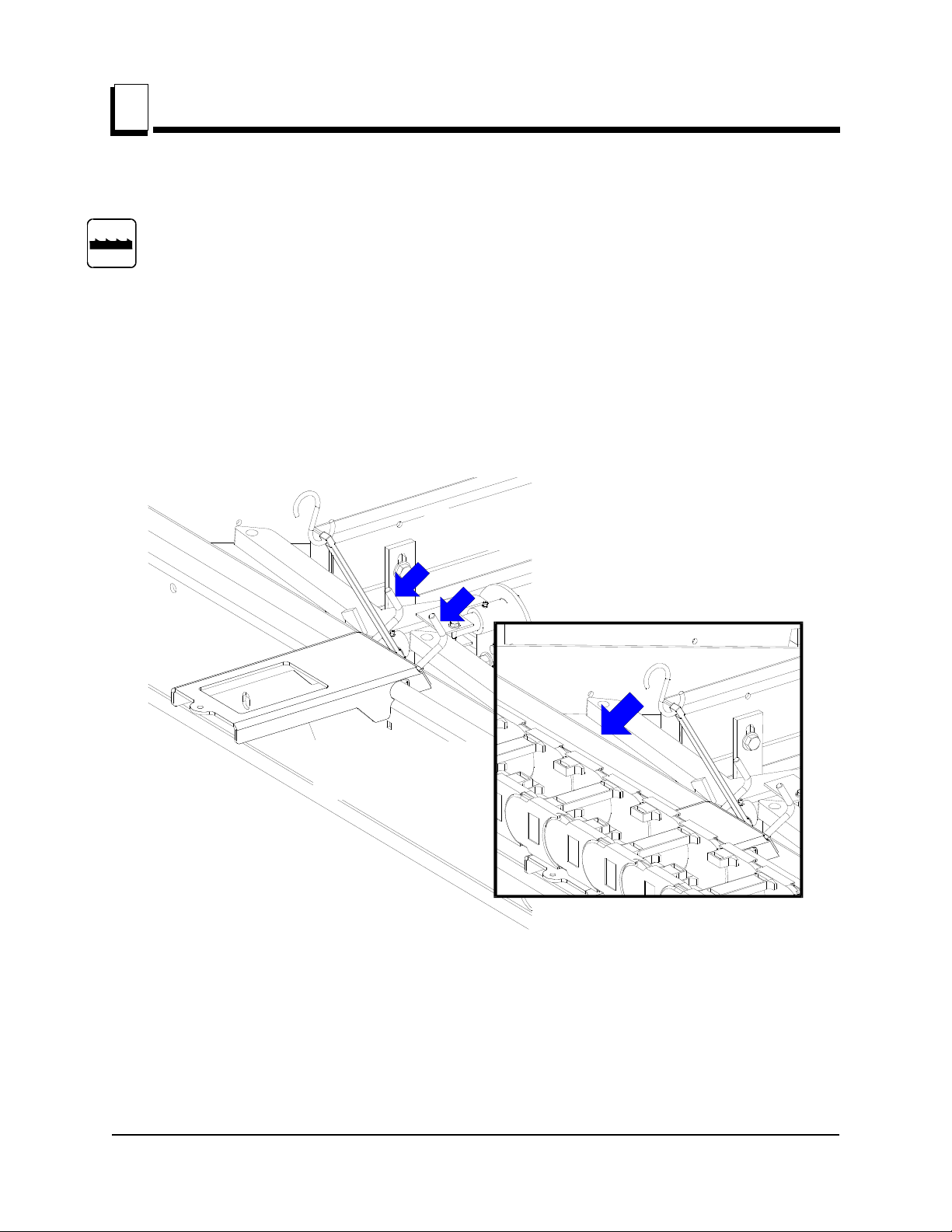
1. Remove the chain support bracket (See Section 1.1).
2. Pull the chain up at a few locations to determine if it moves freely. If you detect the chain
is frozen, proceed to the recommended deicing procedure below.
3. If the chain seems to move freely by hand, use the power feed to slowly move the saw
carriage toward the rear of the mill. Since the saw carriage returns only at full speed,
moving the saw carriage forward will allow you to slowly engage the cable chain to be
sure it is not frozen. If you detect the chain is frozen, proceed to the recommended
deicing procedure below.
Recommended Cable Chain deicing Procedure
To de-ice the chain, apply a salt solution (preferably calcium chloride and water) to the
entire length of the chain. Allow the solution to sit until the chain can move freely. The
strength of the solution and time required to free the chain will depend on how cold the
weather is and how much ice has accumulated in the chain.
Before storing the sawmill after using the salt solution, be sure to rinse the salt from any
metal portions of the sawmill frame to prevent corrosion. Refer to the recommended
cold-weather storage procedure below to prevent the chain from freezing.
Recommended Cable Chain Ice Prevention Procedure
Before storing the sawmill in freezing temperatures, apply a 50/50 solution of
environmentally safe antifreeze (Sierra) and water to the cable chain. A garden sprayer
can be used to apply the solution.

Remote Operation
Hydraulic Control Operation
1
1-8 ROdoc121516 Remote Operation
1.5 Hydraulic Control Operation
The hydraulic control levers become operational when the contacts at the bottom of the
carriage touch the power strip on the frame tube. The hydraulic control levers will only
work when the cutting head is close enough to the front end of the mill to touch the power
strip.
See Figure 1-6. Hydraulic units have eleven control levers to load, clamp, turn and level
logs.
Use the hydraulic control levers to get the mill ready to load a log.
DANGER! Keep all persons out of the path of moving
equipment and logs when operating sawmill or loading and
turning logs. Failure to do so will result in serious injury.
CAUTION! Always make sure the engine is running before
operating the hydraulic controls. Operating the controls
without the engine running will result in power drainage
from the battery.
FIG. 1-6
Clamp
In/Out
Clamp
Up/Down
Turner
Front Toe
Board
Rear Toe
Board
Loader

Remote Operation
Hydraulic Control Operation
Remote Operation ROdoc121516 1-9
1
1. Move the clamp out and down so it will not get in the way of logs being loaded onto the
bed.
Lower the clamp in/out lever to move the clamp out toward the loading side of the
sawmill.
Lower the clamp up/down lever to lower the clamp below bed level.
2. Raise the log loader lever to extend the legs of the log loader out as far as they will go.
3. The chain securing the log loading arm to the bed frame will be tight. Manually push the
log loader arm until there is slack in the chain.
4. Unchain the loading arm from the bed frame.
5. Lower the turner lever to completely lower the turner arm. Notice that after the turner arm
is all the way down, the side support braces will begin to lower. Release the turner lever
after the turner arm is lowered, but before the side supports begin to lower. This stops the
log being loaded from damaging the turner and/or falling off the side of the sawmill.
6. When raising the turner lever, the side supports rise first. After reaching a fully vertical
position, the turner arm will engage and start to rise.
7. Manually lower the log loader so it rests on the ground.
CAUTION! Be careful when manually lowering the log
loader. Do not drop the loader onto the ground or perform
any action which might break the velocity fuse valves on
the loader cylinders. These valves control hydraulic flow
and are necessary to prevent the loading arm from
collapsing during use.
8. Lower the loader lever to lower the loading arm as far as it will go. Logs must be rolled
onto the loading arms one at a time.
9. The front, middle and rear toe boards should be below bed level. Once a tapered log has
been loaded, the front or rear end of the log may be lifted to parallel the heart of the log to
the path of the blade.
The front toe board is raised by lifting the front toe board lever up.The middle toe board is
raised by lifting the middle toe board lever up. The rear toe board is raised by lifting the
rear toe board lever up. Once a flat has been made and the log is ready to be turned,
push the appropriate toe board lever down to lower either toe board until it falls below the
level of the bed.

Maintenance & Troubleshooting
Control Pivot Lubrication
2
2-1 ROdoc121516 Maintenance & Troubleshooting
SECTION 2 MAINTENANCE & TROUBLESHOOTING
2.1 Control Pivot Lubrication
Lubricate the control pivot as necessary to allow the control box to pivot freely. Apply a
NLGI No. 2 grade lithium grease to the grease fitting supplied above the pivot locking
handle.
See Figure 2-1.
FIG. 2-1
AR
Control pivot
grease fitting
3H0473B

Maintenance & Troubleshooting
Clean The Cable Chain & Support Tray
Maintenance & Troubleshooting ROdoc121516 2-2
2
2.2 Clean The Cable Chain & Support Tray
As you operate the sawmill, be aware of any pieces of debris that may fall on the cable
chain and/or support tray. Stop the sawmill and immediately remove any pieces of wood,
bark or anything else that may divert the path of the chain or cause it to jam.
Clean the cable chain and support track of sawdust buildup every eight hours of
operation. Blow or brush the sawdust from the track and tray and remove any
accumulated sawdust that is high enough to contact the chain/tray.
2.3 Cable Chain Repair
If a component of the cable chain breaks or is missing, replace the component.
CAUTION! Do not operate the remote sawmill if the cable
chain is damaged or components of the chain are missing.
The chain components are interlocking and continued
operation will cause more damage to the chain.
See Figure 2-2. To disassemble the chain use a screwdriver to pry the connecting links
apart. After removing the connecting links, the side plates can be disassembled by pulling
them apart at an angle.
FIG. 2-2
3H0485

Maintenance & Troubleshooting
Cable Chain And Support Tray Alignment
2
2-3 ROdoc121516 Maintenance & Troubleshooting
2.4 Cable Chain And Support Tray Alignment
During each sawmill setup, check the alignment of the cable chain and the support tray:
1. The chain should travel in a straight line. Traveling at an angle will cause the chain to
prematurely wear and break. Check the alignment of the chain by measuring from the
sawmill frame tube to the center of the chain at the top and bottom. The measurements
should be the same (±1/8”).
See Figure 2-3.
Loosen the mounting bolts at the top or bottom of the chain to adjust the distance from the
sawmill frame tube.
FIG. 2-3
A
B
A = B (±1/8")
3H0507B
Front End View of
Remote Chain

Maintenance & Troubleshooting
Cable Chain And Support Tray Alignment
Maintenance & Troubleshooting ROdoc121516 2-4
2
2. The chain support tray must be level to prevent premature wear of the chain. Use a
square to check the angle of the tray to the sawmill frame. Check at several locations
along the length of the tray.
See Figure 2-4.
Bend the tray up or down as necessary to square it to the sawmill frame.
FIG. 2-4
3H0508B
Front End View of
Remote Chain
90°

REPLACEMENT PARTS
3
3-1 HDSdoc121516 REPLACEMENT PARTS
SECTION 3 REPLACEMENT PARTS

REPLACEMENT PARTS
How To Use The Parts List
REPLACEMENT PARTS HDSdoc121516 3-2
3
3.1 How To Use The Parts List
Use the table of contents or index to locate the assembly that contains the part you need.
Go to the appropriate section and locate the part in the illustration.
Use the number pointing to the part to locate the correct part number and description in the
table.
Parts shown indented under another part are included with that part.
Parts marked with a diamond () are only available in the assembly listed above the part.
See the sample table below. Sample Part #A01111 includes part F02222-2 and subassembly
A03333. Subassembly A03333 includes part S04444-4 and subassembly K05555. The diamond ()
indicates that S04444-4 is not available except in subassembly A03333. Subassembly K05555
includes parts M06666 and F07777-77. The diamond () indicates M06666 is not available except in
subassembly K05555.
To O r d e r P a r ts :
From Europe call our European Headquarters and Manufacturing Facility in Kolo, Poland at
+48-63-2626000 or +48-3912-1319. From the continental U.S., call 1-800-448-7881 to order
parts. Have your customer number, vehicle identification number, and part numbers ready
when you call.
From other international locations, contact the Wood-Mizer distributor in your area for parts.
3.2 Sample Assembly
REF DESCRIPTION (Indicates Parts Available In Assemblies Only) PART # QTY.
SAMPLE ASSEMBLY, COMPLETE (INCLUDES ALL INDENTED PARTS BELOW) A01111 1
1Sample Part F02222-22 1
Sample Subassembly (Includes All Indented Parts Below) A03333 1
2Sample Part (Indicates Part Is Only Available With A03333) S04444-4 1
Sample Subassembly (Includes All Indented Parts Below) K05555 1
3Sample Part (Indicates Part Is Only Available With K05555) M06666 2
4Sample Part F07777-77 1

REPLACEMENT PARTS
Motor Assembly
3
3-3 HDSdoc121516 REPLACEMENT PARTS
3.3 Motor Assembly
REF. DESCRIPTION (Indicates Parts Available In Assemblies Only) PART # QTY
1MOTOR, 18.5 kW/380V 1LA7166-2AA60-Z ELECTRIC 087397 1
2BUSHING, SPLIT TAPER (E25 MOTOR KIT) 085714 1
3PLATE, E25LT80 MOTOR MOUNTING 090089-1 1
4COVER WELDMENT, E25LT80 BELT - REAR 090050-1 1
5KEY, 9.5h7x9.5x3.8 087384 1
6PULLEY, 15/18.5kW ELECTRIC MOTOR 085671 1
7GUARD WELDMENT, E25LT80 MOTOR BELT 090046-1 1
8BELT, 3BX74 DRIVE 014249 1

REPLACEMENT PARTS
Control Box
REPLACEMENT PARTS HDSdoc121516 3-4
3
3.4 Control Box
REF. DESCRIPTION (Indicates Parts Available In Assemblies Only) PART # QTY
PULPIT OPERATORA MASZYNY BOX, LT40/70 AC CONTROL 500630 1
1BOX WELDMENT, AC CONTROL 086546-1 1
2SWITCH, 1992GS PWR/FEED (SERVICE PACKAGE) E20438 1
3SWITCH, 1992 UP/DOWN (SERVICE PACKAGE) E20440 1
4RAIL, CIRCUIT BREAKER 015310 1
5BREAKER, 15A MANUAL RESET E20430 3
6BOLT, 8-32X1/2 SL RND HEAD MACHINE F05004-12 4
7NUT, #8-32 KEPS F05010-41 4
8WASHER, EMERGENCY STOP SWITCH 086561 1
9SWITCH, XB4 BS542 EMERGENCY STOP 086556 1
PLATE, COMPLETE FRONT CONTROL BOX 086562 1
10 PANEL WLDMT, FACE 015302 1
11 DECAL, GAS FACE PANEL 015271 1
12 METER, HOUR RECTANGLE MOUNT 015401 1
13 SCREW, 6-32X3/4 SBHC SS F05004-93 2
14 NUT, #6-32 KEPS F05010-59 2
15 SWITCH, KEY P04350 1
16 WASHER, 1/2X3/4X1/16 NYLON P05251-1 2
17 SWITCH, DPDT TOGGLE 21A REV MOM SPADE 024200 2
18 BOOT, TOGGLE SWITCH P02575 2
19 POTENTIOMETER ASSY, FEED RATE CONTROL 024450 1
20 KNOB, SPEED CONTROL P06257 1
21 STANDOFF, PCB 1/2 #6 FEMALE THREADING 023147 4
22 PCB ASSY, LED GAS/ELECTRIC SAWMILL 1997 015416 1
23 BOLT, #10-24 X 1/2 PHILLIPS PAN HEAD, TYPE 23 F05015-17 8
24 GASKET, FRONT PANEL 015270 1
25 COVER WELDMENT 015304 1
26 BOLT, #10-24 X 1/2 PHILLIPS PAN HEAD, TYPE 23 F05015-17 4
27 SEAL, 1 1/4 RING LQTI W/RETAINER 015430 1

REPLACEMENT PARTS
Control Box
3
3-5 HDSdoc121516 REPLACEMENT PARTS
28 CONNECTOR, 1 1/4 STRAIGHT METAL CONDUIT 024402 1
29 CONDUIT, 1-1/4IN FLEX 024401 1
30 PLUG, ASO75 OILTITE E20570 1
31 SCREW, 10-24X3/8 PH PHIL MS W/NEO WASHER F05004-148 4
32 NUT, #10-24 KEPS F05010-14 4
33 GREASE, DRUM SWITCH A20463 1
34 NUT, M5-8-FE/ZN5 DIN985 F81030-2 3
35 FITTING, ELZ-4 F81086-1 1
36 SCREW, M3 X 20-5.8-A SLOTTED CHEESE HEAD ZINC F81000-8 1
37 WASHER, 4.3 FLAT ZINC F81051-2 1
38 WASHER, 3.2 A MS FLAT SPECIAL F81050-1 1
39 NUT, M3-6-HEX NYLON ZINC LOCK F81028-2 1
40 GROMMET, RUBBER 087065 1
41 CONNECTOR, MAXI-FLEX GP29 086576 1
REF. DESCRIPTION (Indicates Parts Available In Assemblies Only) PART # QTY
Other manuals for LT70 Series
6
Table of contents
Other woodmizer Construction Equipment manuals
Popular Construction Equipment manuals by other brands

Newstripe
Newstripe NewRider 5000 manual

Central Machinery
Central Machinery 38470 Owner's manual & safety instructions

Watts
Watts Pronto! FD-190-PR-60 Instructions for installing

NorthStar
NorthStar 4065 Installation, operation and maintenance manual

Dynapac
Dynapac DTR75 Operating instruction

Dynapac
Dynapac CC424HF instruction manual

Husqvarna
Husqvarna WS 482 HF Operator's manual

Global Manufacturing
Global Manufacturing Viber Mini Backpack operating instructions

Clarke
Clarke Strong Arm CCB1B Operation instructions

Fassi
Fassi F 240.24 Use and maintenance

Zoomlion
Zoomlion ZCC1300 Maintenance manual

Husqvarna
Husqvarna 1-10DS Operator's manual