woodmizer KD150 Series User manual

User Manual
KD150 Series
Wood-Mizer LLC
8180 West 10th Street
Indianapolis, IN 46214
Wood-Mizer
Wood-Mizer
World Headquarters


Safety Guidelines .......................................................................................................................................................... 1
Precautions ............................................................................................................................................................................................ 1
Electrical Grounding .......................................................................................................................................................................... 1
Your Kiln ......................................................................................................................................................................... 2
How your Dehumidication Kiln Works .................................................................................................................................. 2
Getting Started ............................................................................................................................................................. 2
Floors ...................................................................................................................................................................................................... 2
Ceilings ................................................................................................................................................................................................... 2
Doors ....................................................................................................................................................................................................... 2
Construction Guidelines ................................................................................................................................................................. 3
Baes and Deectors ....................................................................................................................................................................... 3
Power Vent ............................................................................................................................................................................................ 3
Chamber Plans ............................................................................................................................................................... 4
Chamber Dimensions ........................................................................................................................................................................ 7
Wall Details ............................................................................................................................................................................................ 8
Front Elevation .................................................................................................................................................................................... 9
Door Framing ..................................................................................................................................................................................... 10
Door Gasket Installation ................................................................................................................................................................ 13
Unit Installation Drawing ............................................................................................................................................................. 14
Deectors and Baes .................................................................................................................................................................... 15
Power Vent Wiring ........................................................................................................................................................................... 16
Equipment Installation ............................................................................................................................................... 16
Wet and Dry Bulb Sensors ......................................................................................................................................... 17
Sensor Technology ........................................................................................................................................................................ 17
Dry Bulb Sensor .............................................................................................................................................................................. 17
Wet Bulb Sensor ............................................................................................................................................................................. 17
Wet Bulb & Dry Bulb Installation .............................................................................................................................................. 17
Kiln Control ................................................................................................................................................................. 18
How the Controller Works ............................................................................................................................................................ 18
Using the KD150 ............................................................................................................................................................................... 18
Parameters .......................................................................................................................................................................................... 18
Settable Parameters ........................................................................................................................................................................ 18
Serial Interface ................................................................................................................................................................................. 18
Alarm Conditions / Messages ...................................................................................................................................................... 19
Technical Specications ................................................................................................................................................................ 19
Control Wiring ................................................................................................................................................................................... 19
Wiring Diagram ........................................................................................................................................................... 20
Drying Lumber ............................................................................................................................................................. 21
Placing Stickers and Loading Lumber...................................................................................................................... 21
Ensuring Proper Airow .............................................................................................................................................. 21
Drying Schedules ........................................................................................................................................................ 21
Wood Groups ............................................................................................................................................................. 22
Lumber Types ............................................................................................................................................................. 22
Moisture Removal Rates ............................................................................................................................................ 22
Drying Schedules ....................................................................................................................................................... 22
Drying Rates (North American Measure) ............................................................................................................... 23
Drying Rates (Metric) ................................................................................................................................................ 24
Table of Contents

Kiln Sample Boards .................................................................................................................................................... 25
Uses for Sample Boards ............................................................................................................................................. 25
Taking Samples ............................................................................................................................................................ 25
Record Keeping........................................................................................................................................................... 26
Drying Rate Index (DRI) ............................................................................................................................................. 27
Drying Tips ................................................................................................................................................................... 28
Drying Charts ............................................................................................................................................................. 29
Maintenance .............................................................................................................................................................. 31
General Maintenance .................................................................................................................................................................... 31
Air Inlet Filters .................................................................................................................................................................................. 31
Refrigerant Charging Procedure ............................................................................................................................................... 31
Controller Factory Setting .......................................................................................................................................................... 31
Appendix ...................................................................................................................................................................... 32
Terminology ....................................................................................................................................................................................... 32
Troubleshooting .......................................................................................................................................................... 33
Upgrades & Accessories ............................................................................................................................................ 34
Spray Systems Kit ............................................................................................................................................................................ 34
Heat Booster Package .................................................................................................................................................................. 34
Kiln Store ..................................................................................................................................................................... 35
Warranty ..................................................................................................................................................................... 35
Service Log ................................................................................................................................................................. 37
Wet Bulb & Dry Bulb Installation Template .................................................................................................... 36
Notes ............................................................................................................................................................................ 39
Data Sticker ................................................................................................................................................................. 39

Getting Service
Wood-Mizer is committed to providing you with the latest technology, best quality and
strongest customer service available on the market today. We continually evaluate our
customers’ needs to ensure we’re meeting current wood-processing demands. Your
comments and suggestions are welcome.
General Contact Information
Toll free phone numbers are listed below for the continental U.S. and Canada. See the next
page for contact information for more Wood-Mizer locations.
Office Hours: All times are Eastern Standard Time.
Please have your vehicle identification number and your customer number ready when you call.
Wood-Mizer will accept these methods of payment:
Visa, Mastercard, or Discover
COD
Prepayment
Net 15 (with approved credit)
Be aware that shipping and handling charges may apply. Handling charges are based on size
and quantity of order. In most cases, items will ship on the day they are ordered. Second Day
and Next Day shipping are available at additional cost.
If your equipment was purchased outside the United States or Canada, contact the dis-tributor
for service.
United States Canada
Sales 1-800-553-0182
Service 1-800-525-8100
Website www.woodmizer.com
1-877-866-0667
1-877-866-0667
www.woodmizer.ca
Monday - Friday Saturday
(Indianapolis Office Only)
Sunday
8 a.m. to 5 p.m. 8 a.m. to 12 p.m. Closed
KD150 12/22/17

1
Refrigerant!
• Unit contains Rs-24 refrigerant under high pressure.
Refrigerant must be recovered to relieve pressure
before servicing.
• DO NOT use unapproved refrigerants, substitutes
or additives.
• Failure to abide by these guidelines can result in
death, injury and property damages.
• Contact Nyle’s service department for more
information on refrigerant options.
Read through entire manual before installing, operating, or servicing this unit.
Failure to follow any steps or guidelines could result in personal injury, death, destruction
of property or may cause the unit to become inoperable. These are the “original Instructions for this unit.”This
manual must be kept with the unit at all times.
Safety Guidelines
Precautions
Do not operate if the unit or any of its parts:
• Have been exposed to re.
•Have been submerged in or exposed to excessive
water.
• Has signicant interior or exterior damage.
If any of the above are suspected make sure to have
your unit serviced by a qualied professional before
continuing operation.
*The unit is rated for an ambient temp of 10-40° C, 80 RH % at a
maximum 200 meters.
Electrical Grounding
The unit must be grounded.
Failure to ground the unit will result in unreliable
performance or an inoperative unit.You can ground
the unit by connecting the unit to a grounded
metal, permanent wiring system. Make sure the
unit is in accordance with national and local electrical
codes. If you don’t know the building codes in your
area or need more information, please contact your
municipal oce.
*Normally airborne noise is rated at 77 dB.
Electrical Shock!
•Turn off power to unit
before service.
• Make sure wires are labeled
before disconnecting.
• Test unit after reconnecting
wires.
• Failure to do the above could result in death or injury.
High Temperatures!
• Kiln chamber can reach
internal temperatures of
over 90°F. working in these
temperatures can cause heat stroke and minor burns.
• Pregnant women, children, the elderly and those
with signicant health issues are at higher risk of heat
stroke and must be supervised in high temperatures.
• Kiln operators should check for temperature and
take proper safety precautions before entering the
kiln chamber.
• DO NOT purge or
pressurize this system with
oxygen to test for leakage.
Using oxygen may cause
explosive reaction.
Explosion Hazard!
Supervision!
- The appliance is not to be used by person (including
children) with reduced physical, sensory or mental
capabilities, or lack of experience and knowledge,
unless they have been given supervision or instruction.
- Supervised children are not to play with the appliance.

2
Your Kiln
How your Dehumidification Kiln Works
Thank you for purchasing a Wood-Mizer
Dehumidification Kiln and taking the first step
towards making the lumber industry cleaner and
more efficient! Years of development, innovation
and the highest quality materials have gone into
building your kiln. It’s our dedication to efficiency
that sets Wood-Mizer kilns apart from the rest
making your system the best on the market.
During kiln drying, moisture from green lumber is
evaporated into the air increasing the humidity inside
the chamber. The lumber can’t continue to dry if the
air becomes over-saturated therefore the moisture
must be periodically removed from the chamber.
In a conventional kiln moisture would be expelled
through venting. Venting causes a signicant loss
of heat resulting in a waste of energy to bring the
kiln back up to temperature.
Instead of venting,Dehumidification Kilns
utilize a refrigeration system that condenses
the excess moisture. This moisture is then
drained off retaining the existing heat energy. After
the moisture is removed and heat is reintroduced to
the dry air it is pumped back into the kiln
chamber to start the process over. Unlike
conventional kilns the heater in your kiln is only
used during the initial warm up and sometimes
when temperature increases are desired during the
cycle, saving you time and money. But that’s not all
your new kiln has to offer!
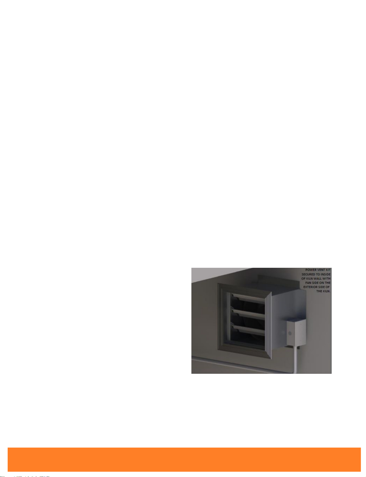
Though Wood-Mizer kilns don’t rely on venting
to get rid of moisture, a Vent System is supplied
to add extra control of your kiln temperature. If
the internal kiln temperature exceeds what’s
required, these vents can be opened to remove
excess heat and bring the temperature back to
where it needs to be.
Finally Wood-Mizer offers a wide variety of upgrades
and accessories to enhance your kiln drying experience.
See the upgrades and accessories section on page
34 for more information. By purchasing a Kiln you
have the support of the service team, the very
same professionals that built and tested your
unit. Enjoy your new system!
Getting Started
Please read through carefully as some options may not
apply.
Floors
Concrete floors with insulation installed underneath
is recommended for best results. However if
the kiln is going to be on an existing concrete
floor, the insulation may be omitted. Concrete must
not extend beyond the kiln walls.
Wood floors may be used but must be built
to construction guidelines (see Pg 3)
Ceilings
If the kiln chamber is a freestanding outside building,
the attic space must be well ventilated through
the eaves. This is done to avoid any moisture
buildup in this space, which will condense on the
cold roof and drip onto the insulation.
An interior kiln can have the ceiling insulation
open to the atmosphere.
Ceilings must be built to construction
guidelines. (Pg 3)
Doors
At the front of the kiln chamber install bay/
loading doors with at least two sides hinges and
a center door latch to close (recommended). Top
hinged or a lift off doors are also acceptable.
At least one access door should be installed in
the back of the chamber to allow for service of
the dehumidifier and/or lumber monitoring.
All installed doors must:
•Be built to construction guidelines. However
they may be lightened by increasing the stud
spacing and using 3/8” plywood. The lighter
weight will reduce the load on the hinges
• Have a vapor barrier.
•Have gaskets wherever the door meets the kiln;
this will give a good, airtight t.
•Have a scraper type weather strip to reduce air
leakage if door sill is not present.

3
•Close tightly against the gasket using turnbuckles,
tarp straps, lag studs with wing nut, etc.
Remember: There will be considerable expansion
and contraction during kiln use so it is imperative
to plan your kiln door construction accordingly.
While outside electronic moisture meters can be
used to avoid entering the kiln, during the drying
cycle, Wood-Mizer strongly recommends
regular checks inside the kiln to visually
inspect the surface or ends for checks, mold,
stain as well as testing with a hand held meter.
Construction Guidelines
Please reference Chamber Plans for more information
on construction.
Step 1: Build all walls, ceilings and floors with a 2”
x 4”framework using blue or pink Styrofoam
(extruded polystyrene) friction fitted between the
studs.
Step 2: Cover the interior face of the studs with a
1” layer of Celotex Thermax ( for better results
overlap two ½” layers).
Celotex Thermax is foil faced
polyisocyanurate (urethane) board which is
orange or yellow in color and is available in 4’x 8’
sheets of various thicknesses. Celotex Thermax is a
trade name, similar products under other trade
names are acceptable.
Note: If you want to use spray foam insulation,
only use urethane based spray foam applied at
2.2lb/cu ft. Fiberglass is never recommended.
Step 3: Caulk joints and nail heads with a high
temperature silicone (optional: apply aluminum
tape over silicone)
Step 4: Cover Thermax with one or two layers of
6 mil polyethylene, then enclose with ½”CDX or
marine grade plywood.
Step 5: Coat CDX interior surface with “mobile
home or metal roofing aluminum paint”
Note: Paint is an asphalt based coating with
powdered aluminum and fiber for strength,
available in most hardware stores. Re-coat as
necessary every year.
Step 6: Finish exterior walls to suit your tastes, but
avoid galvanized steel or other ferrous sidings.
Once you have completed construction of the kiln
chamber install the following air deectors and
baes to control the airow within the chamber.
Baes and Deectors
Do not underestimate the eect of baing. Correct
baing will result in faster and more even drying.
The benets more than oset the extra time and
eort to correctly place the baes.
•Corner deector: typically made of plywood
are used to help turn the airow.
•Top Bae: Hinged bae that falls from the fan
wall to the top of the load used to compensate
for dierent load sizes, and allow for shrinkage
of the board pile.
•Side Bae: Bae that closes in the open space
when lumber that does not ll the entire width.
This bae can be xed or portable.
Please reference pg 13 for more information on
deectors and baes.
Power Vent
The Power Vent is to be secured to the inside of
the kiln wall with the fan side facing the exterior.

4
Do It Yourself Chamber Plans
12"
MIN.
18" MINIMUM
MAX. BY CUSTOMER
FOR ADEQUATE
WORKING ROOM
RIDGE VENT
2" x 6"
SCREENED VENTSCREENED VENT
DOUBLE 2"x4"
TOP PLATE
EXHAUST VENT
(10"x10" R.O.)
INTAKE VENT
(10"x10" R.O.)
PROVIDE AIR SPACE
BETWEEN INSULATION
AND ROOF
1/2" CDX PLYWOOD
BE SURE OUTSIDE WALL
IS WELL VENTILATED
ANCHOR BOLTS
4'-0" O.C. TYP
LUMBER
PACKAGE
4" CONCRETE PAD
REINFORCED AS
NECESSARY
2 LAYERS OF
2" "CELOTEX" FOIL FACED
POLYISOCYANURATE OR EQUIVALENT
(3 LAYERS OPTIONAL) AT LEAST R30
CDX PLYWOOD
OVER 6 MIL POLY
CDX PLYWOOD
OVER 6 MIL POLY
VAPOR BARRIER
2" BLUE STYROFOAM
W/ 1 LAYER 6 MIL POLY
BETWEEN CONCRETE PAD
AND INSULATION
2" "CELOTEX"
COAT WALLS
AND CEILING
W/ FIBERED
ALUMINUM
ROOF COATING
LAYER OF PLYWOOD TO
PROTECT TOP OF LUMBER
AND SEPARATE AIRFLOW
2" BLUE STYROFOAM
AROUND PERIMETER
AIR
INTAKE
2" "CELOTEX" FOIL
FACED PLOYISOCIANURATE
INSULATED BOARD
AIR FLOW
CDX PLYWOOD
SHEATHING W/
ASPHALT SHINGLES
FLASHING
TREATED SILL
WEATHERPROOF
ENCLOSURE TO
HOUSE CONTROLLER
2"x4" LEDGE TO
CARRY EDGE OF
PLYWOOD ALONG
WALL
2" x 6"
2" x 6"
DEHUMID-
IFIER
*FIBERGLASS INSULATION MAY BE USED
BUT WALL INSULATION MUST HAVE AT LEAST
1-1/2" CLOSED CELL INSULATION AS INSIDE
SHEATHING. THE MINIMUM R-FACTOR SHOULD
BE AT LEAST R-30.
AIR FLOW
SHEET
SCALE
TITLE
CHECKED
DRAWN
PROPRIETARY AND CONFIDENTIAL
THE INFORMATION CONTAINED IN
THISDRAWING IS THE SOLE PROPERTY OF
NYLE SYSTEMS. ANY REPRODUCTION IN
PART OR AS A WHOLEWITHOUT THE
WRITTEN PERMISSION OF NYLE SYSTEMS IS
PROHIBITED.
5
4
3
2
1
DWG FILE NAME
CUSTOMER
REV
1
KD150 KILN
CHAMBER
SECTION B
REFERENCE
2/11/2013

5
0,1
'
(
,17$.(9(17%<1</(
$//2:[5272,167$//
(;+$8679(17%<1</(
$//2:[5272,167$//
&21752/%2;
9
$03
287/(7)25
'(+80,',),(5
'5$,13,3(
25+26(
/80%(53$&.$*(
237,21$/
'225
/2&$7,21
[/('*(
&87287)2581,7
3/<:22'%$))/(&29(56723
2)3$&.$*($1'$//23(163$&(
$5281'7+('(+80,',),(5
3/<:22'29(5
3$&.$*(
6+$'('
6+((7
6&$/(
7,7/(
&+(&.('
'5$:1
35235,(7$5<$1'&21),'(17,$/
7+(,1)250$7,21&217$,1(',1
7+,6'5$:,1*,67+(62/(3523(57<2)
1</(6<67(06$1<5(352'8&7,21,1
3$5725$6$:+2/(:,7+2877+(
:5,77(13(50,66,212)1</(6<67(06,6
352+,%,7('
':*),/(1$0(
&86720(5
5(9
KD150.,/1&+$0%(5
3/$19,(:
176

6
)
&
:22'(16833257
)25'(+80,',),(5
,17$.(9(17
%2;/2&$7,21
(;+$8679(17
%2;/2&$7,21
,167$//%$))/(%(7:((1
(1'2)3,/($1':$//
7235(9(17$,5)/2:
$,5287
'(+80,',),(5
%$))/(
%$))/(
6+((7
6&$/(
7,7/(
&+(&.('
'5$:1
35235,(7$5<$1'&21),'(17,$/
7+(,1)250$7,21&217$,1(',1
7+,6'5$:,1*,67+(62/(3523(57<2)
1</(6<67(06$1<5(352'8&7,21,1
3$5725$6$:+2/(:,7+2877+(
:5,77(13(50,66,212)1</(6<67(06,6
352+,%,7('
':*),/(1$0(
&86720(5
5(9
KD150.,/1&+$0%(5
6(&7,219,(:
5()(5(1&(

7
FT. C E F
300 8 3 26 13 7
500 8 3 42 21 7 12 3 28 14 13 7
750 8 4 46 23 8 12 3 42 21 13 7
1000 8 4 62 31 8 7 12 3
54
27 13 8 7
3/4"
KD150
KD150
Chamber Dimensions

8
Wall Details

9
Front Elevation

10
Door Framing

11

12

13
Door Gasket Installation - Gasket and Door Kits Available

14
6+((7
6&$/(
7,7/(
&+(&.('
'5$:1
35235,(7$5<$1'&21),'(17,$/
7+(,1)250$7,21&217$,1(',1
7+,6'5$:,1*,67+(62/(3523(57<2)
1</(6<67(06$1<5(352'8&7,21,1
3$5725$6$:+2/(:,7+2877+(
:5,77(13(50,66,212)1</(6<67(06,6
352+,%,7('
':*),/(1$0(
&86720(5
5(9
KD150
UNIT
INSTALLATION DRAWING
176
Unit Installation Drawing

15
$,5)/2:
$,5)/2:
1</(//2:7(03(5$785('(+80,',),&$7,21.,/1
6+((7
6&$/(
7,7/(
&+(&.('
'5$:1
35235,(7$5<$1'&21),'(17,$/
7+(,1)250$7,21&217$,1(',1
7+,6'5$:,1*,67+(62/(3523(57<2)
1</(6<67(06$1<5(352'8&7,21,1
3$5725$6$:+2/(:,7+2877+(
:5,77(13(50,66,212)1</(6<67(06,6
352+,%,7('
':*),/(1$0(
&86720(5
5(9
KD150&+$0%(5
5()(5(1&(
Deectors and Baes
Other manuals for KD150 Series
1
Table of contents
Other woodmizer Dehumidifier manuals