woodmizer TRB-S Guide

Surge Brake Trailer
Safety, Operation, Maintenance
& Parts Manual
TRB-S Trailer Option
Safety is our #1 concern! Read and understand
all safety information and instructions before oper-
ating, setting up or maintaining this machine.
September 2008
Form #794

ii SB97doc042718 Table of Contents
Table of Contents Section-Page
SECTION 1 SURGE BRAKE HITCH 1-1
1.1 Operation ................................................................................................1-1
1.2 Maintenance ...........................................................................................2-1
SECTION 2 PARTS LISTS 3-1
2.1 Trailer Hitch Assembly, Surge Brake ....................................................3-1
2.2 Trailer Axle Assembly, Surge Brake......................................................3-3
LT30 Super Rev. H4.00+
LT40 Super Rev. H5.00+
LT30HD Rev. H8.00+
LT40HD Rev. H8.00+
LT30HD Super Rev. H8.00+
LT40HD Super Rev. H8.00+
LT50HD Rev. A1.00+
2.3 Trailer Axle Assembly, Surge Brake......................................................3-5
LT30 Super Rev. F7.00 - H3.00
LT40 Super Rev. F8.00 - H4.00
LT30HD Rev. G1.00 - H7.00
LT40HD Rev. G1.00 - H7.00
2.4 Outriggers...............................................................................................3-7
2.5 Outrigger Assembly, Long .....................................................................3-8
LT30 Super Rev. H2.00+
LT40 Super Rev. H3.00+
LT30HD Rev. H6.00+
LT40HD Rev. H6.00+
2.6 Outrigger Assembly, Long ...................................................................3-10
LT30 Super Rev. G6.00 - H1.00
LT40 Super Rev. G7.00 - H2.00
LT30HD Rev. G9.00 - H5.00
LT40HD Rev. G9.00 - H5.00
2.7 Outrigger Assembly, Long ...................................................................3-12
LT30 Super Rev. F7.00 - G5.00
LT40 Super Rev. F8.00 - G6.00
LT30HD Rev. G1.00 - G8.00
LT40HD Rev. G1.00 - G8.00
2.8 Outrigger Assembly, Front...................................................................3-14
LT40 Super Rev. G7.00+
LT40HD Rev. G9.00+
2.9 Outrigger Assembly, Front...................................................................3-16
LT40 Super Rev. F8.00 - G6.00
LT40HD Rev. G1.00 - G8.00
2.10 Outrigger Assembly, Long (LT30 Super) ............................................3-18
LT30 Rev. J9.00+
LT30 Super Rev. H2.00+
TOC

Table of Contents Section-Page
Table of Contents SB97doc042718 iii
2.11 Outrigger Assembly, Short Front .........................................................3-20
LT30 Super Rev. G6.00+
LT40 Super Rev. G7.00+
LT30HD Rev. G9.00+
LT40HD Rev. G9.00+
2.12 Outrigger Assembly, Short Front .........................................................3-22
LT30 Super Rev. F7.00 - G5.00
LT40 Super Rev. F8.00 - G6.00
LT30HD Rev. G1.00 - G8.00
LT40HD Rev. G1.00 - G8.00
2.13 Outrigger Assembly, Rear....................................................................3-24
LT40 Super Rev. G7.00+
LT40HD Rev. G9.00+
2.14 Outrigger Assembly, Rear....................................................................3-26
LT40 Super Rev. F8.00 - G6.00
LT40HD Rev. G1.00 - G8.00
2.15 Outrigger Assembly, Short Rear ..........................................................3-28
LT30 Super Rev. G6.00+
LT40 Super Rev. G7.00+
LT30HD Rev. G9.00+
LT40HD Rev. G9.00+
2.16 Outrigger Assembly, Short Rear ..........................................................3-30
LT30 Super Rev. F7.00 - G5.00
LT40 Super Rev. F8.00 - G6.00
LT30HD Rev. G1.00 - G8.00
LT40HD Rev. G1.00 - G8.00
2.17 Log Loading Ramps (LT30/LT40).......................................................3-32
2.18 Trailer Lights........................................................................................3-33
LT40 Super Rev. J6.00+
LT30HD Rev. K2.00+
LT40HD Rev. K4.00+
2.19 Trailer Lights........................................................................................3-35
LT30 Super Rev. F7.00+
LT40 Super Rev. F8.00 - J5.03
LT30HD Rev. G1.00 - K1.03
LT40HD Rev. G1.00 - K3.01
INDEX 1-I

Surge Brake Hitch
Operation
1
1-1 SB97doc042718 Surge Brake Hitch
SECTION 1 SURGE BRAKE HITCH
1.1 Operation
IMPORTANT! Your vehicle should be equipped with a
Class 2 hitch with a solid 2” ball (not two-piece) and rated
for at least 3500 pounds (1588 kg). The hitch should be
correctly mounted to the towing vehicle so that it will be
able to pull this type of load.
1. Pull the mill behind the towing vehicle and place the hitch over the ball coupling on your
vehicle. Adjust the coupler if necessary so it is as tight as possible on the ball and the
locking lever can still be opened and closed.
See Figure 1-1.
2. Flip the locking handle upward, being sure the bracket underneath firmly clamps around
the ball. Secure the locking handle with the safety pin.
DANGER! Make sure hitch bracket is securely fastened
around ball before towing the sawmill. Ball should be com-
pletely engaged by the hitch bracket and securely locked in
FIG. 1-1

Surge Brake Hitch
Operation
Surge Brake Hitch SB97doc042718 1-2
1
place. Use the hitch only with the specified ball size. Fail-
ure to do so may result in serious personal injury and/or
severe machine damage.
3. Cross the safety chains underneath the hitch and hook to the vehicle. The chains should
be connected so that there is still slack in the chains when the vehicle is turned sharply in
either direction.
DANGER! Make sure your hitch has adequate safety chain
hookups. Do not use eyebolts for safety chain hook-up.
Safety chains should be hooked to bumper of vehicle so
that each chain would pull the trailer equally in the event the
hitch became disengaged. Failure to do so may result in
serious personal injury and/or severe machine damage.
4. Connect the surge brake activator cable to the vehicle. This cable should be connected in
case the hitch becomes unhooked and the safety chains fail. The surge brake activator
cable would then activate the braking mechanism. There should be enough slack in the
brake cable that the brake won't engage until the safety chains are stretched tight.
5. Connect the light wiring harness plug from the sawmill to the recetacle on your vehicle.
Check signals and brake lights.
6. Raise the front outrigger. Recheck that all loose items are removed or secured (such as
Resaw Option, Shingle/Lapsiding Option, cant hooks, etc.).
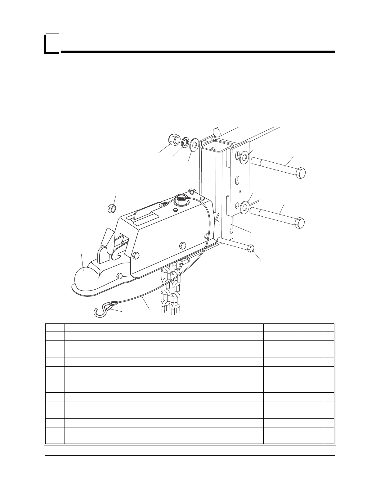
7. The hitch on the mill is adjustable. It should be raised or lowered to let the mill travel hori-
zontal to ground level. Adjust by removing the two mounting bolts. Then slide the hitch
tube up or down to new set of holes. Replace bolts and nuts.
DANGER! Be sure that the hitch and safety chains are
secure before towing the sawmill. Always connect the
break-away cable to the vehicle when towing the sawmill.
Failure to do so may result in serious personal injury and/or
severe machine damage.
DANGER! Make sure all brake and light connections have
been made and are working properly before towing the
sawmill. Failure to do so may result in serious personal
injury and/or severe machine damage. Make sure you have
complied with all applicable Federal, State and Local motor
vehicle safety laws.
DANGER! Chock the mill to prevent movement before
unhitching it from the towing vehicle. Failure to do so may
Other manuals for TRB-S
1
Table of contents
Other woodmizer Utility Vehicle manuals
Popular Utility Vehicle manuals by other brands

Cushman
Cushman Turf Truckster 84069 Parts & maintenance manual

Landoll
Landoll 900D Series Operator's manual

Westward
Westward Go-4 XTR Operator's manual

Club Car
Club Car Carryall I 1999 owner's manual

Etnyre
Etnyre Street Flusher operation, maintenance, parts and safety manual

Landoll
Landoll 340 Operator's manual