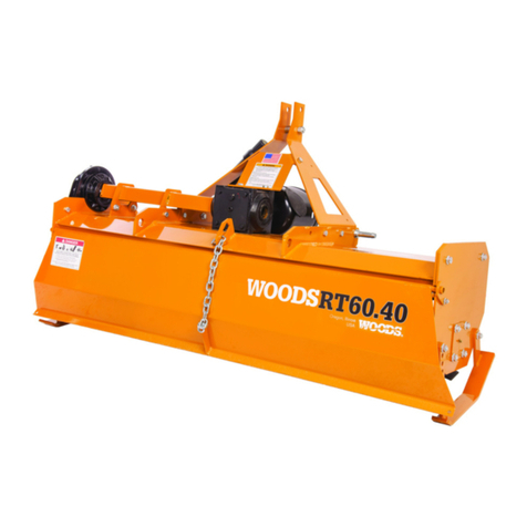
Woods RD6000 User manual

PN-52886 (Rev. 8/23/01)
REARMOUNT
RD6000
RD7200
RD8400
OPERATOR’S MANUAL

ii
TO THE DEALER:
Assembly and proper installation of this product is the responsibility of the WOODS dealer. Read manual
instructions and safety rules. Make sure all items on the Dealer’s Pre-Delivery and Delivery Check Lists in
the Operator’s Manual are completed before releasing equipment to the owner.
The dealer must complete the Warranty Registration included in this manual. Both dealer and customer must
sign the registration which certifies that all Dealer Check List items have been completed. The dealer is to
return the prepaid postage portion to Woods, give one copy to the customer, and retain one copy. Note:
Warranty credit is subject to this form being completed and returned.
TO THE OWNER:
Read this manual before operating your WOODS equipment. The information presented will prepare you to
do a better and safer job. Keep this manual handy for ready reference. Require all operators to read this
manual carefully andbecome acquainted with allthe adjustment andoperating procedures before attempting
to operate. Replacement manuals can be obtained from your dealer or, in the United States and Canada, by
calling 1-800-319-6637.
Theequipmentyouhavepurchased has been carefullyengineeredandmanufacturedto providedependable
and satisfactory use. Like all mechanical products, it will require cleaning and upkeep. Lubricate the unit as
specified. Observe all safety information in this manual and safety decals on the equipment.
For service, your authorized WOODS dealer has trained mechanics, genuine WOODS service parts, and the
necessary tools and equipment to handle all your needs.
Use only genuine WOODS service parts. Substitute parts will void the warranty and may not meet standards
required for safe and satisfactory operation. Record the model number and serial number of your equipment
in the spaces provided:
Model: Date of Purchase
Serial Number: (see Safety Decal section for location)
Provide this information to your dealer to obtain correct repair parts.
Throughout this manual, the term IMPORTANT is used to indicate that failure to observe can cause damage
to equipment. The terms CAUTION,WARNING and DANGER are used in conjunction with the Safety-Alert
Symbol, (a triangle with an exclamation mark), to indicate the degree of hazard for items of personal safety.
This Safety-Alert Symbol indicates a hazard and means
ATTENTION! BECOME ALERT! YOUR SAFETY IS INVOLVED!
Indicates an imminently hazardous situation that, if not avoided,
will result in death or serious injury.
Indicates a potentially hazardous situation that, if not avoided,
could result indeath orserious injury, and includeshazards that are
exposed when guards are removed
Indicates a potentially hazardous situation that, if not avoided, may
result in minor or moderate injury.
Indicates that failure to observe can cause damage to equipment.
Indicates helpful information.
CAUTION
WARNING
DANGER
IMPORTANT
NOTE
(Rev. 4/12/01)

1PN-52886 (4/97)
TABLE OF CONTENTS
INTRODUCTION ii...............................................
SPECIFICATIONS 1..............................................
GENERAL INFORMATION 2......................................
BOLT SIZE CHART 2.............................................
BOLT TORQUE CHART 3.........................................
SAFETY RULES 4--6............................................
SAFETY DECALS 7--8...........................................
OPERATION 9...................................................
OWNER SERVICE 14...........................................
DEALER SERVICE 18...........................................
TROUBLE SHOOTING 26--27.....................................
ASSEMBLY INSTRUCTIONS 28..................................
INDEX TO PARTS LISTS 33......................................
INDEX 41......................................................
WARRANTY Inside Back Cover....................................
RD6000, RD7200 & RD8400
SPECIFICATIONS
RD6000 RD7200 RD8400
3-Point Hitch Category 1 Category 1 Category 1.......................
Cutting Width 60” 72” 84”.........................
Cutting Height Range 1” -- 5-1/2” 1” -- 5-1/2” 1” -- 4-1/2”...............
Operating Weight with
Chain Shielding 605 lbs. 671 lbs. 770 lbs......................
Blade Speed (feet per minute) 16,950 16,800 16,700..........
Blade Speed (RPM) 3,083 2,570 2,179..................
Blades Spindles 3 3 3........................
Number of Blades 3 3 3......................
Universal Drive Series ASAE Cat. 3 ASAE Cat. 3 ASAE Cat. 3.............
Caster Wheels 3.25 x 10 3.25 x 10 3.25 x 10......................
Tractor PTO Speed RPM 540 540 540...............
Recommended Maximum
Tractor Horsepower 40 40 40....................
Mower Frame Thickness 8 GA 8 GA 8 GA..............
(Rev. 6/28/01)

PN-52886 (4/97)2
GENERAL INFORMATION
The purpose of this manual is to assist you in
operating and maintaining your mower. Read it
carefully. It furnishes information and instructions that
will help you achieve years of dependable perform-
ance. These instructions have been compiled from
extensive field experience and engineering data.
Some information may be general in nature due to
unknown and varying operating conditions. However,
through experience and these instructions, you
should be able to develop procedures suitable to your
particular situation.
The illustrations and data used in this manual were
current at the time of printing, but due to possible
inline production changes, your machine may vary
slightly in detail. We reserve the right to redesign and
change the machines as may be necessary without
notification.
WARNING
!Some illustrations in this manual show
the mower with safety shields removed to
provide a better view. The mower should
never be operated with any safety shield-
ing removed.
Throughout this manual, references are made to right
and left direction. These are determined by standing
behind the equipment facing the direction of forward
travel. Blade rotation is clockwise as viewed from the
top of the mower.
BOLT SIZE CHART
NOTE: Chart shows bolt thread sizes and corresponding head (wrench) sizes for standard SAE and Metric Bolts.
8MM 10MM 12MM 14MM 16MM 18MM
175150125100755025
IN
MM
17
65432
7/83/45/81/23/85/16
SAE Bolt Thread Sizes
Metric Bolt Thread Sizes

3PN-52886 (4/97)
BOLT TORQUE CHART
Always tighten hardware to these values unless a different torque value or tightening procedure is listed for a specific
application.
Fasteners must always be replaced with the same grade as specified in the manual parts list.
Always use the proper tool for tightening hardware: SAE for SAE hardware and Metric for metric hardware.
Make sure fastener threads are clean and you start thread engagement properly.
All torque values are given to specifications used on hardware defined by SAE J1701 & J1701M JUL96.
SAE Grade 2
(No Dashes) SAE Grade 5
(3 Radial Dashes) SAE Grade 8
(6 Radial Dashes)
SAE SERIES
TORQUE
CHART
A
SAE Bolt Head
Identification
A
MARKING ON HEAD
D
i
a
m
e
t
e
r
A
Wrench SAE 2 SAE 5 SAE 8
D
i
a
m
e
t
e
r
(
Inches
)
W
r
e
n
c
h
Size Lbs.-Ft. N-m Lbs.-Ft. N-m Lbs.-Ft. N-m
1/4 7/16” 6 8 10 13 14 18
5/16 1/2” 12 17 19 26 27 37
3/8 9/16” 23 31 35 47 49 67
7/16 5/8” 36 48 55 75 78 106
1/2 3/4” 55 75 85 115 120 163
9/16 13/16” 78 106 121 164 171 232
5/8 15/16” 110 149 170 230 240 325
3/4 1-1/8” 192 261 297 403 420 569
7/8 1-5/16” 306 416 474 642 669 907
11-1/2” 467 634 722 979 1020 1383
Metric
Grade 10.9
Metric
Grade 8.8
8.8 10.9
A
Metric Bolt Head
Identification
METRIC SERIES
TORQUE
CHART
D
i
a
m
e
t
e
r
A
COARSE THREAD FINE THREAD
D
i
a
m
e
t
e
r
A
D
i
ame
t
er
&
A
MARKING ON HEAD MARKING ON HEAD
D
i
ame
t
er
&
A
&
Thread Pitch Wrench Metric 8.8 Metric 10.9 Metric 8.8 Metric 10.9
&
Thread Pitch
(Millimeters)
W
r
e
n
c
h
Size N-m Lbs.-Ft. N-m Lbs.-Ft. N-m Lbs.-Ft. N-m Lbs.-Ft. (Millimeters)
6x1.0 10 mm 8 6 11 8 8 6 11 86x1.0
8 x 1.25 13 mm 20 15 27 20 21 16 29 22 8x1.0
10 x 1.5 16 mm 39 29 54 40 41 30 57 42 10 x 1.25
12 x 1.75 18 mm 68 50 94 70 75 55 103 76 12 x 1.25
14 x 2.0 21 mm 109 80 151 111 118 87 163 120 14 x 1.5
16 x 2.0 24 mm 169 125 234 173 181 133 250 184 16 x 1.5
18 x 2.5 27 mm 234 172 323 239 263 194 363 268 18 x 1.5
20 x 2.5 30 mm 330 244 457 337 367 270 507 374 20 x 1.5
22 x 2.5 34 mm 451 332 623 460 495 365 684 505 22 x 1.5
24 x 3.0 36 mm 571 421 790 583 623 459 861 635 24 x 2.0
30 x 3.0 46 mm 1175 867 1626 1199 1258 928 1740 1283 30 x 2.0
Typical Washer Installations
Nut
Bolt Lockwasher Flat
Washer
This manual suits for next models
2
Table of contents
Other Woods Lawn And Garden Equipment manuals
Popular Lawn And Garden Equipment manuals by other brands

Sunforce
Sunforce SOLAR user manual

GARDEN OF EDEN
GARDEN OF EDEN 55627 user manual

Goizper Group
Goizper Group MATABI POLMINOR instruction manual

Rain Bird
Rain Bird 11000 Series Operation & maintenance manual

Cub Cadet
Cub Cadet BB 230 brochure

EXTOL PREMIUM
EXTOL PREMIUM 8891590 Translation of the original user manual

Vertex
Vertex 1/3 HP Maintenance instructions

GHE
GHE AeroFlo 80 manual

Land Pride
Land Pride Post Hole Diggers HD25 Operator's manual

Yazoo/Kees
Yazoo/Kees Z9 Commercial Collection System Z9A Operator's & parts manual

Premier designs
Premier designs WindGarden 26829 Assembly instructions

Snapper
Snapper 1691351 installation instructions