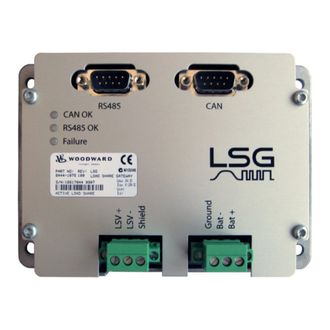
Woodward GW 4 User manual

37133E
Operation Manual
Software Version 2.0xxx
Manual 37133E
GW 4
Gateway / Interface Converter

Manual 37133E Gateway / Interface Converter - GW 4
Page 2/62 © Woodward
WARNING
Read this entire manual and all other publications pertaining to the work to be performed before instal-
ling, operating, or servicing this equipment. Practice all plant and safety instructions and precautions.
Failure to follow instructions can cause personal injury and/or property damage.
The engine, turbine, or other type of prime mover should be equipped with an overspeed (overtempera-
ture, or overpressure, where applicable) shutdown device(s), that operates totally independently of the
prime mover control device(s) to protect against runaway or damage to the engine, turbine, or other
type of prime mover with possible personal injury or loss of life should the mechanical-hydraulic gov-
ernor(s) or electric control(s), the actuator(s), fuel control(s), the driving mechanism(s), the linkage(s),
or the controlled device(s) fail.
Any unauthorized modifications to or use of this equipment outside its specified mechanical, electrical,
or other operating limits may cause personal injury and/or property damage, including damage to the
equipment. Any such unauthorized modifications: (i) constitute "misuse" and/or "negligence" within
the meaning of the product warranty thereby excluding warranty coverage for any resulting damage,
and (ii) invalidate product certifications or listings.
CAUTION
To prevent damage to a control system that uses an alternator or battery-charging device, make sure
the charging device is turned off before disconnecting the battery from the system.
Electronic controls contain static-sensitive parts. Observe the following precautions to prevent dam-
age to these parts.
•Discharge body static before handling the control (with power to the control turned off, contact a
grounded surface and maintain contact while handling the control).
•Avoid all plastic, vinyl, and Styrofoam (except antistatic versions) around printed circuit boards.
•Do not touch the components or conductors on a printed circuit board with your hands or with
conductive devices.
OUT-OF-DATE PUBLICATION
This publication may have been revised or updated since this copy was produced. To verify that you
have the latest revision, be sure to check the Woodward website:
http://www.woodward.com/pubs/current.pdf
The revision level is shown at the bottom of the front cover after the publication number. The latest
version of most publications is available at:
http://www.woodward.com/publications
If your publication is not there, please contact your customer service representative to get the latest
copy.
Important definitions
WARNING
Indicates a potentially hazardous situation that, if not avoided, could result in death or serious injury.
CAUTION
Indicates a potentially hazardous situation that, if not avoided, could result in damage to equipment.
NOTE
Provides other helpful information that does not fall under the warning or caution categories.
Woodward reserves the right to update any portion of this publication at any time. Information provided by Woodward is believed to be
correct and reliable. However, Woodward assumes no responsibility unless otherwise expressly undertaken.
© Woodward
All Rights Reserved.

Manual 37133E Gateway / Interface Converter - GW 4
© Woodward Page 3/62
Revision History
Rev. Date Editor Changes
NEW Tr Release
A 03-01-30 Tr Update
B 04-12-14 TP New format; GW 4/422 and GW 4/TTY added
C 05-09-20 TP Application restrictions and data assignment table added
D 07-03-29 TP Minor corrections
E 08-11-25 TE Minor corrections
NOTE
This manual will not be updated anymore. Refer to the GW 4 Packages manual 37360 for more recent
information about the GW 4 unit.
Content
CHAPTER 1. GENERAL INFORMATION..........................................................................................7
Related Documents..................................................................................................................................7
Overview ..................................................................................................................................................7
CHAPTER 2. ELECTROSTATIC DISCHARGE AWARENESS ..............................................................8
CHAPTER 3. HOUSING ................................................................................................................9
Dimensions ..............................................................................................................................................9
CHAPTER 4. CONNECTION ........................................................................................................10
Wiring Diagram GW4/232 ......................................................................................................................10
Wiring Diagram GW4/422 ......................................................................................................................11
Wiring Diagram GW4/TTY .....................................................................................................................12
Wiring Diagram GW4/485 ......................................................................................................................13
Wiring Diagram GW4/232/MDM02+LDP ...............................................................................................14
Wiring Diagram GW4/PRO ....................................................................................................................15
Power Supply .........................................................................................................................................16
Interfaces ...............................................................................................................................................16
Interface with Woodward Units....................................................................................................16
Interface with External Participants .............................................................................................17
CHAPTER 5. FUNCTIONAL DESCRIPTION ...................................................................................18
GW4/232 ................................................................................................................................................18
Functional Overview ....................................................................................................................18
GW 4/232/3964 [DK3964 (R) with Interpreter RK512] ................................................................18
GW 4/232/MOD [Modbus RTU Slave].........................................................................................19
GW 4/232/LDP [Leonhard Data Protocol] ...................................................................................20
GW4/422 ................................................................................................................................................21
Functional Overview ....................................................................................................................21
GW 4/422/3964 [DK3964 (R) with Interpreter RK512] ................................................................21
GW 4/422/MOD [Modbus RTU Slave].........................................................................................22
GW 4/422/LDP [Leonhard Data Protocol] ...................................................................................22

Manual 37133E Gateway / Interface Converter - GW 4
Page 4/62 © Woodward
GW4/TTY............................................................................................................................................... 23
Functional Overview.................................................................................................................... 23
GW 4/TTY/3964 [DK3964 (R) with Interpreter RK512] ............................................................... 23
GW 4/TTY/MOD [Modbus RTU Slave]........................................................................................ 24
GW 4/TTY/LDP [Leonhard Data Protocol] .................................................................................. 24
GW 4/485............................................................................................................................................... 25
Functional Overview.................................................................................................................... 25
GW 4/485/MOD [Modbus RTU Slave] ........................................................................................ 25
GW 4/485/LDP [Leonhard Data Protocol]................................................................................... 26
GW 4/232/MDM02+LDP........................................................................................................................ 26
Functional Overview.................................................................................................................... 26
GW 4/PRO............................................................................................................................................. 27
Functional Overview.................................................................................................................... 27
Remote Monitoring (Measured Value Display) ........................................................................... 27
Remote Control (Sending Set Point Values/Control Commands) .............................................. 27
Remote Configuration (Changing Non-Volatile Parameters)...................................................... 28
Notes ........................................................................................................................................... 28
Parameter.................................................................................................................................... 29
Machine Bus Monitoring For GW 4/xxx/MOD ............................................................................. 30
CHAPTER 6. DISPLAY AND CONTROL ELEMENTS ...................................................................... 31
Front Panel ............................................................................................................................................ 31
LEDs ...................................................................................................................................................... 32
LC Display ............................................................................................................................................. 32
Automatic Mode (First Display Line) ........................................................................................... 32
Automatic Mode (Second Display Line)...................................................................................... 32
Push Buttons ......................................................................................................................................... 33
CHAPTER 7. CONFIGURATION................................................................................................... 34
General Configuration Screens ............................................................................................................. 34
Data Transmission Mode....................................................................................................................... 36
Configuration Expansion (Sub-Units) .................................................................................................... 37
CHAPTER 8. TECHNICAL DATA ................................................................................................. 38
CHAPTER 9. DATA CONNECTION .............................................................................................. 39
Coupling via GW 4/232.......................................................................................................................... 39
Coupling via GW 4/422.......................................................................................................................... 40
Coupling via GW 4/TTY......................................................................................................................... 41
Coupling via GW 4/485.......................................................................................................................... 42
Coupling via GW 4/232/MDM02+LDP................................................................................................... 43
Coupling via GW 4/PRO........................................................................................................................ 44
APPENDIX A. PRACTICAL APPLICATIONS .................................................................................. 45
Structure of the GW 4............................................................................................................................ 45
The CAN Interface................................................................................................................................. 45
General Information..................................................................................................................... 45
Settings for Receiving CAN Messages ....................................................................................... 45
Size of the Receive Blocks.......................................................................................................... 46
Sending CAN Messages ............................................................................................................. 46
The Profibus Interface ........................................................................................................................... 48
Protocol 3964......................................................................................................................................... 48
Modbus .................................................................................................................................................. 48
Modbus Monitoring...................................................................................................................... 49
Sending Daten............................................................................................................................. 49
LDP Protocol.......................................................................................................................................... 49
Modem................................................................................................................................................... 49
Several GW4s at one CAN Bus............................................................................................................. 49

Manual 37133E Gateway / Interface Converter - GW 4
© Woodward Page 5/62
APPENDIX B. APPLICATION RESTRICTIONS ...............................................................................50
APPENDIX C. DATA ASSIGNMENT TABLE ..................................................................................51
Receiving Table of the GW 4 .................................................................................................................51
Transmission Table of the GW 4 ...........................................................................................................53
APPENDIX D. PARAMETER LIST ................................................................................................54
APPENDIX E. DECLARATION OF CONFORMITY ...........................................................................55
APPENDIX F. SERVICE OPTIONS ...............................................................................................57
Product Service Options ........................................................................................................................57
Returning Equipment for Repair ............................................................................................................57
Packing a Control ........................................................................................................................58
Return Authorization Number RAN .............................................................................................58
Replacement Parts.................................................................................................................................58
How to Contact Woodward ....................................................................................................................59
Engineering Services .............................................................................................................................60
Technical Assistance .............................................................................................................................61

Manual 37133E Gateway / Interface Converter - GW 4
Page 6/62 © Woodward
Illustrations and Tables
Illustrations
Figure 3-1: Dimensions GW4..................................................................................................................................................... 9
Figure 4-1: Wiring diagram GW4/232...................................................................................................................................... 10
Figure 4-2: Wiring diagram GW4/422...................................................................................................................................... 11
Figure 4-3: Wiring diagram GW4/TTY.................................................................................................................................... 12
Figure 4-4: Wiring diagram GW4/485...................................................................................................................................... 13
Figure 4-5: Wiring diagram GW4/MDM02.............................................................................................................................. 14
Figure 4-6: Wiring diagram GW4/PRO.................................................................................................................................... 15
Figure 4-7: Power supply.......................................................................................................................................................... 16
Figure 4-9: Interface - CAN bus............................................................................................................................................... 16
Figure 4-10: CAN bus - connection scheme............................................................................................................................. 17
Figure 4-11: Interfaces (external) ............................................................................................................................................. 17
Figure 6-1: Front panel............................................................................................................................................................. 31
Figure 9-1: Data coupling - GW4/232...................................................................................................................................... 39
Figure 9-2: Data coupling - GW4/422...................................................................................................................................... 40
Figure 9-3: Data coupling - GW4/TTY .................................................................................................................................... 41
Figure 9-4: Data coupling - GW4/485...................................................................................................................................... 42
Figure 9-5: Data coupling - GW4/MDM02 .............................................................................................................................. 43
Figure 9-6: Data coupling - GW4/PRO .................................................................................................................................... 44
Tables
Table 1-1: Manual - overview..................................................................................................................................................... 7
Table 4-1: Power supply- terminal assignment......................................................................................................................... 16
Table 4-3: Interfaces (external) - terminal assignment ............................................................................................................. 17

Manual 37133E Gateway / Interface Converter - GW 4
© Woodward Page 7/62
Chapter 1.
General Information
Related Documents
≡≡≡≡≡≡≡≡≡≡≡≡≡≡≡≡≡≡≡≡≡≡≡≡≡
Type English German
Gateway GW4
GW 4 – Manual this manual Ö37133C GR37133C
Table 1-1: Manual - overview
Overview
≡≡≡≡≡≡≡≡≡≡≡≡≡≡≡≡≡≡≡≡≡≡≡≡≡
This operation manual describes the following types of the Gateway GW 4:
•GW 4/232
•GW 4/422
•GW 4/TTY
•GW 4/485
•GW 4/232/MDM02+LDP
•GW 4/PRO
Please refer to the name plate of your Gateway GW 4 to establish the correct type. The different units allow dif-
ferent protocols. They depend on the used hardware.
Intended Use The control must only be operated according to the guidelines described in this manual. The pre-
requisite for a proper and safe operation of the product is correct transportation, storage, and installation as well
as careful operation and maintenance.
NOTE
This manual has been developed for an control fitted with all available options. Inputs/outputs, func-
tions, configuration screens, and other details described, which do not exist on your control, may be
ignored.
The present manual has been prepared to enable the installation and commissioning of the control.
Due to the large variety of parameter settings, it is not possible to cover every combination. The ma-
nual is therefore only a guide. In case of incorrect entries or a total loss of functions, the default set-
tings may be taken from the enclosed list of parameters.

Manual 37133E Gateway / Interface Converter - GW 4
Page 8/62 © Woodward
Chapter 2.
Electrostatic Discharge Awareness
All electronic equipment is static-sensitive, some components more than others. To protect these components
from static damage, you must take special precautions to minimize or eliminate electrostatic discharges.
Follow these precautions when working with or near any control.
1. Before doing maintenance on the electronic control, discharge the static electricity on your body to
ground by touching and holding a grounded metal object (pipes, cabinets, equipment, etc.).
2. Avoid the build-up of static electricity on your body by not wearing clothing made of synthetic materials.
Wear cotton or cotton-blend materials as much as possible because these do not store static electric
charges as easily as synthetics.
3. Keep plastic, vinyl, and Styrofoam materials (such as plastic or Styrofoam cups, cigarette packages, cello-
phane wrappers, vinyl books or folders, plastic bottles, etc.) away from the control, modules, and work
area as much as possible.
4. Opening the control cover may void the unit warranty.
Do not remove the printed circuit board (PCB) from the control cabinet unless absolutely necessary. If
you must remove the PCB from the control cabinet, follow these precautions:
•Ensure that the device is completely voltage-free (all connectors have to be disconnected).
•Do not touch any part of the PCB except the edges.
•Do not touch the electrical conductors, connectors, or components with conductive devices or with
bare hands.
•When replacing a PCB, keep the new PCB in the plastic antistatic protective bag it comes in until you
are ready to install it. Immediately after removing the old PCB from the control cabinet, place it in the
antistatic protective bag.
CAUTION
To prevent damage to electronic components caused by improper handling, read and observe the pre-
cautions in Woodward manual 82715, Guide for Handling and Protection of Electronic Controls, Printed
Circuit Boards, and Modules.

Manual 37133E Gateway / Interface Converter - GW 4
© Woodward Page 9/62
Chapter 3.
Housing
Dimensions
≡≡≡≡≡≡≡≡≡≡≡≡≡≡≡≡≡≡≡≡≡≡≡≡≡
Housing Typ APRANORM DIN 43700
Dimensions 96 × 72 × 130 mm
Front panel cutout 91 × 67 mm
Wiring Screw-type terminals, depending on connector 1,5 mm² or 2,5 mm²
Protection class IP 21, from front IP45
Weight depending on version, approx. 500 g
2003-01-23 | GW 4 Dimensions w4ww-0403-ab.skf
50
130
96
8
90
130
72
65
27 35
- Back view -
connecting terminals
depending on the existing hardware
Bottom view
Back plate mounting
optionally
Front view
Figure 3-1: Dimensions GW4

Manual 37133E Gateway / Interface Converter - GW 4
Page 10/62 © Woodward
Chapter 4.
Connection
Wiring Diagram GW4/232
≡≡≡≡≡≡≡≡≡≡≡≡≡≡≡≡≡≡≡≡≡≡≡≡≡
24 Vdc
0 Vdc
CAN bus (CAL)
Interface
RS-232
2004-10-04 | GW 4-232 Wiring Diagram w4rs232ww-0445-ap.skf
CTS
Y4
RxD
GND
RTS
Subject to technical modifications.
87 Y1 Y2 Y3
Back view
1
X1 X5
CAN
16
Y1 Y5
RS232
TxD
CAN-L
CAN-H
GND
Termination
X5X2X1Y5 X4X3
Note:
The termination must be
effected with a resistor
which corresponds to the
wave impedance of the
used cable (e. g. 120 Ohm)
GW 4 - RS-232 (GW 4/232)
Figure 4-1: Wiring diagram GW4/232

Manual 37133E Gateway / Interface Converter - GW 4
© Woodward Page 11/62
Wiring Diagram GW4/422
≡≡≡≡≡≡≡≡≡≡≡≡≡≡≡≡≡≡≡≡≡≡≡≡≡
24 Vdc
0 Vdc
CAN bus (CAL)
Interface
RS-422
2004-10-04 | GW 4-422 Wiring Diagram w4rs422ww-0445-ap.skf
A' / Rx-
(Z inverted)
Y4
B / Tx+
(A non-inverted)
GND
A / Tx-
(B inverted)
Subject to technical modifications.
87 Y1 Y2 Y3
Back view
1
X1 X5
CAN
16
Y1 Y5
RS-422
B' / Rx+
(Y non-inverted)
CAN-L
CAN-H
GND
Termination
X5X2X1Y5 X4X3
Note:
The termination must be
effected with a resistor
which corresponds to the
wave impedance of the
used cable (e. g. 120 Ohm)
GW 4 - RS-422 (GW 4/422)
Transmitter
Receiver
Figure 4-2: Wiring diagram GW4/422

Manual 37133E Gateway / Interface Converter - GW 4
Page 12/62 © Woodward
Wiring Diagram GW4/TTY
≡≡≡≡≡≡≡≡≡≡≡≡≡≡≡≡≡≡≡≡≡≡≡≡≡
24 Vdc
0 Vdc
CAN bus (CAL)
Interface
TTY
2004-10-04 | GW 4-TTY Wiring Diagram w4rsTTYww-0445-ap.skf
TxD-
Y4
RxD+
NC
RxD-
Subject to technical modifications.
87 Y1 Y2 Y3
Back view
1
X1 X5
CAN
16
Y1 Y5
TTY
TxD+
CAN-L
CAN-H
GND
Termination
X5X2X1Y5 X4X3
Note:
The termination must be
effected with a resistor
which corresponds to the
wave impedance of the
used cable (e. g. 120 Ohm)
GW 4 - TTY (GW 4/TTY)
Figure 4-3: Wiring diagram GW4/TTY

Manual 37133E Gateway / Interface Converter - GW 4
© Woodward Page 13/62
Wiring Diagram GW4/485
≡≡≡≡≡≡≡≡≡≡≡≡≡≡≡≡≡≡≡≡≡≡≡≡≡
24 Vdc
0 Vdc
CAN bus (CAL)
Interface
RS485
2003-01-23 | GW 4-485 Wiring Diagram w4rs485ww-0403-ap.skf
Y4
B
Transmitter
and
Receiver
(inverted)
GND
Subject to technical modifications.
87 Y1 Y2 Y3
Back view
1
X1 X5
16
Y1 Y5
CAN-L
CAN-H
GND
Termination
A
X5X2X1Y5 X4X3
Note:
The termination must be
effected with a resistor
which corresponds to the
wave impedance of the
used cable (e. g. 120 Ohm)
(non-inverted)
GW 4 - RS485 (GW 4/485)
CAN RS485
Figure 4-4: Wiring diagram GW4/485

Manual 37133E Gateway / Interface Converter - GW 4
Page 14/62 © Woodward
Wiring Diagram GW4/232/MDM02+LDP
≡≡≡≡≡≡≡≡≡≡≡≡≡≡≡≡≡≡≡≡≡≡≡≡≡
24 Vdc
0 Vdc
CAN bus (CAL)
Interface
RS232
2004-08-30 | GW 4-MDM02 Wiring Diagram w4mdm02ww-0436-ap.skf
CTS
Y4
RxD
GND
RTS
Subject to technical modifications.
87 Y1 Y2 Y3
Back view
1
X1 X5
CAN
16
Y1 Y5
RS232
TxD
CAN-L
CAN-H
GND
Termination
X5X2X1Y5 X4X3
Note:
The termination must be
effected with a resistor
which corresponds to the
wave impedance of the
used cable (e. g. 120 Ohms)
GW 4 - Modem (GW 4/MDM02)
Figure 4-5: Wiring diagram GW4/MDM02

Manual 37133E Gateway / Interface Converter - GW 4
© Woodward Page 15/62
Wiring Diagram GW4/PRO
≡≡≡≡≡≡≡≡≡≡≡≡≡≡≡≡≡≡≡≡≡≡≡≡≡
24 Vdc
0 Vdc
CAN bus (CAL)
Profibus DP
slave
2003-01-23 | GW 4-PRO Wiring Diagram w4proww-0403-ap.skf
Y5
B-Line
A-Line
GND
+5 V
Screen
Subject to technical modifications.
87 Y4Y3Y2Y1
Back view
Note:
The Profi bus connection
has to be terminated
according to the
Profi bus specifications.
1
X1 X5
16
Y1 Y6
CAN-L
CAN-H
GND
Termination
RTS
X5X2X1 X4X3Y6
Note:
The termination must be
effected with a resistor
which corresponds to the
wave impedance of the
used cable (e. g. 120 Ohm)
GW 4 - Profibus DP (GW 4/PRO)
CAN Profibus DP
Figure 4-6: Wiring diagram GW4/PRO

Manual 37133E Gateway / Interface Converter - GW 4
Page 16/62 © Woodward
Power Supply
≡≡≡≡≡≡≡≡≡≡≡≡≡≡≡≡≡≡≡≡≡≡≡≡≡
18 to 30 Vdc
7 8
0 V
18 to 30 Vdc
Power supply
Figure 4-7: Power supply
Terminal Description Amax
7 0 V reference potential 2.5 mm²
8 18 to 30 Vdc, max. 10 W 2.5 mm²
Table 4-1: Power supply- terminal assignment
Interfaces
≡≡≡≡≡≡≡≡≡≡≡≡≡≡≡≡≡≡≡≡≡≡≡≡≡
Interface with Woodward Units
The interface with connected Woodward units is established via the CAN bus.
Terminal Description
X1 X2 X3 X4 X5
CAN-H CAN-L GND CAN-H CAN-L CAN bus
GND
CAN-H
CAN-L
X1 X2 X3 X4 X5
Interface
CAN bus
Termination
Tabee 4-2: CAN interface (Woodward) - terminal assignment Figure 4-8: Interface
NOTE
Please note that the CAN bus must be terminated with an impedance which corresponds to the wave
impedance of the cable (e.g. 120 Ohm).
Interface
CAN bus
CAN-H
CAN-L
GND
Shield
2 MOhm
3.3 uF
1000 Vac
C B A
Figure 4-9: Interface - CAN bus

Manual 37133E Gateway / Interface Converter - GW 4
© Woodward Page 17/62
The following must be noted to ensure trouble-free operation of the CAN bus:
•The maximum bus length must not exceed 250 meters.
•The bus must be terminated at each end with terminating resistors that correspond to the wave imped-
ance of the bus cable (approx. 120 Ω).
•The structure of the bus must be linear. Dead-end feeders are not permissible.
•Shielded "Twisted-Pairs" are preferable for use as bus cables (e.g.: Lappkabel Unitronic LIYCY (TP)
2×2×0.25, UNITRONIC-Bus LD 2×2×0.22).
•The bus cable must not be routed in the vicinity of power lines.
GND
CAN-L
CAN-H
GND
GND
CAN-L
CAN-H
CAN-L
CAN-H
CAN-L
CAN-H
GW 4
Termination
Te r m i n a t i o n
resistor
Note:
The termination has to be
performed with a resisitance,
which corresponds to the
impedance of the used cable
(e.g 120 Ohms)
e.g. GCP-30 e.g. GCP-30
Termination
Te r mi n a t i on
resistor
X1 X2 X3 X4 X5 X5X4X3X2X1 X5X4X3X2X1Y2 Y3 Y4 Y5 Y6Y1
required interface, e.g.
RS-232
RS-485
Modbus RTU Slave
CAN bus
Profibus DP
Figure 4-10: CAN bus - connection scheme
NOTE
The CAN bUS terminals X1 and X4 as well as X2 and X5 are wired internally.
Interface with External Participants
The interface with connected external participants may be established via several bus systems or interface proto-
cols.
Y3Y1 Y2 Y4 Y5
Interface
RS-232 interface
GND
RTS
RxD
CTS
TxD
Interface
RS-485 interface
MOD bus RTU slave
B (inverted)
A (non-inverted)
GND
Interface
CAN bus
Termination
GND
CAN-H
CAN-L
Interface
Profi bus DP
Screen
A-Line
GND
+5 V
Y6
B-Line
RTS
Y1 Y2 Y3 Y4 Y5 Y1 Y2 Y3 Y4 Y5 Y1 Y2 Y3 Y4 Y5
The transmitter drives the current.
Interface
TTY interface
RxD -
RxD +
NC
TxD +
TxD -
GND
Interface
RS-422 interface
B / Tx+
(A non-inverted)
A / Tx-
(B inverted)
A' / Rx-
(Z inverted)
B' / Rx+
(Y non-inverted)
Y1 Y2 Y3 Y4 Y5Y1 Y2 Y3 Y4 Y5
Figure 4-11: Interfaces (external)
Terminal Description
Y1 Y2 Y3 Y4 Y5
RxD RTS GND CTS TxD RS-232
B / Tx+ A / Tx- GND A' / Rx- B' / Rx+ RS-422
RxD+ RxD- NC TxD- TxD+ TTY
GND B A RS-485, Modbus RTU Slave
CAN-H CAN-L GND CAN-H CAN-L CAN bus
Y1 Y2 Y3 Y4 Y5 Y6
Shield +5 V GND A line B line RTS Profibus DP (use the file
WOOD_V13.GSD)
Table 4-3: Interfaces (external) - terminal assignment

Manual 37133E Gateway / Interface Converter - GW 4
Page 18/62 © Woodward
Chapter 5.
Functional Description
ATTENTION
The supply voltage (24 Vdc) for the GW 4 Gateway must not be connected directly to the engine's
starter battery.
The following occurs if the unit is started by remote starting via the GW 4 Gateway from the control
room/PLC: If the starter is energized, the supply voltage of the GW 4 Gateway can fall below below
18 Vdc. As a result, the GW 4 Gateway is reset and therefore issues a remote stop. A new starting pro-
cedure is then initiated and the same happens again. This procedure will repeats continuously.
Because there is a delay in the time taken by the GCP/AMG to detect an interface error (i.e. the error
must be present for several seconds before the GCP/AMG is triggered), the fact that the GW 4 Gateway
was momentarily reset is not detected as an error.
GW4/232
≡≡≡≡≡≡≡≡≡≡≡≡≡≡≡≡≡≡≡≡≡≡≡≡≡
Functional Overview
The following protocols are implemented in this GW 4 (interface converter from CAN bus to RS-232 interface):
•Siemens DK3964 (R) with interpreter RK512 (can be switched on/off) GW 4/232/3964
•Modbus RTU slave (only two participants are possible) GW 4/232/MOD
•Leonhard data protocol GW 4/232/LDP
The following functions are supported with this:
•Remote monitoring: display of all measured values
•Remote control: data transmission
GW 4/232/3964 [DK3964 (R) with Interpreter RK512]
Interface Data
Data Character length 8 bit
Stop bit 1 bit
Parity bit 1 bit with configurable parity (even/odd/no)
Data format 16 bit binary values
Transmission rates 1,200 / 2,400 / 4,800 / 9,600 / 19,200 / 31,250 Bauds, configurable. The da-
ta records are transmitted cyclically.
Procedure DK3964/3964R with interpreter RK512
Procedure interpreter RK 512 Refer to the Siemens documents to protocol 3964.

Manual 37133E Gateway / Interface Converter - GW 4
© Woodward Page 19/62
Remote Monitoring (Measured Value Display)
GW 4 can transfer more data than can be handled in a DK 3964 telegram. This is why the master can request data
packets of an individual length from GW 4. Refer to Appendix C on page 51 for data word assignment.
NOTE
Bit 15 in DW 100 is set, if the GW 4 receives data from the CAN bus. (It may be used for CAN interface
monitoring).
Remote Control (Sending Set Point Values/Control Commands)
Three words are sent cyclically from the GW 4 Gateway to each unit connected that can be controlled remotely.
These usually comprise:
•Set point power
•Set point power factor
•Word containing control bits
The relevant words must be sent to the corresponding data blocks for transmission. T Refer to Appendix C on
page 51 for data word assignment.
The meaning of the data depends on the lower-level unit and is contained in the manual of this unit.
GW 4/232/MOD [Modbus RTU Slave]
Interface Data
Data Character length 8 bit
Stop bit 1 bit
Parity bit no parity
Data format 16 bit binary values
Transmission rates 1,200 / 2,400 / 4,800 / 9,600 / 19,200 / 38,400 Bauds
Procedure Modbus RTU Slave
A maximum of 20 words can be read or 10 words can be written with one command. Modbus function codes 03,
04, 06 and 16 are supported.
NOTE
Only two participants (1 Master and 1 Slave) can be connected for Modbus with interface RS-232.
Remote Monitoring (Measured Value Display)
Refer to Appendix C on page 51 for data word assignment.
NOTE
Bit 15 in the addresses 0, 70, … (always first address of the data block) is set, if the GW 4 receives data
from the CAN bus. (It may be used for CAN interface monitoring).

Manual 37133E Gateway / Interface Converter - GW 4
Page 20/62 © Woodward
Remote Control (Sending Set Point Values/Control Commands)
Three words are sent cyclically from the GW 4 Gateway to each unit connected that can be controlled remotely.
These usually comprise:
•Set point power
•Set point power factor
•Word containing control bits
The relevant words must be sent to the corresponding data blocks for transmission. Refer to Appendix C on
page 51 for data word assignment.
The meaning of the data depends on the lower-level unit and is contained in the manual of this unit.
GW 4/232/LDP [Leonhard Data Protocol]
The Leonhard Data Protocol is an ASCII protocol for connecting to a PC via a serial port. It allows remote con-
trol (transmission of set point values/control commands), remote monitoring (visualization of measured data),
and remote configuration (modification of unit parameters). This protocol is normally only used by the LeoPC1
program. Details about this protocol are available upon request.
The baud rate of this communications link can be configured to 38,400 or 9,600 Bauds. Please note that you have
to configure the same baud rate in LeoPC1.
NOTE
The GW 4/232/LDP may be operated with a modem, which does not require external configuration. We
recommend the following modems:
•Analog connection: Phoenix PSI-Data/Fax-Modem/RS232
•GSM connection: INSYS GSM 4.0
It is possible for both, to dispatch a fax or a short message by the means of a discrete input.
Table of contents
Other Woodward Gateway manuals