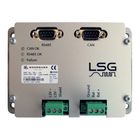
Woodward 8273-587 User manual

Product Manual 35012
(Revision New, 6/2015)
Original Instructions
Intelligent Gateway
Control Part Numbers 8273-587
Installation and Operation Manual

General
Precautions
Read this entire manual and all other publications pertaining to the work to be
performed before installing, operating, or servicing this equipment.
Practice all plant and safety instructions and precautions.
Failure to follow instructions can cause personal injury and/or property damage.
Revisions
This publication may have been revised or updated since this copy was produced.
To verify that you have the latest revision, check manual
26455
, Customer
Publication Cross Reference and Revision Status & Distribution Restrictions, on
the publications page of the Woodward website:
www.woodward.com/publications
The latest version of most publications is available on the publications page. If
your publication is not there, please contact your customer service representative
to get the latest copy.
Proper Use
Any unauthorized modifications to or use of this equipment outside its specified
mechanical, electrical, or other operating limits may cause personal injury and/or
property damage, including damage to the equipment. Any such unauthorized
modifications: (i) constitute "misuse" and/or "negligence" within the meaning of
the product warranty thereby excluding warranty coverage for any resulting
damage, and (ii) invalidate product certifications or listings.
Translated
Publications
If the cover of this publication states "Translation of the Original Instructions"
please note:
The original source of this publication may have been updated since this
translation was made. Be sure to check manual
26455
, Customer Publication
Cross Reference and Revision Status & Distribution Restrictions, to verify whether
this translation is up to date. Out-of-date translations are marked with . Always
compare with the original for technical specifications and for proper and safe
installation and operation procedures.
Revisions—Changes in this publication since the last revision are indicated by a black line
alongside the text.
Woodward reserves the right to update any portion of this publication at any time. Information provided by Woodward is
believed to be correct and reliable. However, no responsibility is assumed by Woodward unless otherwise expressly
undertaken.
Manual 35012
Copyright © Woodward 2015
All Rights Reserved

Manual 35012 Intelligent Gateway
Woodward 1
Contents
WARNINGS AND NOTICES............................................................................4
ELECTROSTATIC DISCHARGE AWARENESS ..................................................5
REGULATORY COMPLIANCE ........................................................................6
CHAPTER 1. GENERAL INFORMATION.........................................................10
Introduction...........................................................................................................10
CHAPTER 2. POWER SUPPLY BOARD.........................................................12
CHAPTER 3. CPU A5200 AND CAN BOARD ..............................................15
Intelligent Gateway General Description ..............................................................15
SmartCore CPU A5200 board..............................................................................16
CAN Communications Board ...............................................................................18
Intelligent Gateway Module Configuration............................................................20
Hardware Specifications.......................................................................................23
SmartCore CPU A5200 Board Operation.............................................................27
CHAPTER 4. SPECIFICATIONS ....................................................................41
CHAPTER 5. INSTALLATION........................................................................44
Introduction...........................................................................................................44
General Installation...............................................................................................44
Shipping Carton....................................................................................................44
Mounting...............................................................................................................45
I/O Terminal Blocks ..............................................................................................47
CAN Terminal Blocks ...........................................................................................48
Grounding.............................................................................................................49
Input Power ..........................................................................................................50
CAN Cable Wiring ................................................................................................53
Shields and Grounding .........................................................................................53
Non-Marine Enclosure Application Information ....................................................60
General Enclosure Application Information ..........................................................62
CHAPTER 6. GENERAL START-UP AND OPERATING INSTRUCTIONS.............67
General.................................................................................................................67
Application Guidelines ..........................................................................................67
CHAPTER 7. MAINTENANCE.......................................................................69
CHAPTER 8. DIAGNOSTICS AND TROUBLESHOOTING..................................70
Status Indicators (LEDs).......................................................................................70
Troubleshooting Guide .........................................................................................73
CHAPTER 9. PRODUCT SUPPORT AND SERVICE OPTIONS...........................74
Product Support Options ......................................................................................74
Product Service Options.......................................................................................74
Returning Equipment for Repair...........................................................................75
Replacement Parts ...............................................................................................76
Engineering Services............................................................................................76
Contacting Woodward’s Support Organization ....................................................76
Technical Assistance............................................................................................77
APPENDIX A. ACRONYMS AND GLOSSARY OF TERMS.................................78
Acronyms..............................................................................................................78
Glossary of Terms ................................................................................................78
REVISION HISTORY....................................................................................79

Intelligent Gateway Manual 35012
2 Woodward
DECLARATIONS .........................................................................................80
ILLUSTRATIONS AND TABLES
Figure 2-1. Intelligent Gateway Power Supply Board...........................................12
Figure 2-2. Discrete Output Wiring Example........................................................14
Figure 3-1. SmartCore CPU A5200 Board Connectors........................................16
Figure 3-2. Block Diagram -- Intelligent Gateway SmartCore CPU A5200
Board ...............................................................................................17
Figure 3-3. Eight Channel CAN Communication Board .......................................18
Figure 3-4. Block Diagram – Intelligent Gateway 8-Channel CAN Board............19
Figure 3-5. SmartCore CPU A5200 Communications Ports (SIO1, SIO2) ..........21
Figure 3-6. CPU Service Port (mini-DIN6F) .........................................................22
Figure 3-7. CAN Communication Ports ................................................................22
Figure 3-8 Network Cable Lengths.......................................................................22
Figure 3-9. MPU Minimum Input Magnitude in Vrms ...........................................23
Figure 3-10. MPU Maximum Input Magnitude in Vrms ........................................24
Figure 3-11. MPU Typical Input Impedance Magnitude and Phase.....................24
Figure 3-12. Wiring Example–MPU Interface to the SmartCore Board................28
Figure 3-13. Wiring Example–Open Collector Proximity Probe to the SmartCore
CPU A5200 Board ...........................................................................28
Figure 3-14a. Wiring Example–4–20 mA Input Interface to the SmartCore CPU
A5200 Board....................................................................................29
Figure 3-14b. Wiring Example–4–20 mA Input Interface using External Loop
Power...............................................................................................30
Figure 3-15. Wiring Example–Analog Output Interface to the SmartCore CPU
A5200 Board....................................................................................30
Figure 3-16. Wiring Example–Actuator Output Interface to the SmartCore CPU
A5200 Board....................................................................................31
Figure 3-17. Wiring Example–Discrete Input Interface to the SmartCore CPU
A5200 Board....................................................................................32
Figure 3-18. Serial #1–RS-232 Pinouts................................................................33
Figure 3-19. Serial #1–RS-422 Pinouts................................................................33
Figure 3-20. Serial #1–RS-485 Pinouts................................................................34
Figure 3-21. Serial #2–RS-232 Pinouts................................................................34
Figure 3-22. Serial #2–RS-422 Pinouts................................................................35
Figure 3-23. Serial #2–RS-485 Pinouts................................................................35
Figure 3-24. Wiring Example–RS-232 Interface to the SmartCore CPU A5200
Board ...............................................................................................36
Figure 3-25. Wiring Example–RS-422 Interface to the SmartCore CPU A5200
Board ...............................................................................................36
Figure 3-26. Wiring Example–RS-485 Interface to the SmartCore CPU A5200
Board ...............................................................................................36
Figure 3-27. Wiring Example–Alternate Multipoint Wiring....................................36
Figure 5-1. Optional RV1 Isolation Kit Installation................................................46
Figure 5-2. Screw Connection Terminal Block Used on A5200 SmartCore
Board ...............................................................................................47
Figure 5-3. Spring Clamp Terminal Block ............................................................47
Figure 5-4. Wiring Fixed Terminal ........................................................................48
Figure 5-5. Input Power Wiring.............................................................................51
Figure 5-6. Input Power Wiring Diagram ..............................................................52
Figure 5-7. Spring Clamp Terminal Block ............................................................53
Figure 5-8. Ethernet Ports ....................................................................................55
Figure 5-9. CPU Service Port (mini-DIN6F) .........................................................56
Figure 5-10. CAN Communication Ports ..............................................................57
Figure 5-11. Descriptions of Main Cabinet Cabling Options ................................63
Figure 8-1. CAN Ports #1–#4 Status and Fault Indicators ...................................70

Manual 35012 Intelligent Gateway
Woodward 3
Table 1-1. CAN Network Compatibility.................................................................11
Table 1-2. Gateway Compatibility ........................................................................11
Table 3-1. SmartCore CPU A5200 LEDs. ............................................................20
Table 3-2. Ethernet Port Pinout............................................................................21
Table 3-3. Network Speed vs. Cable Length........................................................22
Table 3-4. Digital Speed Sensors.........................................................................23
Table 3-5. MPU Inputs..........................................................................................23
Table 3-6. Proximity Probe Inputs ........................................................................25
Table 3-7. Analog Inputs ......................................................................................25
Table 3-8. Analog outputs ....................................................................................26
Table 3-9. Actuator Outputs .................................................................................26
Table 3-10. Discrete Inputs ..................................................................................26
Table 3-11 Serial I/O Channels ............................................................................27
Table 3-12. SmartCore CPU A5200 Failure Codes .............................................38
Table 5-1. Power Supply Requirements...............................................................52
Table 5-2. Ethernet Port Pinout............................................................................56
Table 5-3. Suggested CAN wiring colors .............................................................57
Table 5-4. Network Speed vs. Cable length and Type.........................................57
Table 5-5. CAN Cable Specifications ...................................................................58
Table 5-6. Recommended Cable for RTCnet and LINKnet-HT............................59
Table 5-7. Approved Cables.................................................................................59
Table 5-8 Field Devices and Status .....................................................................64
Table 8-1. Ethernet LEDs and Status...................................................................71
Table 8-2. CAN PORT STATUS Indicators..........................................................71
Table 8-3. CAN FAULT Indicators........................................................................72
Table 8-4. Gateway Unit Fault Codes ..................................................................72
The following are trademarks of Woodward, Inc.:
GAP
LINKnet
MicroNet
RTCnet
The following are trademarks of their respective companies:
DeviceNet (Open DeviceNet Vendor Association, Inc. [ODVA])
VxWorks (Wind River Systems, Inc.)

Intelligent Gateway Manual 35012
4 Woodward
Warnings and Notices
Important Definitions
This is the safety alert symbol. It is used to alert you to potential
personal injury hazards. Obey all safety messages that follow this
symbol to avoid possible injury or death.
DANGER—indicates a hazardous situation which, if not avoided, will result
in death or serious injury.
WARNING—indicates a hazardous situation which, if not avoided, could
result in death or serious injury.
CAUTION—indicates a hazardous situation which, if not avoided, could
result in minor or moderate injury.
NOTICE—indicates a hazard that could result in property damage only
(including damage to the control).
IMPORTANT—designates an operating tip or maintenance suggestion.
Overspeed /
Overtemperature /
Overpressure
The engine, turbine, or other type of prime mover should be
equipped with an overspeed shutdown device to protect against
runaway or damage to the prime mover with possible personal injury,
loss of life, or property damage.
The overspeed shutdown device must be totally independent of the
prime mover control system. An overtemperature or overpressure
shutdown device may also be needed for safety, as appropriate.
Personal Protective
Equipment
The products described in this publication may present risks that
could lead to personal injury, loss of life, or property damage. Always
wear the appropriate personal protective equipment (PPE) for the job
at hand. Equipment that should be considered includes but is not
limited to:
Eye Protection
Hearing Protection
Hard Hat
Gloves
Safety Boots
Respirator
Always read the proper Material Safety Data Sheet (MSDS) for any
working fluid(s) and comply with recommended safety equipment.
Start-up
Be prepared to make an emergency shutdown when starting the
engine, turbine, or other type of prime mover, to protect against
runaway or overspeed with possible personal injury, loss of life, or
property damage.
Automotive
Applications
On- and off-highway Mobile Applications: Unless Woodward's control
functions as the supervisory control, customer should install a
system totally independent of the prime mover control system that
monitors for supervisory control of engine (and takes appropriate
action if supervisory control is lost) to protect against loss of engine
control with possible personal injury, loss of life, or property damage.

Manual 35012 Intelligent Gateway
Woodward 5
Battery Charging
Device
To prevent damage to a control system that uses an alternator or
battery-charging device, make sure the charging device is turned off
before disconnecting the battery from the system.
Electrostatic Discharge Awareness
Electrostatic
Precautions
Electronic controls contain static-sensitive parts. Observe the
following precautions to prevent damage to these parts:
Discharge body static before handling the control (with power to
the control turned off, contact a grounded surface and maintain
contact while handling the control).
Avoid all plastic, vinyl, and Styrofoam (except antistatic versions)
around printed circuit boards.
Do not touch the components or conductors on a printed circuit
board with your hands or with conductive devices.
To prevent damage to electronic components caused by improper
handling, read and observe the precautions in Woodward manual
82715
, Guide for Handling and Protection of Electronic Controls,
Printed Circuit Boards, and Modules.
Follow these precautions when working with or near the control.
1. Avoid the build-up of static electricity on your body by not wearing clothing
made of synthetic materials. Wear cotton or cotton-blend materials as much
as possible because these do not store static electric charges as much as
synthetics.
2. Do not remove the printed circuit board (PCB) from the control cabinet
unless absolutely necessary. If you must remove the PCB from the control
cabinet, follow these precautions:
Do not touch any part of the PCB except the edges.
Do not touch the electrical conductors, the connectors, or the
components with conductive devices or with your hands.
When replacing a PCB, keep the new PCB in the plastic antistatic
protective bag it comes in until you are ready to install it. Immediately
after removing the old PCB from the control cabinet, place it in the
antistatic protective bag.

Intelligent Gateway Manual 35012
6 Woodward
Regulatory Compliance
European Compliance for CE Marking:
These listings are limited only to those units bearing the CE Marking.
EMC Directive: Declared to 2004/108/EC COUNCIL DIRECTIVE of 15
December 2004 on the approximation of the laws of the
Member States relating to electromagnetic compatibility
and all applicable amendments.
ATEX - Potentially Declared to 94/9/EC COUNCIL DIRECTIVE of 23 March
Explosive 1994 on the approximation of the laws of the Member
Atmospheres States concerning equipment and protective systems
Directive: intended for use in potentially explosive atmospheres.
Zone 2, Category 3, Group II G, Ex nA IIC T4 X Gc
Other European and International Compliance:
IECEx: Ex nA IIC T4 Gc T4 temperature.
Certificate: IECEx CSA 15.0016x
IEC 60079-0: 2012 - Explosive Atmospheres – Part 0
Equipment General Requirements.
IEC 60079-15: 2010 - Electrical Apparatus for Explosive
Gas Atmospheres; Part 15: Construction, Test and Marking
Type of protection “n” electrical apparatus.
North American Compliance:
These listings are limited only to those units bearing the CSA identification.
CSA: CSA Listed for Class I, Division 2, Groups A, B, C, & D,
T4 at 70 °C surrounding air temperature. For use in
Canada and the United States.
CSA Certificate of Compliance 70027337
This product is certified as a component for use in other equipment. The final
combination is subject to acceptance by the authority having jurisdiction or local
inspection.
Special Conditions for Safe Use:
This equipment is intended to be installed in a metal cabinet or enclosure to
provide protection against the entry of dust or water and to protect against
mechanical impact.
This equipment is suitable for use in Class I, Division 2, Groups A, B, C, D per
CSA for Canada and US or non-hazardous locations only The product has been
certified as open type equipment to be installed in the enclosure of the final
application and the final installation is subjected to the local authority having
jurisdiction as listed on the CSA certificate.
This equipment is suitable for use in European Zone 2, Group IIC environments
when installed in an IP-54 minimum rated enclosure per self-declaration to EN
60079-15. The interior of the enclosure shall not be accessible without the use of
a tool.
ATEX/IECEx Explosive Atmosphere locations require the enclosure be coded
Ex nA or Ex e and provide a minimum ingress protection IP54 per IEC 60529.

Manual 35012 Intelligent Gateway
Woodward 7
For ATEX compliance, this equipment must be protected externally against
transient disturbances. Provisions shall be made to prevent the power input from
being exceeded by transient disturbances of 119 V
PEAK
.
Wiring must be in accordance with North American Class I, Division 2, (CEC and
NEC) or European Zone 2, Category 3 wiring methods as applicable, and in
accordance with the authority having jurisdiction.
A fixed wiring installation is required and a switch or circuit breaker shall be
included in the building installation that is in close proximity to the equipment and
within easy reach of the operator and that is clearly marked as the disconnecting
device for the equipment. The switch or circuit breaker shall not interrupt the
protective earth conductor.
Do not connect more than one Intelligent Gateway to any one fuse or circuit
breaker.
Protective Earth Grounding is required by the input PE terminal (see Chapter 5,
Installation).
For Communications wires, use wires with a temperature rating of at least 5 °C
above surrounding ambient. All others use wires with a temperature rating of at
least 10 °C above surrounding ambient.
The Intelligent Gateway contains a single-cell primary battery suitable for the life
of the product. This battery is not to be charged and is not customer replaceable.
If real-time clock functionality is interrupted, contact your Woodward
representative.
The control is suitable for installation in pollution degree 2 environments.
Unmarked inputs are classified as permanently connected IEC measurement
Category I. To avoid the danger of electric shock, do not use inputs to make
measurements within measurement categories II, III, or IV. See individual inputs
for additional information on transient overvoltage input ratings.
EXPLOSION HAZARD Due to the Hazardous Location Listings
associated with this product, proper wire type and wiring practices
are critical to the operation.
ENCLOSURE REQUIREMENT –
ATEX/IECEx Zone 2, Category 3G applications require the final
installation location provide a minimum IP54 ingress protection
enclosure against dust and water per IEC 60529. The enclosure must
be coded Ex nA or Ex e.
MOUNTING –
The control must be mounted in a vertical position inside the
enclosure. The installer shall ensure the maximum surrounding air
temperature of the control must not exceed +70
C at the final
location.
Explosion Hazard
Explosion Hazard
Explosion Hazard

Intelligent Gateway Manual 35012
8 Woodward
Do not remove covers or connect/disconnect electrical connectors
unless power has been switched off and the area is known to be non-
hazardous.
Substitution of components may impair suitability for Class 1,
Division 2 or Zone 2.
The external ground lugs shown on the installations drawing must be
properly connected to ensure equipotential bonding. This will reduce
the risk of electrostatic discharge in an explosive atmosphere.
Cleaning by hand or water spray must be performed while the area is
known to be non-hazardous to prevent an electrostatic discharge in
an explosive atmosphere.
Do not use test points on the power supply or control board unless
the area is known to be non-hazardous.
Do not make adjustments to the IP address DIP switch on the CAN
board unless the area is known to be non-hazardous.
Ne pas enlever les couvercles, ni raccorder / débrancher
les prises électriques, sans vous en assurez auparavant
que le système a bien été mis hors tension; ou que vous
vous situez bien dans une zone non explosive.
La substitution de composants peut render ce matériel
inacceptable pour les emplacements de Classe I, Division 2
et/ou Zone 2.
Ne pas utiliser les bornes d’essai du block d’alimentation
ou des cartes des commande à moins de se trouver dans
un emplacement non dangereux.
An emergency switch or circuit breaker shall be included in the
building installation that is in close proximity to the equipment and
within easy reach of the operator. The switch or circuit breaker shall
be clearly marked as the disconnecting device for the equipment.
The switch or circuit breaker shall not interrupt the Protective Earth
(PE) conductor.
Explosion Hazard
Explosion Hazard
Explosion Hazard
Explosion Hazard
Explosion Hazard
Risque d’explosion
Risque d’explosion
Risque d’explosion
Emergency
Disconnecting
Service

Manual 35012 Intelligent Gateway
Woodward 9
The calibration and checkout procedure should only be performed by
authorized personnel knowledgeable of the risks posed by live
electrical equipment.
The power supply MAINS should be properly fused according to the
NEC/CEC or authority having final jurisdiction per the Input Power
Specifications.
The Intelligent Gateway is designed for installation in a standard
metal cabinet or enclosure. If the cabinet door is open or the
Intelligent Gateway is not installed in a metal cabinet, some degraded
performance in the presence of radio wave energy may occur. Radio
wave energy may be from transmitters such as cell phones or push
to talk radios in very close proximity. The unit is designed not to be
affected when the transmitter is more than 1.0 to 1.5 m away when
keyed.
It is recommended that operation of such radio wave devices be kept
more than 1.5 m (5 ft.) from the Intelligent Gateway control.
Installation of the Intelligent Gateway in a metal enclosure, as
intended, will also prevent performance degradation.
Both direct and alternating current
Alternating current
Direct current
Caution, risk of electrical shock
Caution, refer to accompanying documents
Protective conductor terminal
Frame or chassis terminal
Risk of Calibration
and Checkout
Fuse Power Supply
Mains

Intelligent Gateway Manual 35012
10 Woodward
Chapter 1.
General Information
Introduction
This manual describes the Woodward Intelligent Gateway Digital Control. It
provides a variety of useful information for the user ranging from simple basic
descriptions to detailed information on wiring, specifications, and functionality.
Included are:
General information on the Intelligent Gateway platform and available
versions
A physical description of the control hardware
A description of all Intelligent Gateway modules
A listing of accessories that may be used with the platform
Information on Intelligent Gateway communications and distributed I/O
interfaces
Installation and maintenance
Troubleshooting information
For information on programming, networking, and communication
protocols, refer to the software manual provided with the control.
Intelligent Gateway Control Description
At the heart of the Intelligent Gateway control is a 32-bit microprocessor that runs
a powerful Real Time Operating System. This operating system is specifically
designed to control the proper timing of all application code so that dynamic
performance of the final control system is absolutely guaranteed. Each piece of
the application code is “scheduled” under a Rate Group structure that ensures
execution of the code at a predetermined time.
Application programming is accomplished via Woodward’s GAP Graphical
Application Program. GAP is a pictures-to-code system that provides a high-level
programming environment for users who have control expertise but do not have
specific programming skills. Once the application program has been generated
and loaded into the Intelligent Gateway control, the user can view variables and
tune the control with a variety of Woodward service tools. Connection to other
devices, such as an HMI, is accomplished by means of serial Modbus or
Ethernet ports on the control. The desired information flow is programmed into
the control via GAP. If required, distributed I/O can be connected using optional
communication modules that support Profibus and DLE Communications.
The hardware platform is based on the industry-standard PC/104 bus structure. In
the Intelligent Gateway control, the backplane is the SmartCore board. The second
board stack includes the power bus and CANopen communication module. The
control runs on low-voltage DC power (18–32 Vdc). Intelligent Gateway field wiring
is accomplished via terminal blocks that plug into the control modules.

Manual 35012 Intelligent Gateway
Woodward 11
Control Accessories
The Intelligent Gateway digital control platform is designed to interface with
several Woodward service tools and commercial software products. Available
tools are listed below with a brief description of their functionality:
Monitor GAP—an Ethernet connection to the control allows on-line GAP
monitoring, debug, and tunable configuration.
Watch Window—provides an Ethernet or serial connection to the control to
allow 1) initial configuration of the unit; 2) monitoring and tuning of system
variables; and 3) management of configuration and setpoints.
Control Assistant—Ethernet connection to the control for Tunable
Management, viewing of high-speed data captures, and other useful utilities.
Application Manager—Ethernet access to the control for program loading,
network configuration and support, and system diagnostics.
HMI (Human Machine Interface)—commercially available HMI programs
interface to the Intelligent Gateway control through Ethernet or serial
connections to provide operator access and control of the application
machinery.
Table 1-1. CAN Network Compatibility
RTCnet Modules* LINKnet-HT Modules Woodward
Valves CANopen
Devices
Only Real-Time
Network
Connections
Woodward valves are recommended to be on their
own network. LINKnet HT and other CANopen
devices can share networks.
* Modules/Devices configured as Real-Time cannot share a CAN network with devices
configured as non-real-time.
Table 1-2. Gateway Compatibility
Module Description Available for
RTCnet series
(Real-Time Control)
Available for
LINKnet-HT
series
RTD (8 channel) X X
AIO (8AI 4–20 mA, 2AO) X X
AIO (8AI 4–20 mA, 2AO 4–20 mA) X
DIN (16 channel) X X
DOUT (16 channel) X X
T/C (8 channel) X X
T/C HI ACCURACY (8 channel) X

Intelligent Gateway Manual 35012
12 Woodward
Chapter 2.
Power Supply Board
General Description
Woodward’s Intelligent Gateway consists of three PC boards: a Power Supply
board (described in this chapter), a SmartCore CPU A5200 board and an 8-
channel CAN bus board (both describe in Chapter 3). The Intelligent Gateway
power supply contains the power supply and twelve discrete output driver
channels. The discrete outputs are low-side drivers having short circuit and
thermal shutdown protection. The discrete output drivers are not isolated from
each other, and are powered by an external +12 Vdc or +24 Vdc. They are
isolated from the internal power supplies of the Intelligent Gateway Control
platform.
Input power connections are made to the power supply through terminals on the
front of the power supply.
The Intelligent Gateway power supply board must have the input
power removed before installing or removing.
This equipment is suitable for use in Class 1, Division 2, Groups A,
B, C, and D, Zone 2, Group IIC, or non-hazardous locations only.
Wiring must be in accordance with Class I, Division 2 or Zone 2
wiring methods and in accordance with the authority having
jurisdiction.
Figure 2-1. Intelligent Gateway Power Supply Board

Manual 35012 Intelligent Gateway
Woodward 13
Specifications
Power Supply Input (Power Supply Board)
Range 18–32 Vdc
Input Current 1.06 A @ 32 Vdc
1.38 A @ 24 Vdc
1.81 A @ 18 Vdc
Input Power 40 W maximum
Interrupt Time Holdup 8 ms @ 24 V
Efficiency 70% minimum over operating input
voltage range
Reverse Polarity Protection 56 V
Input Wiring Constraints The Intelligent Gateway control platform
must be wired such that no other device
receives power from the wiring between
the Intelligent Gateway Control Platform
and the power supply source.
Discrete Output Drivers (Power Supply Board)
Number of channels 12
Type Low-side driver with short circuit and
overvoltage protection
Current drive rating 200 mA
Discrete Output Supply Voltage 9–32 V
Power Supply Monitoring Circuit (Power Supply Board)
LVdc Maximum voltage measured 35 Vdc
Resolution in volts 0.15 Vdc
Maximum Error due to temperature change 1.0 Vdc
Maximum Error due to load change 1.0 Vdc
Total maximum error at 25 °C 1.2 Vdc
(over 15 to 35 V range)
Electric Shock
The Intelligent Gateway control platform shall not present an electrical shock
hazard to the operator or maintenance personnel when used in a normal manner
per the National Electrical Code Handbook, ANSI/NFPA 70 HANDBOOK-1990.
Safety is ensured by certification through the safety agencies specified in the
“Regulatory Compliance” section of this document.
Troubleshooting Guide
Power Supply Checks
The following is a troubleshooting guide for checking areas, which may present
difficulties. If these checks are made prior to contacting Woodward for technical
assistance, system problems can be more quickly and accurately assessed.
Is the input voltage within the control’s specified input voltage range
(measured at control power supply input)?
Is the input power free of switching noise or transient spikes?
Is the power circuit dedicated to the Intelligent Gateway control only?

Intelligent Gateway Manual 35012
14 Woodward
Discrete Output Checks
The Intelligent Gateway power supply contains twelve discrete output driver
channels. The discrete outputs are low-side drivers having short circuit and
thermal shutdown protection. The discrete output drivers are not isolated from
each other, and are powered by an external +12 Vdc or +24 Vdc. They are
isolated from the internal power supplies of the Intelligent Gateway Control
platform.
Is the input power within the range of 9–32 V?
Is the input free of switching noise or transient spikes?
Is the power circuit dedicated to the control only?
Are the individual discrete output lines current limited by external series
connected components (example: relay coils) to <200 mA?
+-
855-745
00-01-25 KDW
Figure 2-2. Discrete Output Wiring Example
(Discrete Output Interface Wiring to the Power Supply Board)
Configuration Notes
Refer to Figure 2-2 for discrete output wiring.
The discrete output commons are tied together, so each power supply
board accepts only one voltage source.
Power for the discrete outputs must be externally supplied, the external
supply must be capable of supplying a voltage between 9–32 V while
supplying up to 2.5 A. As specified in the Input Power Wiring Section,
branch circuit protection of no more than 250% of the maximum rated
current of the load (Discrete Output power input current plus 12 times
the maximum Discrete Output channel current) shall be provided. Fuse
current rating should not exceed 6.25 A (time delay fuses are
recommended).

Manual 35012 Intelligent Gateway
Woodward 15
Chapter 3.
CPU A5200 and CAN Board
Intelligent Gateway General Description
Woodward’s Intelligent Gateway consists of three PC boards: a SmartCore CPU
A5200 board, an 8-channel CAN bus board, and a Power Supply board
(described in Chapter 2). The Intelligent Gateway has the following features:
5 ms update rate
On-board processor for automatic calibration of the I/O channels
PowerPC 5200, low power version
64 MB DDR-266 MHz, DRAM
8/16 bit PC/104 Interface (ISA bus)
Communications Ports
Four RJ45 10/100 Base-TX Ethernet (on the A5200 CPU board)
Ten isolated CAN ports (eight on the CAN Communications board and
two on the A5200 CPU board)
Two isolated and configurable RS-232 / RS-422 / RS485 Serial ports,
115.2K baud rate maximum (on the A5200 CPU board)
One isolated RS-232 Debug Service Port (on the A5200 CPU board)
Hardware I/O
Twenty four Discrete inputs
Two Speed Sensor Inputs (MPU / Proximity), 16-bit minimum resolution
Six Analog inputs have 16-bit resolution
Four Analog outputs have 15-bit resolution
Two Actuator outputs with 15-bit resolution

Intelligent Gateway Manual 35012
16 Woodward
SmartCore CPU A5200 board
The SmartCore CPU A5200 board contains 4 Ethernet communication ports as
well as circuitry for 2 speed sensor inputs, 6 analog inputs, 4 analog outputs, 2
proportional actuator drivers, 2 CAN communication ports (CAN #9 and CAN
#10), 2 isolated serial ports, 1 debug serial port (isolated), and 24 discrete inputs.
Each speed sensor input may be either from a magnetic pick-up or a proximity
probe. Analog input and output circuits are 4–20 mA. The actuator driver outputs
may be configured as either 4–20 mA or 20–220 mA. The user serial ports are
configurable as RS-232, RS-422, or RS-485.
Figure 3-1. SmartCore CPU A5200 Board Connectors

Manual 35012 Intelligent Gateway
Woodward 17
SmartCore A5200 Block Diagram
The Intelligent Gateway boards connect to each other through either the PC/104
bus connectors or the power bus connectors. All of the boards are held together
and to the chassis, by bolts. The SmartCore CPU A5200 board is the size of two
analog boards.
Figure 3-2. Block Diagram -- Intelligent Gateway SmartCore CPU A5200 Board

Intelligent Gateway Manual 35012
18 Woodward
CAN Communications Board
The CAN Communication Board contains eight CAN communication ports (#1 to
#8) through two separate processing units. In a redundant network configuration
it is recommended to use CAN networks from different processing units to
increase reliability. One processing unit manages CAN ports #1 to #4 and the
second processing unit manages CAN ports #5 to #8.
Figure 3-3. Eight Channel CAN Communication Board
Table of contents
Other Woodward Gateway manuals
Popular Gateway manuals by other brands

SSS Siedle
SSS Siedle SET VVSG 850-1 Product information

Moxa Technologies
Moxa Technologies MGate MB3180 Quick installation guide

Gira
Gira 2111 00 operating instructions

RTA
RTA 460PSMC-NNA1 Product user guide

ZyXEL Communications
ZyXEL Communications NBG-510S Specifications

HMS Networks
HMS Networks Intesis IN770PAN00 O000 Series Installation sheet