Worcester Greenstar HIU User manual

6721852556 (2022/11) GB
Installation and maintenance instructions for specialists
Heat Interface Unit
Greenstar
HIU / HIU E / HIU KE
Draft - 24.11.22

Table of contents
Greenstar – 6721852556 (2022/11)
2
Table of contents
1 Explanation of symbols and safety instructions . . . . . . . . . . . 3
1.1 Explanation of symbols . . . . . . . . . . . . . . . . . . . . . . . . . . 3
1.2 General safety instructions . . . . . . . . . . . . . . . . . . . . . . . 3
2 Product Information . . . . . . . . . . . . . . . . . . . . . . . . . . . . . . . . . . 4
2.1 Scope of delivery . . . . . . . . . . . . . . . . . . . . . . . . . . . . . . . 4
2.2 Product description . . . . . . . . . . . . . . . . . . . . . . . . . . . . . 4
2.3 Type Plate . . . . . . . . . . . . . . . . . . . . . . . . . . . . . . . . . . . . . 5
2.4 Appliance type overview and accessories . . . . . . . . . . . 5
2.5 Product dimensions and minimum clearances. . . . . . . . 5
2.6 Declaration of conformity . . . . . . . . . . . . . . . . . . . . . . . . 6
3 Regulations . . . . . . . . . . . . . . . . . . . . . . . . . . . . . . . . . . . . . . . . . . 6
4 Preparatory work . . . . . . . . . . . . . . . . . . . . . . . . . . . . . . . . . . . . . 7
4.1 Observe general notices . . . . . . . . . . . . . . . . . . . . . . . . . 7
4.2 Pipework installation . . . . . . . . . . . . . . . . . . . . . . . . . . . . 7
4.3 Installing the discharge pipe . . . . . . . . . . . . . . . . . . . . . . 7
4.4 Mounting the filling device. . . . . . . . . . . . . . . . . . . . . . . . 8
5 Assembly . . . . . . . . . . . . . . . . . . . . . . . . . . . . . . . . . . . . . . . . . . . . 8
5.1 Quick reference guide . . . . . . . . . . . . . . . . . . . . . . . . . . . 8
5.2 Mounting wall mounting bracket . . . . . . . . . . . . . . . . . . . 9
5.3 Installing the mounting plate (accessory) . . . . . . . . . . 10
5.4 Hanging the HIU . . . . . . . . . . . . . . . . . . . . . . . . . . . . . . . 10
6 Electrical connection. . . . . . . . . . . . . . . . . . . . . . . . . . . . . . . . . 10
6.1 Opening the control unit . . . . . . . . . . . . . . . . . . . . . . . . 11
6.2 Control unit terminals . . . . . . . . . . . . . . . . . . . . . . . . . . 11
6.3 Examples: wiring the control unit . . . . . . . . . . . . . . . . . 11
6.4 Cable preparations. . . . . . . . . . . . . . . . . . . . . . . . . . . . . 12
6.5 Connecting and securing the cable. . . . . . . . . . . . . . . . 12
7 Commissioning. . . . . . . . . . . . . . . . . . . . . . . . . . . . . . . . . . . . . . 13
7.1 Filling, flushing and venting the system . . . . . . . . . . . . 13
7.2 Adjusting the control unit . . . . . . . . . . . . . . . . . . . . . . . 14
7.3 Control valve status indicators . . . . . . . . . . . . . . . . . . . 15
7.4 Setting the heating pump . . . . . . . . . . . . . . . . . . . . . . . 15
7.5 Heat meter (Option). . . . . . . . . . . . . . . . . . . . . . . . . . . . 16
7.6 Commissioning checklist. . . . . . . . . . . . . . . . . . . . . . . . 17
8 Shutdown . . . . . . . . . . . . . . . . . . . . . . . . . . . . . . . . . . . . . . . . . . 18
9 Environment/disposal . . . . . . . . . . . . . . . . . . . . . . . . . . . . . . . . 18
10 Inspection and service . . . . . . . . . . . . . . . . . . . . . . . . . . . . . . . 19
10.1 Inspection and maintenance report . . . . . . . . . . . . . . . 19
10.2 Cleaning the primary strainer . . . . . . . . . . . . . . . . . . . . 20
10.3 Replacing components . . . . . . . . . . . . . . . . . . . . . . . . . 20
11 Troubleshooting . . . . . . . . . . . . . . . . . . . . . . . . . . . . . . . . . . . . . 23
11.1 Central Heating trouble shooting guide . . . . . . . . . . . . 23
11.2 Domestic Hot Water trouble shooting guide. . . . . . . . . 24
11.3 LED displays at the control unit. . . . . . . . . . . . . . . . . . . 26
11.4 Fault display control valves . . . . . . . . . . . . . . . . . . . . . . 26
11.5 Display Error codes heat meter. . . . . . . . . . . . . . . . . . . 26
11.6 Heating pump fault display . . . . . . . . . . . . . . . . . . . . . . 27
11.7 Sense II diagnosis functions . . . . . . . . . . . . . . . . . . . . . 27
12 Data Protection Notice . . . . . . . . . . . . . . . . . . . . . . . . . . . . . . . 27
13 Appendix . . . . . . . . . . . . . . . . . . . . . . . . . . . . . . . . . . . . . . . . . . . 27
13.1 Central Heating pump characteristics . . . . . . . . . . . . . 27
13.2 Tech data . . . . . . . . . . . . . . . . . . . . . . . . . . . . . . . . . . . . 28
13.3 Domestic Hot Water performance chart. . . . . . . . . . . . 30
13.4 Heating circuit performance chart . . . . . . . . . . . . . . . . 31

Explanation of symbols and safety instructions
3
Greenstar – 6721852556 (2022/11)
1 Explanation of symbols and safety instructions
1.1 Explanation of symbols
Warnings
In warnings, signal words at the beginning of a warning are used to
indicate the type and seriousness of the ensuing risk if measures for
minimizing danger are not taken.
The following signal words are defined andcan be used in this document:
DANGER
DANGER indicates that severe or life-threatening personal injury will
occur.
WARNING
WARNING indicates that severe to life-threatening personal injury may
occur.
CAUTION
CAUTION indicates that minor to medium personal injury may occur.
NOTICE
NOTICE indicates that material damage may occur.
Important information
The info symbol indicates important information where there is no risk to
people or property.
Additional symbols
Table 1
1.2 General safety instructions
HNotices for the target group
These installation instructions are intended for heating and electrical
contractors. All instructions must be observed. Failure to comply with
instructions may result in material damage and personal injury, including
danger to life.
▶ Read the installation, service and commissioning instructions (heat
source, heating controller, pumps, etc.) before installation.
▶ Observe the safety instructions and warnings.
▶ Follow national and regional regulations, technical regulations and
guidelines.
▶ Record all work carried out.
HTransport information
▶ Only remove packaging just before assembly.
▶ Wear protective gloves when transporting the HIU.
▶ Use suitable means of transportation (e.g. sack truck).
HMounting method
▶ Do not shut off pressure-relief valves.
Risk of fire from soldering and welding!
High pressures and high temperatures may occur on the primary side.
▶ Wear suitable protective equipment.
HPackaging
The following points should be observed during unpacking.
▶ Check the delivery immediately upon receipt for completeness and
possible transport damage.
▶ In the event of transport damage, the delivery should only be
accepted conditionally.
▶ Do not use damaged components for assembly.
▶ Carefully unpack the unit.
▶ Ensure that all packaging material is removed and that the unit is free
from all materials that may prevent the unit from operating correctly.
HHealth and safety
The appliance contains no asbestos and no substances have been used
in the construction process that contravene the COSHH Regulations
(Control of Substances Hazardous to Health Regulations 1988).
HDanger of burns and scalds
▶ Surfaces of individual components, connections and leaking water
can be very hot and cause severe burns and scalds.
▶ Do not touch hot surfaces.
▶ Caution should be taken not to touch any leaking water or drained
system water unless the temperature is known and safe.
HIntended use
The HIU provides DHW and heating energy to buildings that are supplied
indirectly by district heating or heat network systems.
▶ Only use the HIU in sealed systems for central heating and DHW
heating.
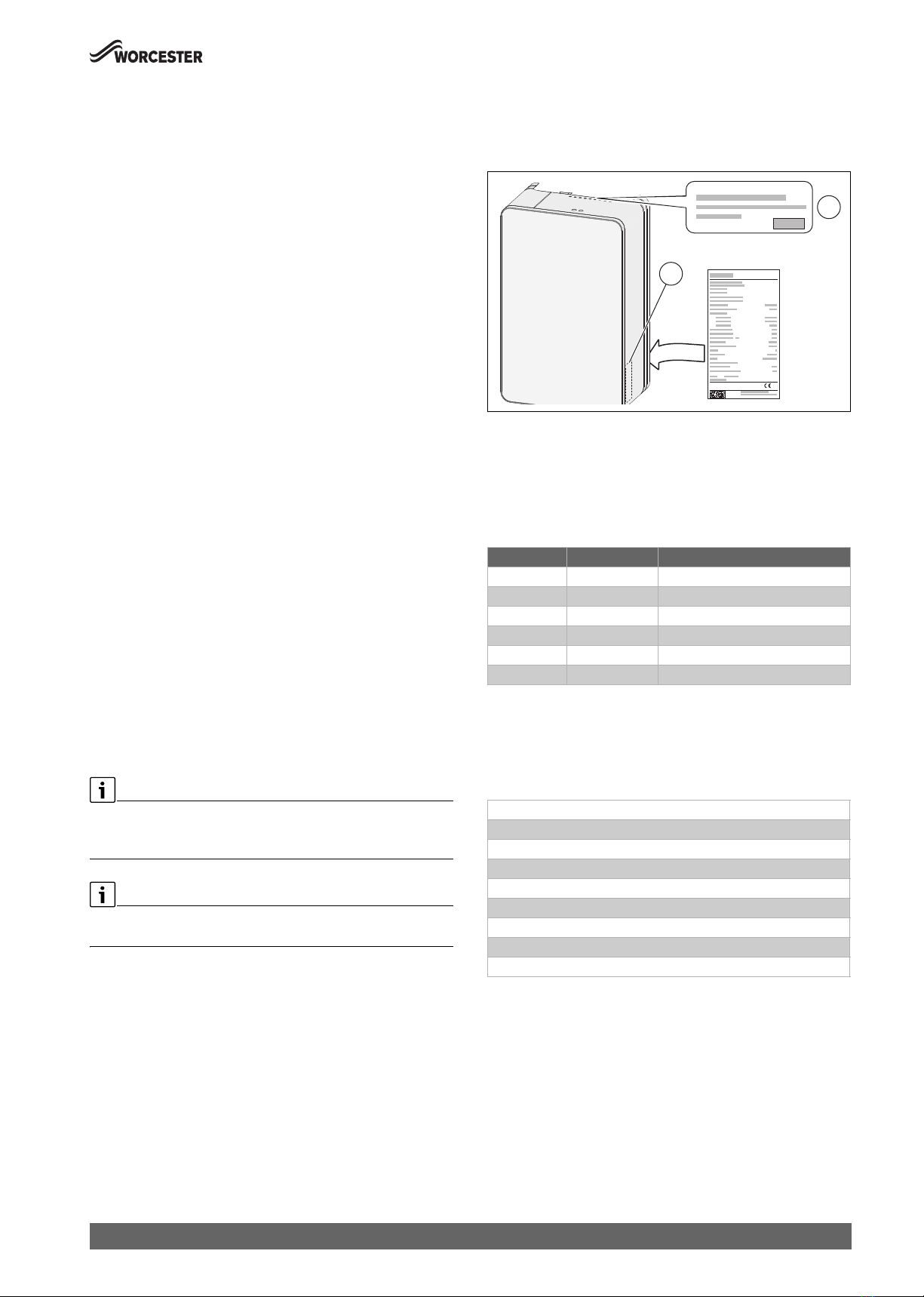
▶ To ensurecompliancewiththe intendeduse,observethe information
on the data plate and the specifications.
▶ Only install the HIU in frost-free room or enclosure. Ensure a ambient
temperature range of 2 °C to 30 °C.
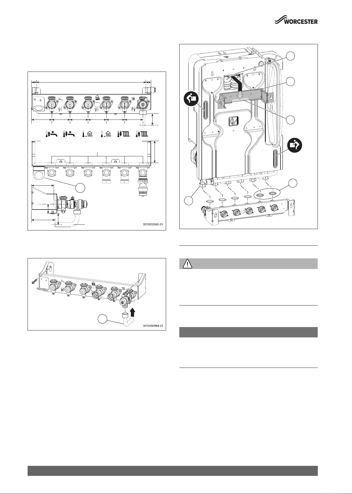
▶ Only install the HIU straight and vertically upright, as described in
these instructions.
HDanger of burns and scalds
Individual components and discharging water can be very hot and inflict
burns.
▶ Do not touch hot surfaces.
▶ Unless you know what the temperature of the discharging water is,
you should not touch it.
HInspection and maintenance
Regular inspection and maintenance are prerequisites for safe and
energy efficient operation of the heating system.
We recommend you inspect the HIU at least every three years in line with
BSRIA guidance.
▶ Have work carried out only by an approved installer.
▶ If any faults are discovered, have them remedied immediately.
HHandover to the user
When handing over the heating system, explain the operation and
operating conditions to the operator.
▶ Explain operation – with particular emphasis on all safety-related
actions.
▶ Highlight the following points in particular:
– Point out that modifications or repairs may be carried out only by
an competend contractor.
– To ensure safe and environmentally compatible operation, an
inspection every three years, and also cleaning and maintenance
if required, must be carried out.
▶ Point out the possible consequences (personal injury and possible
danger to life or material damage) of not carrying out inspection,
cleaning and maintenance correctly, or omitting it altogether.
Symbol Meaning
▶ a step in an action sequence
a reference to a related part in the document
• a list entry
–a list entry (second level)

Product Information
Greenstar – 6721852556 (2022/11)
4
▶ Hand over the installation and operating instructions to the user for
safekeeping.
2ProductInformation
2.1 Scope of delivery
▶ Check that the delivery is complete and undamaged.
Fig. 1 Scope of delivery of heat interface unit
[1] Heat Interface Unit
[2] Wall mounting bracket
[3] Installation and maintenance instructions, gaskets (10 x), drilling
template
2.2 Product description
The heat interface unit (HIU) is used to provide heating energy and
potable hot water in buildings supplied by district heating or central
heating systems.
The HIU complies with the COSHH regulations (Control of Substances
Hazardous to Health Regulations 1988).
To remove the cover of the wall mounted HIU:
▶ Undo the screws at the bottom [2] and lift cover [1] up and out of the
frame.
Fig. 2 Removing the cover of the wall mounted station
Fig. 3 Station with heating circuit with mixer
[1] DHW control valve
[2] Control unit
[3] Heating control valve
[4] Primary circuit air vent valve
[5] Heating circuit air vent valve
[6] Return temperature sensor NTC for heating circuit (primary side)
[7] Heating circuit plate heat exchanger (brazed stainless steel)
[8] Differential pressure control valve, do not change adjusting
screw! (optional)
[9] Flow temperature sensor NTC for heating circuit
[10] Heat meter (optional)
[11] Heating circulation pump
[12] Thermal bypass (optional)
[13] Heating circuit drain valve, flow
[14] Heating circuit drain valve, return
[15] Heating circuit pressure relief valve
[16] Heating circuit return connection 22 mm compression ring fitting
[17] Heating circuit flow connection 22 mm compression ring fitting
[18] Primary circuit return connection22 mm compression ring fitting
(option: flat face fitting)
[19] Primary circuit flow connection 22 mm compression ring fitting
(option: flat face fitting)
[20] Hot water connection (DHW) 22 mm compression ring fitting
[21] Cold water connection (CWC) 22 mm compression ring fitting
[22] Primary circuit drain valve and strainer
[23] Heat meter flow sensor connection M10x1
[24] Flow temperature sensor NTC primary circuit
[25] Flow turbine and limiter with strainer
[26] DHW pressure-relief valve
[27] DHW over temperature valve
[28] NTC temperature sensor DHW
[29] DHW plate heat exchanger (brazed stainless steel)
[30] Expansion Vessel
[31] DHW air vent valve
0010032940-001
1
2
3
6720808928-06.1Wo
1
2
00100 -0331735

Product Information
5
Greenstar – 6721852556 (2022/11)
System separation
• The two heat exchangers for DHW and heating hydraulically
disconnect the primary heating circuit from the heating circuit.
DHW mode
• Opening the water tap activates the flow turbine [31]. The minimum
volumetric flow rate is 2 l/min.
• The DHW control valve [1] modulates the heating water on the
primary side to achieve the preset DHW temperature.
• The control valve for the heating remains closed [3] (DHW priority
function).
• Primary side heating water flows through the plate heat exchanger
[32] and heats the potable water instantaneously.
• If there is a risk of scalding, the thermal overload protection [25]
interrupts the flow. The valve opens automatically following a cool
down time.
Heating mode
• The control valve for the DHW [1] remains closed until DHW is
requested (DHW priority function).
• The heating control valve [3] modulates according to the required
heating capacity. The flow temperature remains the same and
corresponds to the flow temperature of the primary circuit.
Summer bypass function
• This function bypasses the longer heating-up period of the pipework
in the primary circuit which occurs when the heat interface unit has
been inactive for a longer period. This reduces the DHW heating
waitingtimes.The heat exchangerisnotkeptwarmcontinuously.The
summer bypass function can be activated in two ways.
• Variant 1 (standard) - electronic keep hot without thermal bypass,
using the default electronic bypass. The DHW control valve [1] is
used to allow water to run through HIU. The trigger temperature for
this function is fixed at 41°C and can only be changed by a Sense II
room controller (accessory). With this version, the quantity of heat is
recorded by the heat meter (option) [10].
• Variant 2 (accessory) - using the thermal bypass option [12]: the
heating water in the primary circuit flows through the bypass valve.
This ensures that the temperature of the hot water at the heat
interface unit is 30-70 °C. In this case the quantity of heat is not
recorded by the heat meter (accessory) [12]!
If the bypass valve is installed, the electronic bypass function must not
be selected in the room controller and the jumper must be removed
(Fig. 53, page 29 [19]).
The BESA requirements are only achieved with the electronic bypass -
not with the thermal bypass (accessory).
Frost protection
• System frost protection: as soon as the temperature sensor [10]
sends a frost protection signal, the heating pump is activated.
• Device frost protection: as soon as the temperature at the flow
temperature sensor [24] for the heating is below 5 °C, the control
valve opens the heating.
Limiting the return temperature in the heating circuit
• If the system is designed correctly, it is not necessary to limit the
return temperature [8].
• The return temperature limit is set to 50 °C at the factory.
• This temperaturecan onlybe changed withthe roomcontroller Sense
II.
• When the room controller is removed, the set value is saved.
2.3 Type Plate
The data plate includes the performance information, approval data and
serialnumber ofthe product[2].Thereisan additionaldata platebehind
the control unit [1].
Fig. 4 Type plate and data plate
2.4 Appliance type overview and accessories
Example appliance: HIU KE
• HIU = heat interface unit
• E = differential pressure control valve (DPCV)
• K = higher DHW output
Table 2 Appliance type overview
Refer to the Technical product brochure for a complete overview of all
available accessories. Information on assembly is enclosed with the
accessories.
Table 3 Accessory part
2.5 Product dimensions and minimum clearances
The protection class of the station is IPX4D.
Typ Typ-Nr. Accessory NOT possible
HIU 7735600658 Heat meter wired Mbus
HIU1)
1) with heat meter wired Mbus (standard)
7735600726 Heat meter adapter kit
HIU E 7735600659 Heat meter wired Mbus
HIU E 1) 7735600724 Heat meter adapter kit
HIU KE 7735600661 Heat meter wired Mbus
HIU KE 1) 7735600725 Heat meter adapter kit
Flushing valve
Vertical connector pipes (set)
Heat meter adapter kit
Thermal overload protection
Sense II (room controller)
Security fixings
Keyless filling loop
Summer bypass valve
Mounting plate
2
0086
1
0010025537-01

Regulations
Greenstar – 6721852556 (2022/11)
6
Fig. 5 Dimensions, sizes in mm
Fig. 6 Minimum clearances in mm for assembly and maintenance
Assembly in a cabinet
The minimum clearances specified below apply in addition to the normal
minimum clearances.
▶ Make sure that the temperature in the cabinet does not exceed 35 °C.
▶ Provide ventilation openings at the top and bottom each of which are
at least 240 cm2.
Fig. 7
2.6 Declaration of conformity
The design and operating characteristics of this product comply with the
British requirements.
The UKCA marking declare that the product complies with all
the applicable British legislation, which is stipulated by
attaching these markings.
The complete text of the Declaration of Conformity is available on the
Internet: worcester-bosch.co.uk.
3Regulations
▶ Observe updated regulations or supplements. Theseregulations also
apply at the time of installation.
▶ Observe all standards and guidelines applicable to the installation
and operation of the system in your country and region.
Standards and Guidelines
•Building Regulations Part L (conservation of energy in buildings)
•BS12502 Part 1 and 2
•HSG85 (electrical separation)
•GS38 (test equipment)
•BS7671 (IET wiring regulations)
• CIBSE CP1(2020) Heat networks code of practice for the UK
• Local standards and regulations for the electrical connection and
safety equipment of the water-filled heating system.
263
440 270
127 50
390
18
19
79
48
65 65 65 65 65
18
700
582
37
81

Preparatory work
7
Greenstar – 6721852556 (2022/11)
4 Preparatory work
4.1 Observe general notices
▶ Remove the packaging, observing all notices in the packaging.
▶ Mount the HIU as close as possible to the most frequently used water
draw-off point.
▶ When assembling the pipework, secure the connections at the HIU to
prevent twisting.
Other components required
NOTICE
Push by due to excessively high differential pressure
The maximum differential pressure in the primary circuit of heat
interface units with integrated differential pressure control valve is
400 kPa (4000 mbar), and 80 kPa (800 mbar) without integrated
differential pressure control valve.
▶ Where necessary, install a suitable control to limit the differential
pressure.
▶ Protect the primary heating circuit with an expansion vessel and
pressure-relief valve in accordance with BS EN 12828.
As the heat interface unit is not always accessible, we recommend using
a central automatic air separator or a deaerator in the primary circuit.
▶ Install drain valves at all the low points in the system.
▶ Install air vents at all the highest points in the system.
▶ Install thermostatic radiator valves in accordance with CIBSE CP1.
DHW - water quality
▶ Comply with limits in the following table.
▶ Comply with UK Water Regulations.
CAUTION
Failure of the station due to calcification of heat exchanger.
▶ If the water hardness is 20°°dH or more, install a water softener unit.
To minimise calcification of the heat exchanger, we recommend you
install a water softener unit if the water hardness is 14°°dH or more.
Table 4 Suitability of the water supply
Heating water quality
Water treatment and quality for both the primary heat network and
tertiary heating circuit should comply with the water treatment guidance
contained within CIBSE CP1.Additionally, the below additives are
suitable for use with this product.
Table 5 Typical additives for the heating water
Floor heating
To protect the underfloor circuit in the event of faults:
▶ Mount thermal protection valve.
-or-
▶ Temperature switch on the flow pipe to the underfloor circuit
▶ Set the switching point of the temperature switch (minimum
temperature setpoint of underfloor heating circuit + 10 K).
4.2 Pipework installation
Any plastic pipe-work used on the central heating system must have a
polymeric oxygen barrier coating.
▶ Carry outa pipe networkcalculation todeterminethepipeworksizes.
Observe specified pressure losses of the HIU.
▶ Fit pipework and connections without stress.
▶ Sufficiently insulate all pipework leading to the HIU (according to
CIBSE CP1 guidance).
Showers/bidets
• Ensure that the shower is suitable for use with mains water pressure.
• If a shower head can be immersed in water or comes closer than
25mm from the top edge of a bath or shower tray spill over level then
an anti-siphon device must be fitted to the shower hose.
• Bidets with direct hot and cold mains water can be used (with the
approval of the local water authority) and must be the over rim
flushing type with shrouded outlets to prevent the fitting of hand held
sprays.
Water pressure
▶ Observe water pressure limits (specifications).
NOTICE
Risk of damage to household appliances!
Non-return, back flow prevention devices (including those associated
with water meters) fitted to the mains water supply can cause a pressure
build up which could damage the appliance and other household
appliances.
▶ Fit a mini expansion between the non-return valve, back flow
prevention device.
4.3 Installing the discharge pipe
CAUTION
Risk of scalding due to incorrectly installed discharge pipe!
▶ Mount discharge pipe so it cannot pose a danger when discharging
into a drain or tundish.
When the tundish is installed indoors it should have an odour trap. If the
temperatures in theprimarycircuitarehigherthan 85°C,werecommend
using a Hotun-Hiflun tundish.
▶ Install discharge pipe from the safety valve [1,3] in a pipe that is
suitable for the maximum operating temperature. Discharge into a
suitable drain or tundish internally. For external discharge, install as
set out in the figure.
▶ Install a partial elbow on the end to prevent freezing.
Unit Value
Water hardness °dH < 20
pH value 6.0 - 9.5
Conductivity S/cm 10 - 2790
Sulphate mg/l < 250
Chloride mg/l < 80
BASF Glythermin NF (20-62%) Sentinel X100 (1-2%)
Fernox F1 Sentinel X200
Fernox F1 express Sentinel X400
Fernox Alphi-11 Tyfocop Tyfocor L (25-80%)
Hoechst Antifrogen N (25-40%) MC1+ Protector
Hoechst Antifrogen N+L (40%) MC3+ Cleaner
Nalco Nalco (1-2%) MC2 Silencer
Nalco Varidos 1+1 (1-2%) MC ZERO (25-40%)
Nalco Varidos FSK (22-55%)

Assembly
Greenstar – 6721852556 (2022/11)
8
Fig. 8 Discharge pipe
[1] Discharge pipe (turned back onto external wall example)
[2] Outside wall
[3] Discharge pipe (into drain or gully example)
[4] External drain
4.4 Mounting the filling device
You have the following options for filling the system:
• Keyless filling loop (accessory, see separate instructions)
• Filling loop provided by the customer on the cold mains inlet
• Filling loop provided by the customer on the primary side return
System separator provided by the customer
▶ The sealed heating system must be filled using a WRAS approved
filling loop. See the following figure.
▶ Make sure the heating system is treated using a suitable inhibitor (
Appendix, Specifications).
▶ Mount filling loop between the pipes of the primary side return or
cold water inlet and the heating flow.
Fig. 9 Filling loop provided by the customer
[1] Primary circuit return / cold mains inlet
[2] Shut-off valve
[3] Non-return component
[4] Test point
[5] Pipework (filling loop)
[6] Heating circuit flow
5 Assembly
5.1 Quick reference guide
▶ For detailed information, refer to the following chapters.
Fig. 10 Attach template, drill holes, install wall mounting bracket and
mounting plate
Fig. 11 Insert gaskets and hang HIU
1
2
3
4
2
3
4
1
2
6720818077-38.1Wo
0010035460-01
0010034532-01

Assembly
9
Greenstar – 6721852556 (2022/11)
Fig. 12 Electric connection
Fig. 13 Vent: HIU and radiator
Fig. 14 Set rotary selector on control unit
Fig. 15 Set room controller, if installed
5.2 Mounting wall mounting bracket
NOTICE
Incorrect assembly can cause material damage.
If the device is assembled incorrectly, it may fall off the wall.
▶ Only install the device on a rigid, solid wall. This wall must be able to
carry the weight of the device and must at least be as large as the
bearing surface of the device.
▶ Only use screws and rawl plugs that are suitable for the wall type and
weight of the device.
The following hole patterns are printed on both sides of the drilling
template:
• Installation on finished wall, wall mounting bracket at top, mounting
plate at bottom.
• Installation on unfinished wall, hole at top for hanging the HIU when
installing cabinet provided by the customer on unfinished wall,
mounting plate at bottom.
▶ Align template with spirit level [1]and attach towall [2]. Observe the
minimum clearances.
▶ Drill holes for wall mounting bracket [3] and mounting plate
(accessory).
Fig. 16 Drilling template (wall mounting bracket at top), on finished
walls
▶ Attach wall mounting bracket [1] securely to wall. Use appropriate
screws [2] and anchors for this.
Fig. 17 Installing the wall mounting bracket
0010023106-010010023106-01
230V
3.
0010025527-010010025527-01
6.
3
2
2
1
0010017769-010010017769-01
2
1

Electrical connection
Greenstar – 6721852556 (2022/11)
10
5.3 Installing the mounting plate (accessory)
The mounting plate makes it easier to connect the pipework to the HIU
and is a necessary accessory.
▶ Attach mounting plate securely.
▶ Connect pipework to mounting plate.
Fig. 18 Mounting plate, dimensions in mm
[1] Optional position for pressure gauge
▶ Mount connection elbow [1] on heating return connection.
Fig. 19 Mounting connection elbow
5.4 Hanging the HIU
▶ Insert the enclosed gaskets before hanging the HIU. The blue gaskets
[4] are for the potable water connections.
▶ Place the suspension point of the HIU [1] on the hook [3] of the wall
mounting bracket [2].
▶ Tighten the connections [5].
Fig. 20 Place the HIU on the wall mounting bracket
6 Electrical connection
WARNING
Danger to life from electric shock!
Touching live electrical parts can cause an electric shock.
▶ Before installing accessories: Disconnect the power supply to the
heat generator, building management system and any other BUS
systems (all poles) and secure against unintentional reconnection.
You canalso findinformationonsafeelectrical isolationin the Health and
Safety Executive guidance HSG85 and in the GS38.
NOTICE
Overload damage
Never exceed the specified maximum power input (specifications).
▶ Install a standard all-pole isolator (to EN60335-1) to disconnect the
mains voltage.
Electrical work may only be performed by electricians.
▶ Only connect to a single phase and earth system.
▶ Any system/appliances connected to the HIU must not have a
separate power supply.
▶ Use a Type A residual current device if additional protection is
required.
The module is prewired. All you need to do is connect the accessories (if
applicable) and connect to the mains power supply.
390
6572
83
65 65 65
78
78
33
65 40
40
19
18
Ø22mm
Ø15mm
18
1
1
0010032964-02
3
1
2
5
4

Electrical connection
11
Greenstar – 6721852556 (2022/11)
6.1 Opening the control unit
To access the unit:
▶ Pull the unit [1] forwards and attach to the holder of the heat
exchanger [2].
Fig. 21 Move the unit into the service position
▶ Release locking devices [4].
▶ Fold up cover [3].
Fig. 22 Fold up cover
6.2 Control unit terminals
In this chapter, you will find an overview of the components that are
connected at the factory and the components you need to connect
yourself (chapter: specifications, wiring diagram).
The following chapters show how to establish the connection itself and
secure the cable.
Connections made to the control unit at the factory
Table 6 Components connected to the control unit at the factory
Accessory connections to be established on site (if available)
Table 7 Accessory connections to 230 V mains voltage, if available
Table 8 Accessory connections to low voltage (signal cable), if available
6.3 Examples: wiring the control unit
Thetwo examplesbelow show whichconnectionsyoucanuse toconnect
accessories to the control unit.
Connection Function Cables/wires
Heating pump (only
with HIU with
integrated pump)
• Phase (63, brown)
• PEN conductor (N,
blue)
• Earthing (green/
yellow)
Turbine, DHW flow rate •Red(4)
• Yellow (2)
• Black (1)
NTC temperature
sensor, primary circuit
• White (2)
• White (1)
NTC temperature
sensor DHW
• Blue (2)
• Blue (1)
Heating control valve • Brown (4)
• Black (3)
• White (2)
• Yellow (1)
1
2
0010017775-010010017775-01
0010017849-010010017849-01
3
4
DHW control valve • Blue (4)
• Green (3)
• Grey (2)
• Red (1)
Flow temperature
sensor NTC, heating
circuit
• Yellow (2)
• Yellow (1)
Return temperature
sensor NTC, heating
circuit
• Green (2)
• Green (1)
Electronic summer
bypass
•Jumper
Connection Function Cables/wires
Temperature limiter,
underfloor heating
system
•Voltfree
External control
modules 230 V
(output)
• Phase (L)
• PEN conductor (N)
•Earthing
Mains power supply to
HIU (input)
• Phase (L)
• PEN conductor (N)
•Earthing
External time and
temperature control
(e.g. 230 V room
thermostat)
• On-off switch (LR)
• Phase (L)
• PEN conductor (N)
•Earthing
Connection Function Cables/wires
BUSconnection,Sense
II room temperature-
dependent controller
• Not polarity sensitive
Outdoor ambient
temperature sensor
• Not polarity sensitive
Connection Function Cables/wires
LR LN

Electrical connection
Greenstar – 6721852556 (2022/11)
12
Heating circuit with radiator
Fig. 23 Example - heating with radiators
Table 9 Option 1: Sense II room controller connection
Table 10 Option 2: 230 V programmable room thermostat
Heating circuit without mixer with underfloor heating system
Fig. 24 Example - underfloor heating system
Table 11 Option 1: Sense II room controller connection
Table 12 Option 2: 230 V programmable room thermostat
6.4 Cable preparations
WARNING
Risk of fire due to damaged cables!
Hot appliance parts in the HIU can damage the cables and cause fire.
▶ Do not route cables along hot appliance components.
NOTICE
Damage to control unit!
Small pieces of wire can cause shorts and damage to electronics.
▶ Make sure when stripping the cables that copper strands do not fall
into the module.
▶ Strip the cable so that the earth conductor is longer than the other
wires.
Fig. 25 Cable preparations (here: power cable)
6.5 Connecting and securing the cable
Each cable entering the control unit must pass through and be secured
by a cable clamp.
Connection Function
Outdoor ambient temperature sensor
BUS connection for Sense II room temperature-
dependent controller
Connection Function
External time and temperature control (e.g.
230 V room thermostat)
6720808928-39.1Wo
LR LN
6720808928-40.1Wo
T
Connection Function
Outdoor ambient temperature sensor
BUS connection for Sense II room temperature-
dependent controller
Temperature switch, underfloor heating system
Connection Function
Temperature switch, underfloor heating system
External time and temperature control (e.g.
230 V room thermostat)
LR LN
0010017852-010010017852-01
36-40mm
26-30mm
6-8mm 6-8mm
N
L

Commissioning
13
Greenstar – 6721852556 (2022/11)
To remove the cover [1]:
▶ Release locking devices [2] with a screwdriver.
Fig. 26 Remove cover
▶ Undo locking screw [3].
▶ Feed the cable [4] through the cable clamp. Make sure that the cable
is long enough to reach the connections.
▶ Fix cable with locking screw [3].
▶ Connect the cable to the terminals.
Fig. 27 Securing the cables
7 Commissioning
Make all electrical connections in accordance with the wiring diagram
and then carry out the commissioning!
▶ Observe the installation instructions for all components and
assemblies in the system.
CAUTION
Risk of damage to system through pump failure!
▶ Fill and vent the system before switching it on so that the pumps do
not run dry.
Procedure:
To commission the overall system, follow the sequence of steps below
(described in the following chapters):
1. Fill flush and vent the system.
2. Adjust the control unit at the rotary selector
3. Adjust the heating circuit pump (if required).
4. Adjust the room control for the heat interface unit and the heating
circuit (if room control is installed).
5. Fill out the commissioning checklist.
7.1 Filling, flushing and venting the system
Purging the primary circuit
▶ Refer to CIBSE CP1 for water quality requirements and to BSRIA
BG29 for system flushing.
The primary circuit can be flushed without heat interface unit using the
flushing kit which is available as an accessory.
▶ Close the shut-off valves on the primary side.
▶ Open the shut-off valve on the flushing kit to flush the pipework.
▶ Close the isolation valve once flushing is complete.
Fig. 28 Flushing kit shut-off valve (accessory)
Heat Interface Unit
CAUTION
Failure of the flow turbine
▶ Open several DHW draw-off points to prevent the formation of
compressed air pockets in the pipework.
▶ Carefully fill the system: slowly open the shut-off devices.
▶ To avoid water hammer: slowly open the shut-off valves at the cold
water inlet and hot water outlet.
▶ Flush the system correctly.
0010017851-010010017851-01
1
222
0010017854-010010017854-01
4
3
4
3
230V
0-30V
6720808928-38.1Wo
90°
90°

Commissioning
Greenstar – 6721852556 (2022/11)
14
▶ Clean strainer (chapter "Inspection and maintenance").
▶ Fill the system and check for tightness.
▶ Close the shut-off valves once the pressure gauge has reached
between 1 and 1.5 bar.
▶ Switch on the power supply.
▶ Ensure the correct primary flow rates are available to the HIU (
chapter Heat meter (Option)).
Control valves: the valves can be fully opened via the service function
. The valve is calibrated first and then after 10 seconds the valve is
openedfor10 minutes.Whenthe powersupplyis interrupted, thevalves
remain in position.
When the air vent valves are opened, water may be discharged from the
valves.
▶ Collect discharging water with a vessel or cloth.
To vent the DHW circuit:
▶ Open the water tap. Open the air vent valve on the DHW heat
exchanger to allow air to escape.
To vent the secondary circuit (heating circuit):
▶ Open the thermostatic valves to open the control valve.
▶ Vent the radiators.
To vent the heating circuit:
If the heat meter is reading Error Code E7 the venting process needs to
be repeated (page 16).
▶ Open both control valveswith the service function . Open the air
ventvalveonthe heatingcircuitheat exchangertoallowair to escape.
▶ Make sure that the air vents are fully closed after venting.
Fig. 29 Manual vent points
Overall system
Air bound in the water is only released after a specific time as a result of
pressure fluctuations as well as solution and degassing processes.
▶ After 1-2 weeks, vent the system again and top up if required.
▶ Vent at every highest point in the system.
7.2 Adjusting the control unit
The LED On/Off indicators of the module are visible through the
enclosure.
Fig. 30 LED On/Off indicators, rotary selectors on the control unit
If different values are set at the control unit and the room controller (e.g.
Sense II), the lower value is used for control.
To set the required set DHW temperature, observe the DHW output.
CIBSE CP1 recommends for the DHW temperature to be set at 50. (
Specifications).
control unit LED display
▶ Set the required values at both rotary selectors.
Table 13 LED displays and positions on rotary selectors
Calibration of the control valves is not required during commissioning -
only when a control valve fault is displayed (chapter "Faults").
Description
LED red Fault chapter
LED yellow Rotary selector at 00
Rotary selector at 30 - 70: Fault chapter
LED green Normal mode with set value (30 - 70)
LED flashes red Invalid position (bypass, DHW and circulation pump
function, heating function deactivated)
LED flashes
yellow
Heat interface unit starts
LED flashes
green
Calibration or Service mode ( / )
Calibration and test mode of the control valve (once
10 seconds have elapsed, the valve is opened for 10
minutes).
Service mode of DHW circulation pump
Heating circuit without mixer.
For the heating circuit without mixer the rotary
selector must be at this position!
00 Function off
30- 60(35 - 70) Setting the temperature

Commissioning
15
Greenstar – 6721852556 (2022/11)
7.3 Control valve status indicators
To be able to see the On/Off indicators of the control valves:
▶ Remove the enclosure, insulation and control unit.
LED power-saving mode: if the position of the valves does not change for
15 seconds, the LED displays are not visible.
Table 14 Control valve status indicators
Fig. 31 Circle = green, square = blue, triangle = orange
7.4 Setting the heating pump
The heating circulation pump has five LED indicators.
Fig. 32 Status displays of the integrated heating circulation pump
[1] Yellow LED
[2] Green LED
[3] Selection button
Available hydraulic pressure
Default pump curve setting: PP3 (highest proportional pressure curve).
Fig. 33 Available hydraulic pressure
[1] PP1: lowest proportional pressure curve
[2] PP2: intermediate proportional pressure curve
[3] PP3: highest proportional pressure curve
The head (pressure) falls as the heating load reduces and rises as the
heating load increases.
Settings
Momentary presses of the selection button will cycle through the
available pump curves. After 10 seconds of inactivity the selected
setting will be activated.
▶ To change the setting press and hold the selection button for 2
seconds to enter setting mode.
Fig. 34 Pump curve adjustment
[1] Proportional pressure curve auto adapt
[2] Constant pressure auto
[3] Proportional pressure curve PP1
[4] Proportional pressure curve PP2
[5] Proportional pressure curve PP3 max
[6] Constant pressure curve PP1
[7] Constant pressure curve PP2
[8] Constant pressure curve PP3 max
[9] Constant curve CC1
[10] Constant curve CC2
[11] Constant curve CC3 max
Indicators Description
Orange, blue, green Valve in start up mode. Calibration in progress.
Green Valve is completely open.
Green and blue Valve is open between 60 and 99,9 %.
Blue Valve is open between 40 and 60 %.
Blue and orange Valve is open between 0.1 and 40 %.
Orange Valve is completely closed.
0010017858-010010017858-01
[l/h]
0
50
100
150
200
V
250
300
350
400
p
[mbar]
0
60
120
180
240
300
360
420
480
540
600
660
720
780
840
900
960
1020
1080
1140
1200
1260
1320
1380
1440
1500
1
2
3
6720808926-55.1Wo
123 4 5 6 7 8 9 10 11

Commissioning
Greenstar – 6721852556 (2022/11)
16
7.5 Heat meter (Option)
The energy meter uses an ultrasonic flow sensor to record all billing-
relevant data for measuring the energy consumed by heating and hot
water. The data read out is displayed on different loops in the display.
The seal on the energymeter must not be damaged! A damaged seal will
result in immediate invalidation of the factory warranty and verification.
Thecablessupplied withthe meter must neitherbe shortened,extended
nor changed in any other way.
Legal regulations and operating instructions for the use of energy meters
must be observed! The installation must only be carried out by a
specialist energy meter installation and electrical company. The
personnel must be trained in the installation and handling of energy
meters and electrical devices as well as the applicable guidelines.
Medium: Water, according to CEN/TR 16911. If water additives are used
(e.g. corrosion protection), the user must make sure that the corrosion
resistance is adequate.
If the flow sensor is insulated with the pipeline, the calculator must be
accessible.
Sensor
The connecting cables must not be shortened or extended!
Communication general
Communication modules must be secured so that opening of meters is
only possible by destroying the securing points (e.g. with locking
varnish).
Communication via radio
The integrated radio function is for communication via 868 MHz or 434
MHz OMS/M-Bus (Open Metering System) and has the following
specifications:
• The module transmits every 8 ... 256 s (send period max. 0.1 % of
duty cycle (min. 8s); variable, depending on protocol length and
programming).
• The communication always transfers the currently measured data.
• Transmission frequencies: 434 MHz, transmission power (EN 300
220-2 V3.2.1): 10mW e.r.p. 868 MHz, transmission power (EN 300
220-2 V3.2.1): 25mW e.r.p.
• Encrypted protocol: Real Data Radio or Open Metering Standard.
• Reading modes: Walk-By, Drive-By, Fixed-Network
• For problematic radio installations (shielding) the external wireless
module set can also be used.
M-Bus Communication module
The wired M-Bus communication module is a serial interface for
communication with external M-Bus monitoring devices and billing
systems supporting connection via the M-Bus standard.
• The connection is not polarity-sensitive and is electrically isolated. M-
Bus protocol standardised according to EN 1434;
• 300 or 2400 baud (auto baud detect).
• Connection for 2 x 2.5 mm².Power consumption: One M-Bus load
▶ Connect the heat meter M-Bus cable and cable used to connect to the
M-Buscompatible external equipment into theconnectorblock[1]in
the control unit.
Fig. 35 M-Bus connection
Operation
Pressing the button awakens the meter from power saving mode and
activates the display.
• Short button press (< 3 seconds): shift within one loop.
• Long button press (> 3 seconds): switches to the next loop.
• If the button is not pressed for more than 4 minutes, the controller
switches off and switches to power save mode.
Display
Fig. 36 Display
[1] Quadrant display
[2] Loop number
[3] Tariff loop
[4] Fault symbol
[5] Calibrated value
[6] Maximum value
[7] Button
Menu structure - display sequences
The energy meter has 5 different display sequences (loops). The loops
are labelled 1 to 5 in the display.
Table 15 Loop 1- main loop
Window 1
1.1 Accumulated energy
1.2 Volume
1.3 Accumulated cooling energy (only for cooling tariff)
1.4 Flow
1.5 Power
1.6 Flow/return flow temperature
1.7 Differential temperature
1.8 Operating days
1.9 Error status
1.10 Display test
1
563214
MBtm
x100
GPM GJgal
max
V
-V
7
00100 8-014510

Commissioning
17
Greenstar – 6721852556 (2022/11)
Table 16 Loop 2 - Effective date
Table 17 Loop 3- Information loop
Table 18 Loop 4- Pulse loop
Table 19 Loop 6- Month loop
7.6 Commissioning checklist
▶ Complete and sign checklist following assembly and commissioning.
Table 20 General information on the system
Window 1 Window 2 Window 3
2.1 Accounting date 1
Date
Accounting date 1
Energy kWh
Accd 1 A
2.2 Accd. 1 Date of future accounting date 1
2.3 Accounting date 1
previous year date
Accounting date 1
previous year energy
Accd 1L
2.4 Accounting date 2
date
Accounting date 2
energy
Accd 2A
2.5 Accd 2 Future accounting date
2.6 Accounting date 2
previous year date
Accounting date 2
previous year energy
Accd 2L
2.7 Accounting date 1 Pulse input 1 Volume pulse input
1
Window 1 Window 2
3.1 Current date Current time
3.2 Sec_Adr Secondary address
3.3 Pri_Adr 1 Primary address 1
3.4 Pri_Adr 2 Primary address 2
3.5 Installation position (cold pipe/
return pipe as standard)
(depending on the setting)
3.6 Port 1 0 (no. of installed module in
port 1)
3.7 Port 2 1 (no. of installed module in
port 2)
3.8 Status of the integrated radio
3.9 Software version Check sum
Window 1 Window 2 Window3
4.1 Pulse input 1 Cumulative value
pulse input 1
Value of pulse (L/P)
4.2 Pulse input 2 Cumulative value
pulse input 2
Value of pulse (L/P)
4.3 Pulse output 1 Value of pulse (L/P)
4.4 Pulse output 2 Value of pulse (L/P)
Window 1 Window 2 Window 3 Window 4
6.1 “LOG” Date-1 Energy Max. flow rate
6.2 “LOG” Date-2 Energy Max. flow rate
....
6.24 “LOG” Date-24 Energy Max. flow rate
User:
System location:
Installer:
Heat interface unit type:
Commissioning checklist
Mains power supply compliant with standards?
1. System hydraulics / primary circuit
Heating flushed, filled and checked for leaks?
Vented the system?
Differential pressure and volumetric flow rate of the central
primary pump checked?
If fitted, has the flushing valve been closed?
q
Operating pressure in primary circuit measured?
_____ bar
Central pressure-relief valve installed?
Strainer checked and cleaned?
2. Heating / tertiary circuit
Heating system flushed, cleaned and vented?
Has power been left switched on to ensure the pump anti
seize function can operate?
Have radiator flow rates been balanced?
Heating circuit with mixer: position of rotary selector?
_________
Underfloor heating system: overheating protection
installed?
Setting of heating circuit pump checked?
Does lowering the room thermostat remove the demand for
HTG?
Heating flow temperature (at HIU) measured?
______ °C
Heating return temperature (at HIU) measured?
______ °C
Have TRV's been mounted horizontally on radiators? q
Record the return temperature limiter set point (default 50)
if adjusted? ______ °C
Primary circuit flow temperature measured?
______ °C

Shutdown
Greenstar – 6721852556 (2022/11)
18
Table 21 Commissioning checklist
Table 22
8Shutdown
NOTICE
Damage due to freezing!
▶ Leave the heating system switched on if there is a risk of frost.
If the heating system is decommissioned for a longer period:
▶ Interrupt the power supply to the HIU.
▶ When there is a risk of frost and the HIU is decommissioned,
completely drain it on the heating and on the potable water side.
9Environment/disposal
Environmental protection is a fundamental corporate strategy of the
Bosch Group.
The quality of our products, their economy and environmental safety are
all of equal importance to us and all environmental protection legislation
and regulations are strictly observed.
We use the best possible technology and materials for protecting the
environment taking account of economic considerations.
Packaging
Where packaging is concerned, we participate in country-specific
recycling processes that ensure optimum recycling.
Allof our packagingmaterialsareenvironmentallycompatibleandcanbe
recycled.
Used appliances
Used appliances contain valuable materials that can be recycled.
Thevarious assembliescan beeasily dismantled. Syntheticmaterialsare
marked accordingly. Assemblies cantherefore be sorted by composition
and passed on for recycling or disposal.
Old electrical and electronic appliances
This symbol means that the product must not be disposed
of with other waste, and instead must be taken to the waste
collection points for treatment, collection, recycling and
disposal.
The symbol is valid in countries where waste electrical and
electronic equipment regulations apply, e.g. "(UK) Waste Electrical and
Electronic Equipment Regulations 2013 (as amended)". These
regulations define the framework for the return and recycling of old
electronic appliances that apply in each country.
As electronic devices may contain hazardous substances, it needs to be
recycled responsibly in order to minimize any potential harm to the
environment and human health. Furthermore, recycling of electronic
scrap helps preserve natural resources.
For additional information on the environmentally compatible disposal
of old electrical and electronic appliances, please contact the relevant
local authorities, your household waste disposal service or the retailer
where you purchased the product.
You can find more information here:
www.weee.bosch-thermotechnology.com/
Primary circuit average return temperature measured?
______ °C
Is the average return temperate 40 degrees or below?
______ °C
Volumetric flow rate of primary circuit?
▶ Record the average primary flow rate over a two minute
period, during a DHW demand at the kitchen sink.
____ l/min
3. DHW
Bypass valve installed? Yes/No
_________
Bypass valve setting?
_________
DHW circulation pump setting?
_________
Position of DHW rotary selector?
_________
Cold water temperature at inlet measured?
______ °C
DHW temperature at outlet measured?
______ °C
DHW volumetric flow rate measured?
▶ Make sure that the required volumetric flow rate and
temperature increase is achieved for each outlet.
____ l/min
Primary circuit average return temperature measured?
______ °C
Volumetric flow rate of primary circuit?
____ l/min
Signature of operator:
Signature of installer:
Other:
Date:
Commissioning checklist

Inspection and service
19
Greenstar – 6721852556 (2022/11)
10 Inspection and service
WARNING
Risk to life from electric shock!
Touching live electrical parts can cause an electric shock.
▶ Before working on electrical parts, disconnect all phases of the
power supply (fuse/circuit breaker) and lock the isolator switch to
prevent unintentional reconnection.
10.1 Inspection and maintenance report
To safeguard the functional reliability of the system and the validity of
guarantee claims:
▶ Check the system every 3 years (inspection). Immediately remedy all
faults (maintenance).
▶ Observe instructions for the components!
▶ Perform the tasks listed below.
▶ Use the table as a template for further documentation.
Table 23 General information on the system
Table 24 Inspection and maintenance work
User: System location:
Heat interface unit type: Room controller (if installed):
Inspection and maintenance work Inspection/maintenance
1. 2. 3. 4. 5. 6.
Date:
Average return temperature on primary side
__________ °C __________ °C __________ °C __________ °C __________ °C __________ °C
Secondary heating T
__________ °C __________ °C __________ °C __________ °C __________ °C __________ °C
Flow temperature on primary side with DHW draw-off
__________ °C __________ °C __________ °C __________ °C __________ °C __________ °C
Return temperature on primary side with DHW draw-
off __________ °C __________ °C __________ °C __________ °C __________ °C __________ °C
Primary circuit: volumetric flow rate with DHW draw-
off (measure or read off at heat meter) _________l/h _________l/h _________l/h _________l/h _________l/h _________l/h
Potable Hot Water outlet temperature
__________ °C __________ °C __________ °C __________ °C __________ °C __________ °C
Potable hot water flow rate
_________l/min _________l/min _________l/min _________l/min _________l/min _________l/min
Filter checked/cleaned?
Visual inspection and function check carried out?
Setting/time at DHW circulation pump checked (if
installed)?
Comments:
Company stamp / date / signature

Inspection and service
Greenstar – 6721852556 (2022/11)
20
10.2 Cleaning the primary strainer
Draining the appliance
To drain the primary circuit and the heating system:
▶ Disconnect heat interface unit with shut-off valves from the primary
circuit and the heating system.
▶ Connect hose [3] to the drain valve.
To drain the heat interface unit:
▶ Open the air vents at the top of the desired circuit.
▶ Close the air vents again after draining!
▶ Turn the drain valve [1] anti-clockwise to open [2].
Fig. 37 Drain point connection
Remove the strainer in the primary circuit
▶ Remove the drainage assembly from the connection [2].
▶ Replace the gasket [3] if required.
▶ Clean the strainer [1].
Fig. 38 Remove and clean the strainer
10.3 Replacing components
Draining the appliance
To drain the primary circuit and the heating system:
▶ Disconnect heat interface unit with shut-off valves from the primary
circuit and the heating system.
▶ Connect hose [3] to the drain valve.
To drain the heat interface unit:
▶ Open the air vents at the top of the desired circuit.
▶ Close the air vents again after draining!
▶ Turn the drain valve [1] anti-clockwise to open [2].
Fig. 39 Drain point connection
To drain the domestic water system:
▶ Isolate the cold mains inlet isolation valve.
▶ Drain the domestic water system.
Heat exchanger
NOTICE
Material damage and leaks due to incorrect installation!
If the retention bracket is loosened or tightened unevenly this could
cause damage and leaks.
▶ Loosen or tighten the screws on the retention brackets evenly.
▶ Drain the HIU completely.
▶ Loosen the screws on the retention brackets [2] evenly.
▶ Pull the retention brackets off the heat exchanger [1].
▶ Replace the gaskets [3] of the connecting plates [4, 5] if required.
▶ Installthe newheat exchanger so thearrowpoints towards the centre
of the appliance.
▶ Purge the system correctly and check for leaks.
▶ Vent water circuits sufficiently (follow the procedure set out in the
commissioning instructions).
Fig. 40 Removing the heat exchanger
Control valves
▶ Drain the HIU completely.
6720808926-35.1Wo
1
3
2
2
2
3
1
0010018673-010010018673-01
6720808926-35.1Wo
1
3
2
0010032049-010010032049-01
4
5
1
2
3
This manual suits for next models
9
Table of contents
Other Worcester Controllers manuals
Popular Controllers manuals by other brands

Duncanco
Duncanco AV Series Installation & maintenance manual

LS Industrial Systems
LS Industrial Systems XBF-HO02A user manual

EAS Electric
EAS Electric ECRL10B instruction manual

Electric Time
Electric Time TBX user manual

Autonics
Autonics PMC-2HSP Series product manual

Plum
Plum ecoMAX860P1-K STANDARD Installation and operating manual