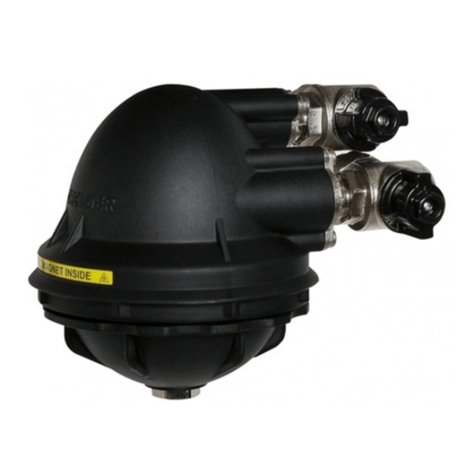
Worcester Greenstar 80mm Flexi RF Flue User manual

6721814542 2019/09 UK/IE
Flue kit installation instructions
Floor standing gas-fired condensing appliance flue
Greenstar 80mm Flexi RF Flue
0010029118-001
Flexible Flue Liner

Table of contents
Greenstar 80mm Flexi RF Flue – 6721814542 2019/09
2
Table of contents 1 Explanation of symbols and safety instructions
1.1 Explanation of symbols
Warnings
In warnings, signal words at the beginning of a warning are used to
indicate the type and seriousness of the ensuing risk if measures for
minimising danger are not taken.
The following signal words are defined and can be used in this document:
DANGER:
DANGER indicates that severe or life-threatening personal injury will
occur.
WARNING:
WARNING indicates that severe to life-threatening personal injury may
occur.
CAUTION:
CAUTION indicates that minor to medium personal injury may occur.
NOTICE:
NOTICE indicates that material damage may occur.
Important information
The info symbol indicates important information where there is no risk to
people or property.
Additional symbols
Table 1
1.2 General safety instructions
HImportant - These instructions are to be used in
conjunction with appliance Installation and
maintenance instructions.
Please read these instructions in conjunction with the
appliance Installation and maintenance instructions
manual carefully before starting installation.
▶ Observe all the safety precautions described in the
Installation and maintenance instructions for the
appliance this accessory is being installed onto.
HDanger to life from poisoning by flue gas
There is a danger to life from escaping flue gas.
▶ Ensure that flues and gaskets are not damaged.
1 Explanation of symbols and safety instructions . . . . . . . . . . . 2
1.1 Explanation of symbols . . . . . . . . . . . . . . . . . . . . . . . . . . 2
1.2 General safety instructions . . . . . . . . . . . . . . . . . . . . . . . 2
1.3 Requirements . . . . . . . . . . . . . . . . . . . . . . . . . . . . . . . . . . 3
2 Product information . . . . . . . . . . . . . . . . . . . . . . . . . . . . . . . . . . 4
2.1 RS Flexible flue components (80mmØ ). . . . . . . . . . . . . 4
2.2 Flue extension components. . . . . . . . . . . . . . . . . . . . . . . 5
3 Pre-Installation. . . . . . . . . . . . . . . . . . . . . . . . . . . . . . . . . . . . . . . 5
3.1 Chimney requirements. . . . . . . . . . . . . . . . . . . . . . . . . . . 5
3.2 Chimney preparation . . . . . . . . . . . . . . . . . . . . . . . . . . . . 6
3.3 Calculating the effective flue length . . . . . . . . . . . . . . . . 6
4 Installation . . . . . . . . . . . . . . . . . . . . . . . . . . . . . . . . . . . . . . . . . . 7
4.1 Creating the chimney opening. . . . . . . . . . . . . . . . . . . . . 7
4.2 Installing the flue elbow support . . . . . . . . . . . . . . . . . . . 8
4.3 Assembling the flexible flue. . . . . . . . . . . . . . . . . . . . . . . 8
4.4 Flexible flue liner installation. . . . . . . . . . . . . . . . . . . . . 10
4.5 Installing flue terminal and cowl . . . . . . . . . . . . . . . . . .11
4.6 Converting the flue outlet . . . . . . . . . . . . . . . . . . . . . . . 12
4.7 Fitting the flue adaptor. . . . . . . . . . . . . . . . . . . . . . . . . . 12
4.8 Extensions and elbows. . . . . . . . . . . . . . . . . . . . . . . . . . 13
4.9 Fitting the horizontal flue. . . . . . . . . . . . . . . . . . . . . . . . 14
5 Servicing and spares . . . . . . . . . . . . . . . . . . . . . . . . . . . . . . . . . 15
5.1 Servicing. . . . . . . . . . . . . . . . . . . . . . . . . . . . . . . . . . . . . 15
5.2 Spares. . . . . . . . . . . . . . . . . . . . . . . . . . . . . . . . . . . . . . . 15
Symbol Meaning
▶ a step in an action sequence
a reference to a related part in the document
• a list entry
– a list entry (second level)

Explanation of symbols and safety instructions
3
Greenstar 80mm Flexi RF Flue – 6721814542 2019/09
HDanger of death from poisoning by flue gas due
to inadequate combustion
Danger of death due to flue gas leak. If flues are
damaged or leaking, or if you smell flue gas, observe
the following rules.
▶ Close the fuel in-feed.
▶ Open doors and windows.
▶ If necessary, warn all residents and leave the
building.
▶ Prevent third parties from entering the building.
▶ Rectify any damage to the flue gas pipe
immediately.
▶ Check the combustion air supply.
▶ Do not cover or reduce the size of ventilation
openings in doors, windows and walls.
▶ Ensure that there is adequate combustion air
supply, including for any appliances installed at a
later date, e.g. extractor fans, kitchen fans or air
conditioning units that discharge air to the outside.
▶ Never operate the device if there is insufficient
combustion air supply.
HElectrical work
Electrical work must only be carried out by electrical
installation contractors.
Before starting electrical work:
▶ Isolate all poles of the mains voltage and secure
against re-connection.
▶ Make sure the mains voltage is disconnected.
▶ Observe the wiring diagrams of other system
components as well.
HPackaging
The following points should be observed during
unpacking.
▶ Check the delivery immediately upon receipt for
completeness and possible transport damage.
▶ In the event of transport damage, the delivery
should only be accepted conditionally.
▶ Do not use damaged components for assembly.
▶ Carefully unpack the unit.
▶ Ensure that all packaging material is removed and
that the unit is free from all materials that may
prevent the unit from operating correctly.
1.3 Requirements
Installation
The flue installation must be fitted and terminated in accordance with
your local regulations.
Support
Flues require adequate support throughout their entire run.
Flue System
Only use the approved Condensfit II Floor Standing flue system
accessories with this flue kit.
Replacing an existing flue
When replacing an existing Condensfit II flue on an appliance:
▶ Ensure it is the correct flue system for the appliance as we have
various flue systems for Floor Standing gas appliances.
▶ Ensure the flue installation meets current Building Regulation
requirements.
– Building Regulation requirements may have changed from the
original date of installation of the existing flue system.
Annual inspection
When the flue system is inspected during the annual service, the
engineer must inspect and confirm that:
▶ The flue system is continuous without any breaks.
▶ All joints in the flue system are secure and correctly assembled
according to the manufacturers instructions.
▶ The flue has a fall of 3° (52 millimetres per metre) back to the boiler.
▶ The terminal is not damaged or restricted.
▶ The plume management kit is not damaged (if fitted).

Product information
Greenstar 80mm Flexi RF Flue – 6721814542 2019/09
4
2 Product information
Room sealed 80mm flexible flue liner
For use with the following Worcester Greenstar gas-fired appliances:
FS 30CDi Regular
FS 42CDi Regular
2.1 RS Flexible flue components (80mmØ )
Table 2 Contents of package
Fig. 1 RF Flexible flue components (80mm)
Fig. 2 RF Flexible flue components (80mm)
NOTICE:
Seals
▶ Seals [6] locate in two places into recesses at the top and bottom of
the flexible flue liner [8]. Refer to figures 12 and 17.
No. Description Quantity
1 Flue terminal 1
2 Chimney cowl 1
3 Self adhesive weather seal 1
4 Terminal end adaptor 1
5 Support bracket 1
6 Seal 2
7 Flexible flue liner 1
8 Centralising spacer 4
9 Flexible to rigid adaptor 1
10 Elbow 1
11 Elbow support 1
12 Flue inspection plates 2
13 Seal for flue inspection plates 1
14 125mm flue extension 1
15 Tee piece 1
16 125mm flue connector 1
17 80/80mm flue adaptor 1
12
13
14
15
16
17
00100XXXXX-001
1
2
3
4
5
6
7
8
9
10
11
0010029122-001

Pre-Installation
5
Greenstar 80mm Flexi RF Flue – 6721814542 2019/09
2.2 Flue extension components
Table 3 Extension kit contents
Table 4 90° bend contents
Table 5 45° bends contents
Fig. 3 Extension components
3 Pre-Installation
NOTICE:
Risk of damage to the appliance or flue.
▶ Read all Pre-Installation sections.
▶ Ensure all requirements are met before using the appliance or flue
installation.
Flue gases have a tendency to plume and in certain weather conditions a
white plume of condensation may be discharged from the flue outlet.
Where this could cause a nuisance, for example near security lighting, an
alternate flue position should be found.
The flue terminal positions must also follow those stated in the relevant
appliance installation manual.
For information regarding installation clearances please refer to the
appliance installation manual.
3.1 Chimney requirements
Chimney size
Before starting with the flue installation:
▶ Ensure the cross section of the chimney complies with table 6 and
figure 4.
Table 6 Chimney sizes
Fig. 4 Chimney sizes
Fire resistance
The materials used for the construction of the chimney must be fire
resistant in compliance with the figures stated in table 7.
Table 7 Fire resistance of chimney material
Ø 80/125 1000mm Extension kit
(Part No. 7 719 001 892)
1 Extension tube assembly
Ø 80/125 90° Bend
(Part No. 7 719 001 891)
1 Extension tube assembly
Ø 80/125 45° Bends
(Part No. 7 719 003 665)
1 Extension tube assembly
1
2
3
0010029123-001
Cmin Cmax Ø dmin Ø dmax
130mm 300mm 146mm 300mm
Type of building Fire resistance
single storey 30 minutes
multi storey 90 minutes
0010029115-001

Pre-Installation
Greenstar 80mm Flexi RF Flue – 6721814542 2019/09
6
3.2 Chimney preparation
• The chimney must be swept if it has been previously used for an
appliance burning a fuel other than gas.
• It is recommended that the chimney be swept before installation of
the flexible flue.
• Any damper or restrictor plate in the chimney must be removed. If it
is not possible to remove the sliding damper it must be fixed
permanently in the open position.
• Any holes in the chimney must be sealed.
• The existing chimney pot and flaunching must be removed.
• The catchment space (void below the point of flue connection) must
be checked to ensure it complies with the flue to be installed.
• All debris must be cleared from the catchment space.
• To avoid debris falling into the air inlet duct, do not install the duct
with the open end facing up the chimney.
Only one appliance can be fitted to the flexible flue system.
3.3 Calculating the effective flue length
Table 8 Maximum flue length
To calculate the effective flue length:
▶ Check the flue path and consider the following;
– the number of 90° and 45° elbows required outside the chimney
– the number of bends in the flexible flue liner
▶ Deduct the effective length of each elbow from the maximum
horizontal length of 3 metres
Table 9 Elbow equivalent lengths
▶ Deduct the effective lengths of each bend from the maximum vertical
flue length (Lvmax) of 12 metres
Table 10 Bend equivalent length
Example of effective flue length calculation
The example in figure 5 shows the use of the flexible flue kit without
additional extensions or elbows.
Table 11 Example: Horizontal flue length
Table 12 Example: Vertical flue length
Fig. 5 Maximum flue length
Appliance variant Max flue length
vertical (Lvmax)
Max flue length
horizontal (Lhmax)
FS 30CDi 12m 3m
FS 42CDi 12m 3m
80/125mm elbow Effective length (m)
90° 2m
45° 1m
Bends in 80mm flexible liner Effective length (m)
45° 1.5m
Horizontal effective flue length (no
extensions or elbows)
Lh≤ Lhmax ?
Lh= 1m Lh max = 3m OK
Vertical effective flue length (with 2 x 45° bends) Lv?
Lvmax = 12m - 2 x 45° bend = 3m - 9m
0010029125-001

Installation
7
Greenstar 80mm Flexi RF Flue – 6721814542 2019/09
4 Installation
NOTICE:
Flue components
▶ All seals must be greased with the silicone grease provided before
assembly.
▶ Any damaged flue components must be replaced, repairs are not
allowed.
4.1 Creating the chimney opening
NOTICE:
Damage to the appliance
Debris entering the appliance
▶ Do not install the flue duct with the open end facing up the chimney
The horizontal flue pipe connecting appliance and flexible liner must rise
by at least 52mm for every metre of length. This is to ensure the
condensate flows back into the appliance.
▶ The lower edge of the chimney opening is higher than the appliance.
As shown in fig. 6, the height his dependant on the distance d. For every
metre the appliance is away from the chimney wall the height must rise
by at least 52mm. The further away the appliance stands from the
chimney wall, the higher the lower edge of the chimney hole must be.
Fig. 6 Positioning the chimney opening
The chimney hole must be large enough to install the flue and allow
access to the joints for servicing.
▶ Make an opening in the chimney wall according to the measurements
shown in table 13.
▶ Mark the position of elbow support, ensuring that the mark is centred
within the opening made in the chimney wall.
▶ Drill a Ø 10mm hole 60mm deep into the chimney wall.
Fig. 7 Chimney opening
Table 13 Chimney opening
X = the depth of the chimney opening
An additional hole is required to secure the support bar.
▶ Drill a hole into the ledge of the chimney hole as shown opposite,
ensure that the hole is centrally located in the opening.
▶ Insert a suitable wall plug.
Fig. 8 Drilling security hole
0010029146-001
A B
Minimum mm 150 300
Maximum mm 260 390
A
B
X
Ø 10 mm
55
0010029919-001
A
B
X
Ø 10 mm
55
0010029919-001

Installation
Greenstar 80mm Flexi RF Flue – 6721814542 2019/09
8
4.2 Installing the flue elbow support
Depending on the depth of the chimney, it may be necessary to cut the
support bar.
▶ Cut the support bar to fit the chimney as in fig. 9
▶ Drill a new hole into the support bar.
Ensure it will match with the securing hole in the ledge.
Fig. 9 Cutting the support bar
▶ Measure the depth of the chimney X.
▶ Position the elbow centrally on the elbow support at half of X as
shown in fig. 10
▶ Secure with the wing nut.
▶ Grease the seal in the elbow.
Fig. 10 Fitting the elbow to the support
▶ Place the elbow assembly in the chimney.
▶ Ensure that the elbow support is horizontal and the elbow centrally
positioned with the chimney space.
▶ Secure the assembly with a screw as shown in fig. 11
Fig. 11 Place the elbow assembly into the opening
4.3 Assembling the flexible flue
1. Apply silicon grease (3) to the seal (2) and fit the seal into the first
recess on the flexible liner (1), make sure that the seal is not twisted
and is seated properly.
2. Check that the locking lugs on the adaptor assembly (4) are fully
undone. If the adaptor is locked, push the locking tabs outward to
release the locking lugs from the adaptor.
Push the adaptor (4) onto the flexible liner (1), it may be necessary
to pull the locking lugs out to allow the adaptor to be pushed into the
flexible liner, until the adaptor “bottoms out”.
Ensure that the flexible flue:
– is pushed fully down
– is square with the adaptor
3. Push the locking tabs in until they click and lock in place.
4. If the adaptor assembly (4) needs to be removed after assembly then
the locking tabs can be opened with your finger to allow removal of
the flexible liner.
0010029911-001
0010029927-001
0010029914-001

Installation
9
Greenstar 80mm Flexi RF Flue – 6721814542 2019/09
Fig. 12 Fitting the adaptor
[1] Flexible flue liner
[2] Seal
[3] Grease
[4] Flue adaptor
The centralising spacer must be shortened to fit the 80mm flexible liner.
Snap off the centralising spacer at the perforated section marked 80mm
to suit the flue.
Secure the centralising spacer around the flexible liner as shown in
fig. 14
Fig. 13 Flue spacer
Fig. 14 Fitting spacers
The centralising spacers must be fitted to the flexible liner in certain
positions to ensure the liner is centred within the chimney.For a chimney
with a bend place the centralising spacers at positions shown in
figure 15.
Place a centralising spacer at least every 2500mm on the vertical parts
of the chimney.
Fig. 15 Positioning spacers
3.
3.
2
1.
1
4
2.
Click
3
0010028888-001
0010029250-001
0010029254-001
0010029255-001

Installation
Greenstar 80mm Flexi RF Flue – 6721814542 2019/09
10
4.4 Flexible flue liner installation
To ease the assembly of the flue components:
▶ Grease all seals lightly with the lubricant supplied.
▶ Ensure all seals are seated properly and are in good condition.
1. Feed the flexible liner assembly into the chimney from the top.
2. Insert the adaptor into the support elbow.
Fig. 16
1. Slide the Chimney support bracket (2) over the flexible flue liner (1).
2. Apply silicon grease (3) to the seal (4) and fit the seal into the first
gap from the top of the flexible liner (1), ensure that the seal is not
twisted and is seated properly.
3. Check that the locking lugs on the adaptor assembly (5) are fully
open.
Push the adaptor (5) onto the flexible liner (1) until the liner bottoms
out.
4. Push the locking tabs in until they click into place and are locked.
Fig. 17
0010029153-001
1
5
2
4.
4
1.
2.
3.
0010028890-001
3

Installation
11
Greenstar 80mm Flexi RF Flue – 6721814542 2019/09
4.5 Installing flue terminal and cowl
To ease the assembly of the flue components:
▶ Grease all seals lightly with the lubricant supplied.
▶ Ensure all seals are seated properly and are in good condition.
The terminal flue end must be at least 350mm long.
Ensure that the chimney bracket is larger than the chimney opening and
rests on the top of the chimney. When fitted, the Chimney cowl will hold
the flue in place.
Fig. 18 Terminal flue
[1] Flexible flue liner
[2] Chimney bracket
[5] Flexible to rigid adaptor
[6] Flue terminal end
[7] Chimney cowl
1. Apply the lubricant supplied to the seal on the adaptor (5) and fit the
flue terminal (6)to the adaptor (5).
2. Fit the Chimney cowl (7) over the terminal end (6).
Mark the cowl securing points.
Turn the cowl to reveal the marked securing points, drill and fit the
wall plugs.
Secure the cowl (7) with the screws provided.
If the chimney cowl is too large:
▶ Cut the chimney cowl down along the moulded marks and use the
inner set of securing points.
Fig. 19 Chimney cowl
Fit the flue terminal end to the terminal
Fig. 20
≥ 350mm
6
0010028892-001
5
1
2
2.
8
7
6
1.
0010028893-001
0010029268-001

Installation
Greenstar 80mm Flexi RF Flue – 6721814542 2019/09
12
4.6 Converting the flue outlet
To ease the assembly of the flue components:
▶ Grease all seals lightly with solvent-free grease.
▶ Ensure all seals are seated properly and are in good condition.
1. Fit the flue connector to the appliance.
2. Ensure the connector‘s flat section is at the rear edge of the inner
casing.
Fig. 21 Preparing the appliance
3. Use the screws to refit gasket and blanking plate over the rear flue
outlet.
Fig. 22 Closing the rear flue outlet
4.7 Fitting the flue adaptor
To ease the assembly of the flue components:
▶ Grease all seals lightly with solvent-free grease.
▶ Ensure all seals are seated properly and are in good condition.
1. Fit the flue connector to the appliance.
2. Ensure the connector‘s flat section is at the rear edge of the inner
casing.
Fig. 23 Fitting the flue adaptor to the appliance
3. Secure the connector from inside the inner casing using three
hexagonal bolts.
4. Insert the adaptor through the flue outlet hole on top of the
appliance.
5. Push the adaptor into the appliance flue outlet tube until the retaining
clips secure the adaptor.
Fig. 24 Making the flue connection inside the appliance
0010029154-001
0010029155-001
0010029156-001
0010029157-001

Installation
13
Greenstar 80mm Flexi RF Flue – 6721814542 2019/09
4.8 Extensions and elbows
Connecting flue bends increases the effective flue length and allowance
must be made for the different connectors.
The examples opposite show the dimensions for:
▶ a 90° elbow and the tee piece connected together
▶ two 45° elbows connected together
To calculate the effective flue length:
▶ Identify the number of 90° and 45° elbows required.
▶ Deduct the effective length of each elbow from the maximum
horizontal flue length of 3m.
Table 14 Elbow effective length
Fig. 25 Elbow measurements
To reduce the length of a flue extension:
▶ Mark the flue extension to the required distance, measuring from the
socket end as shown in fig. 26.
▶ Cut the flue extension square, taking care not to damage the tubes.
▶ Remove any burrs and chamfer the outer edges of the tubes to
prevent seal damage.
Only straight flue extensions may be cut.
▶ Do not modify flue elbows or the tee piece.
Fig. 26 Cutting the flue extension
The flue pipe must not be closer than 25mm to any combustible material.
The tee piece has a built-in angle of 3°. All horizontal sections of the flue
must rise by 3° or at least 52mm for each metre away from the appliance
as shown opposite. This is to ensure the condensate flows back into the
appliance.
Fig. 27 Horizontal incline
To install flue extensions:
1. Slide a bracket onto each additional straight flue extension. Working
from the appliance, fit extensions with brackets as required to
support the weight of the flue.
2. Drill two holes (180° apart if possible) through the outer collar of
each flue tube and use screws to secure the connection.
NOTICE:
Appliance fault
Do not drill into the inner flue tube
▶ The appliance might go into lockout due to flue gases mixing with
combustion air
Fig. 28 Assembling extensions and elbow
80/125mm elbow Effective length (m)
90° 2
45° 1
180m
0010029159-001
0010029160-001
0010029161-001
0010029158-001

Installation
Greenstar 80mm Flexi RF Flue – 6721814542 2019/09
14
4.9 Fitting the horizontal flue
To ease the assembly of the flue components:
▶ Grease all seals lightly with solvent-free grease.
▶ Ensure all seals are seated properly and are in good condition.
1. Slide the seal from the inspection plate assembly over the flue pipe.
Fig. 29 Slide seal over flue pipe
2. Fit the tee piece to the flue pipe. Secure with two screws in the same
manner as shown in figure 30.
3. Fit the flue pipe to the elbow in the chimney.
Fig. 30 Connecting tee piece and flue pipe to elbow
4. Connect the tee piece to the appliance flue outlet. Secure the tee
piece to the connector with the two screws provided.
Fig. 31 Connecting tee piece to appliance flue outlet
5. Align the two inspection plates with the seal.
6. Screw the two plates together with four self tapping screws.
7. Check the rubber gasket is seated properly as shown in figure 32.
Fig. 32 Assembling flue inspection plates
8. Align the inspection plate over the chimney opening, mark and drill
four fixing holes.
9. Fix the inspection plate to the chimney with the screws and wall plugs
provided.
Fig. 33 Fixing inspection plates to chimney
0010029162-001
0010029163-001
0010029164-001
0010029165-001
0010029166-001

Servicing and spares
15
Greenstar 80mm Flexi RF Flue – 6721814542 2019/09
5 Servicing and spares
5.1 Servicing
An annual visual check of the flue system must be performed.
To perform the visual checks of the flue system:
1. Rotate and remove the end cover from the tee piece.
2. Unscrew and remove the inner flue end cover
3. Remove the screws that secure the inspection plate and slide the
inspection plate away from the chimney.
Fig. 34 Visual check
Replace all end covers and the inspection plate after visual inspection of
the flue system.
5.2 Spares
This table contains the available spare parts for the 80mm flexible flue
kit.
Table 15 Spare parts
Fig. 35 Spare parts
0010029321-001
No. Description Part No.
1 Flue connector 8 718 682 378 0
2 Flue adaptor 8 718 682 380 0
1
2
0010029322-001

Bosch Thermotechnology Ltd.
Cotswold Way, Warndon
Worcester WR4 9SW
United Kingdom
Tel. 0330 123 9559
worcester-bosch.co.uk
TECHNICAL SUPPORT: 0330 123 3366
RENEWABLE SUPPORT: 0330 123 9229
CONTROLS AND CONNECTIVITY TEAM: 0330 123 3641
APPOINTMENTS: 0330 123 9339
SPARES: 0330 123 9779
LITERATURE: 0330 123 9119
TRAINING: 0330 123 0166
SALES: 0330 123 9669
Table of contents
Other Worcester Water Filtration System manuals
Popular Water Filtration System manuals by other brands

Aquapure
Aquapure APRO13212 Installation and operating instructions

Aqua Guard
Aqua Guard 59725 Series owner's manual

All Pond Solutions
All Pond Solutions 200IF manual

Bluewater
Bluewater Pro 400B-HR user manual

Plasma Made
Plasma Made CA-R series Installation and user manual

Puretec
Puretec WTV7550 installation guide