~.
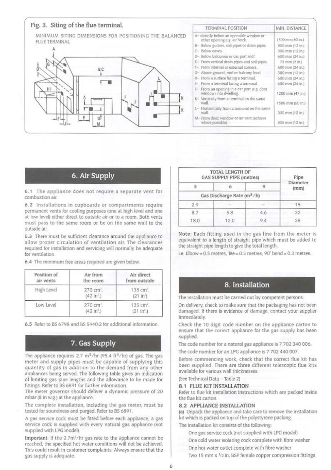
3. Siting of the
fl
ue
terminal.
I
~INIMUM
SITING
DIMENSIONS
FOR
POSITIONING
THE
BAlANCED
FlUE
TERMINAl
I
TERMINAl
POSITION
r
A•
dI!eelly
below
an
Openab!e
WlndO'.V
Or
othtt
opeoni"'i
t g
air
bnck.
a
Bt~oY.·
tLJUffl.
soil
pipes
or
dra:il'l
ptpes
c
..
Bciowe.r.n
MIN.
D
ISTAN
CE
1<.00mm(60.rt)
JOO
mm
1121tlJ
JOO
mm
112lll.J
600mmt24
tnJ
7Smm(311l.)
600
mm
(24
tn.J
300
mm
(121n.)
600mm(2.4
in)
600mm(2,d
in)
A
6.
Air
Supply
6.1 The appliance
does
not
require a
separate
vent
for
combustion
atr.
6.2
lns1allatlons
on
cupboards
or
compartments require
permanent vents
for
cooling purposes
(one
at high
level
and one
at
low
level)
either dtrect
to
outside air or
to
a
room.
Both
vents
must pass to the same room or be on the same wall
to
the
o
utside
air.
6.3
There must
be
sufficie
nt clearance around the appliance
to
allow proper circula
ti
on of
ventil~tlon
air. The cl
ea
ra
nces
required
for
Installation and servicing
will
normally beadequate
for
ventilation
6.4
The
mmlmum
free
areas required aregiven
below.
Position of
Air
from
Air
direct
air
vents the
room
from
outside
H1gh
Level
270cm'. t35 em'.
(42
in
'.)
121
ln'J
low
Level
270
cm
'. 135 em'.
(42
in
'.)
(21
in
'
.)
6.5
Refer
to
BS
6798 and
SS
5440:2
for
additional
Information.
7.
Gas
Supply
The appilance requires 2.7
m3
fh
r
(95.4
ft3fhr) of
gas.
The
gas
meter
and
supply pipes must be capable of supplyi
ng
this
quantity of gas in addition to
the
demand
from
a
ny
other
appliances
being
~rved.
T
he
fo
llowin
g table
gives
an
In
dica
tion
of
limiting
gas
pipe
lengths and the allowance
to
be made
for
fittings
Refer
10
BS
6891
fo
rfurther
in
for
mation
The meier governor should deliver a dynamic pressure of 20
mbar
(8
in
w.g.)at the appliance.
The complete tnstallallon. includtng
the
gas meter, must be
tested lorsoundnessand purged.
Refer
to
BS
6891
.
Agas servtce cock must be fitted
before
each apphance. a gas
service cock
Is
supplied with every natural gas appliance (not
supplied
w1th
LPG
model).
Important: If the 2
7m'/h
r gas
ra
te to
th
e app
li
ance
ca
n
no
t
be
reached.
th
e specified hot water condi
ti
ons
will
not beachieved.
This
could
resu
lt In customer complaints.
Always
ensu
re
that the
ga
s supply
IS
adequate.
6
o-
Wow
blkonlrs
or
c.lr
port
,oo{
E-
'-wrtr.oldr.wlpip<sandsol~
r-
from
lnlemal
or
external
comers
G-
Aboo.'t
around.
roof
0!
bakony
leo.'d
Jl
...
From
a
$Urface
facu-.g:a
termmill.
I
F'rom
~termina
l
facing
a
termmal
J
f'rom
M
opel'l
ing
tna
(ar
port
(e
.
.g.
door
window)
in
to
dwe-lling
K-
~rUclll
l
y
!rom
It
terminal
on
the
same
wall
L-
uonz.ontally
from
a:enninal
on
the
'l.~rnt
W.tll
M
From
door.
w~~Miow
or
a:r
\'ffit
1iC.h~
~-
..
po$$ibl<l
TOTAl
LENGTH
OF
GAS
SUPPLY
PIPE
(metres)
3 I 6 I 9
Gas Discharge Rate (ml/h)
2.9 -
..
8.7 5.8 4.6
18.0
12.0
9.4
1200m
m
(47i
n.
)
1SODmm(60in.)
300mm(12
in)
J00mm(12n)
Pipe
Diameter
(mm)
15
22
28
No
te
:
Eac
h filli
ng
used in the
gas
line from the meter is
equivalent
to
a
le
ngth of straight p
ip
e
which
must
be
added
to
th
estraight
pipe
le
ngth to
give
the towIlength.
i.e.
Elbow
• 0.5 metres,
Tee=O.S
metres. 90' bend=0.3 metres.
8. Installation
T
he
insta
ll
ation must becarri
ed
o
ut
by
competentpersons.
On
delivery,
check
to
make
su
re that the packaging has not
been
damaged
If
there
is
evidence
of
damage. contact your supplier
immediately
Check
the
10
dtgtt code number on
the
appliance carton to
ensure that the correct appliance
for
the gas supply has been
supplied
Thecode number
for
a naturalgasappliance
IS
7702 340
006.
The
code number
for
an
LPG
appliance
is
7702 440 007.
Before
commencing work. check that the correct
flue
kit
has
been supplied. There are three different telescopic flue kits
available forvarious
wall
thickne
sses.
(Sec
Thchn
l
ca
l
Data-
"lllbie
2)
8.1
FLUE
KITINST
AL
LA
TION
Refer
to
Oue
kit
in
stallation instructions
which
are packed inside
the nue
kit
carton.
8.2
APPLIANCE
INSTALLATION
(a)
Unpack
the applianceand takecare
to
remove
themstallation
kit
which
IS
packed
ontopofthe polystyrene
packmg.
The
installation
kit
consistsofthe
followmg
One
gas
serv1ce
cock
(not
supp
li
ed
wtth
LPG
model)
One
co
ld
water
iso
lating
cock
co
mplete
with
ftbre
washer
One
hot water outlet complete with
fibre
washer
1\No
15 mmx
'12
in.
SS
P
female
copper
com
press
ion
fittings


 Operation and maintenance instructions")